SINGLE ZONE MEGA WALL MOUNTED
ENGINEERING MANUAL
3/4, 1, 1-1/2, and 2 Tons
Mega Inverter Models:
LS090HEV1
LS120HEV1
LS180HEV1
LS240HEV1
3/4 and 1 Tons
Mega 115V Models:
LS090HXV
LS120HXV

For continual product development, LG Electronics U.S.A., Inc., reserves the right to change specifications without notice.
© LG Electronics U.S.A., Inc.
PROPRIETARY DATA NOTICE
This document, as well as all reports, illustrations, data, information,
and other materials are the property of LG Electronics U.S.A., Inc., and are
disclosed by LG Electronics U.S.A., Inc. only in confidence.
This document is for design purposes only.
A summary list of safety precautions is on page 4.
For more technical materials such as submittals, catalogs, installation,
owner’s, and service manuals, visit www.lghvac.com.
Due to our policy of continuous product innovation, some specications may change without notication.
©
LG Electronics U.S.A., Inc., Englewood Cliffs, NJ. All rights reserved. “LG ” is a registered trademark of LG Corp.
3
Introduction
About LG Electronics
LG Electronics is a global leader and technology innovator in
consumer electronics, mobile communications, and home
appliances. LG Electronics comprises five business units—Home
Entertainment, Mobile Communications, Air Conditioning, Business
Solutions, and Home Appliance. LG is one of the world’s leading
producers of flat panel televisions, audio and video products, mobile
handsets, air conditioners, and washing machines. LG’s commercial
air conditioning business unit was established in 1968 and has built
its lineup of residential and commercial products to include VRF,
Multi F, duct-free split systems, packaged terminal air conditioners
(PTACs), and room air conditioners. In 2011, the air conditioning and
energy solutions business unit grew to include LED lighting and solar
products. For more information, visit www.lg.com.
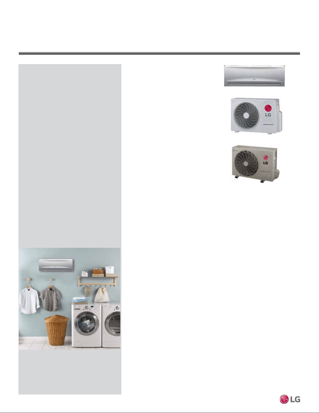
Duct-Free Split Systems
LG HVAC systems offer a range of solutions that are cost efficient,
quiet and attractive. Duct-Free Split systems are “split” into indoor
and outdoor units, and provide a smart alternative to both central
HVAC and window-mounted air conditioners. These inverter heat
pump systems are available in a variety of configurations to suit dif-
ferent cooling and heating situations. Installation by a qualified HVAC
contractor is safe and easy – little to no duct work or sheet metal is
required.
Inverter Systems
LG Single Zone Mega Inverter and Mega 115V Wall Mounted air-
source systems offer the opportunity to minimize ductwork in the
same configuration. The system offers zoning without the need for
zone damper systems. The LG Single Zone Mega Inverter Wall
Mount system’s advanced controls provide exceptional building
dehumidification and temperature control, and can rapidly adapt sys-
tem operating parameters to the ever changing building load. The LG
Single Zone Mega Inverter Wall Mounted system is easy to design,
install, and maintain. The modular design allows occupants to control
their environmental condition, providing individualized control of the
set-point temperature and allowing occupants to condition only the
occupied zones.
Quality Commitment
LG is committed to the success of Duct-Free Split projects. We
provide industry leading technical support during installation and
commissioning. LG offers a variety of classes designed for installers
and servicers to ensure that every system installation is completed
successfully.
Classes are conducted at LG’s training centers and in field locations
at various times throughout the year and upon special request.
Due to our policy of continuous product innovation, some specications may change without notication.
©
LG Electronics U.S.A., Inc., Englewood Cliffs, NJ. All rights reserved. “LG ” is a registered trademark of LG Corp.
4
Single Zone Mega Wall Mounted Engineering Manual
TABLE OF CONTENTS
INTRODUCTION ..................................................................................... 5
ARCHITECTURAL APPEAL .................................................................. 6
PRODUCT FEATURES AND BENEFITS ...............................................8
UNIT NOMENCLATURE ......................................................................... 9
General Data ................................................................................... 10-12
Electrical Data ...................................................................................... 13
Functions, Controls, and Options ...................................................... 14
Outdoor Unit Dimensions ................................................................... 15
LSU090HEV1, LSU120HEV1 ............................................................ 15
LSU180HEV1 .................................................................................... 16
LSU240HEV1 .................................................................................... 17
LSU090HXV1, LSU120HXV1 ............................................................ 18
Indoor Unit Dimensions ...................................................................... 19
LSN090HEV1 .................................................................................... 19
LSN120HEV1 .................................................................................... 20
LSN180HEV1, LSN240HEV1 ............................................................ 21
LSN090HXV, LSN120HXV ................................................................ 22
ACOUSTIC DATA .................................................................................23
Refrigerant Flow Diagrams ................................................................. 25
LSN/LSU90-180HEV1 ....................................................................... 25
LSN180HEV/LSU180HEV ................................................................. 26
LSN240HEV/LSU240HEV ................................................................. 27
LSN090HXV/LSU090HXV ................................................................. 28
Wiring Diagram .................................................................................... 29
LSN090HEV1 .................................................................................... 29
LSN120HEV1 .................................................................................... 30
LSN180HEV1, LSN240HEV1 ........................................................... 31
LSN090-120HXV ............................................................................... 32
LSU090HEV1, LSU120HEV1 ............................................................ 33
LSU180HEV1 ................................................................................... 34
LSU240HEV1 ................................................................................... 35
LSN090-120HXV ............................................................................... 36
Accessories ......................................................................................... 37
PERFORMANCE DATA ........................................................................ 39
Cooling Capacity ............................................................................... 40
Heating Capacity ............................................................................... 43
Equipment Selection Procedure ........................................................ 49
LS090~240HEV1 ............................................................................... 50
LS090HXV/LS120HXV ...................................................................... 51
Building Ventilation Design Guide ................................................ 52-53
Placement Considerations ............................................................ 54-56
REFRIGERANT PIPING DESIGN & LAYOUT
BEST PRACTICES ...............................................................................57
Refrigerant Piping Design .................................................................. 57
Design Guideline Summary ............................................................... 58
Selecting Field-Supplied Copper Tubing ........................................... 58
Installation & Layout Best Practices ................................................. 60
Refrigerant Piping System Layout ..................................................... 60
Piping Connection ............................................................................. 62
ELECTRICAL CONNECTIONS ............................................................64
Mechanical Specications .................................................................. 66
Acronyms ............................................................................................. 67
TABLE OF SYMBOLS
This symbol indicates an imminently hazardous situation which, if not avoided, will result in death or serious injury.
This symbol indicates a potentially hazardous situation which, if not avoided, could result in death or serious injury.
This symbol indicates a potentially hazardous situation which, if not avoided, may result in minor or moderate injury.
This symbol indicates situations that may result in equipment or property damage accidents only.
This symbol indicates an action should not be completed.
DANGER
CAUTION

INTRODUCTION
“Architectural Appeal” on page 6
6 | INTRODUCTION
Single Zone Mega Wall Mounted Engineering Manual
Due to our policy of continuous product innovation, some specications may change without notication.
©
LG Electronics U.S.A., Inc., Englewood Cliffs, NJ. All rights reserved. “LG ” is a registered trademark of LG Corp.
Benefits of Single Zone
Mega Inverter Wall Mounted
• Inverter technology
• Mega Inverter (HEV1) is available in 9,000,
12,000, 18,000, and 24,000 Btu/h capacities;
Mega 115V (HXV) is available in 9,000 and
12,000 Btu/h capacities
• All-season use - heat pump models for both
cooling and heating capabilities
• Operating ranges for Mega Inverter (HEV1)
and Mega 115V (HXV) outdoor units is 14°F to
118°F (DB) for cooling; 14°F to 65°F (WB) for
heating
• Operating range for all indoor units of 53°F to
75°F (WB) for cooling; 60°F to 86°F (DB) for
heating
• Quiet operation inside and outside
• Duct-free split system
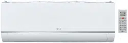
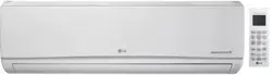
Convergence of Technological Innovation with Flexibility and Style
Single Zone Mega
Wall Mounted
Choosing an LG Single-Zone Mega Wall-
Mounted product provides a system de-
signer an edge to engineer a system with
individual control, and design flexibility
with advanced controls.
These single-zone systems are available
in a nominal capacity range of 3/4 to 2
tons. These are best suited for applica-
tions with zones that require heating or
cooling, such as residential, and small
business office buildings. Single-Zone
Mega Wall-Mounted outdoor and indoor
units are available in 208–230V/60Hz/1Ph
(HEV1) and 115V/60Hz/1Ph (HXV).
Adaptable and Flexible
Single-zone wall-mounted duct-free split
systems allow cooling or heating for the
entire residence or just a single room with-
out the need for invasive ductwork. There
is minimal renovation needed.
Long refrigerant piping lengths allow for
extra design flexibility in indoor unit instal-
lation.
These units may be used for a number of
residential or commercial environments
such as:
• Older homes
• New home construction
• Office buildings
• Restaurants
• Hospitals / Medical facilities
• Schools
• Nursing homes
• Retail establishments
• Houses of worship
Inverter Technology
Inverter variable-speed duct-free split
systems are measurably quieter and
consume less energy than conventional
air conditioners. The inverter compressor
ramps up or down to match the required
room capacity and maintain the comfort
level. When the selected temperature is
reached, the inverter compressor oper-
ates at low speed to maintain that comfort
level, thereby using less energy.
ARCHITECTURAL APPEAL

“Product Features and Benefits” on page 8
“Unit Nomenclature” on page 9
“General Data” on page 10
“Electrical Data” on page 13
“Outdoor Unit Dimensions” on page 15
“Indoor Unit Dimensions” on page 19
“Acoustic Data” on page 23
“Refrigerant Flow Diagrams” on page 25
“Wiring Diagrams—Indoor Units” on page 29
“Wiring Diagrams—Outdoor Units” on page 33
“Accessories - LG Monitoring View Diagnostic Software”
on page 37
PRODUCT DATA
8 | PRODUCT DATA
Single Zone Mega Wall Mounted Engineering Manual
Due to our policy of continuous product innovation, some specications may change without notication.
©
LG Electronics U.S.A., Inc., Englewood Cliffs, NJ. All rights reserved. “LG ” is a registered trademark of LG Corp.
Single Zone Mega Wall
Mounted
Single zone systems are equipped with
inverter components that offer superior
load matching and long piping installation.
These products work for optimizing power
consumption in residential and small office
buildings. Utilizing multiple indoor wall
mounted units each with custom tempera-
ture controls allow for precise temperature
settings in each zone of the building. Single
zone systems allow flexibility in interior
design and complement any decor.
Low Sound Levels
When outdoor units run at full load, they
have a quiet operating sound level. To pro-
mote a quiet, comfortable environment, the
LG single zone system indoor units operate
at sound levels as low as 23 dB(A) (HXV
units; 19dB(A) in Sleep mode) and outdoor
units as low as 47 dB(A) at full load. All
rotating components are soft-started by the
controller using digitally controlled inverters,
which reduce undesirable noise caused by
fans and compressors cycling on and off.
Comfort Control at Its
Best
Unlike traditional air conditioning control
systems, which use thermostatic controls to
maintain room temperatures, LG single zone
inverter controls continuously vary the indoor
unit fan speed and refrigerant flow.
LG single zone one-to-one systems continu-
ously measure the room temperatures and
adjust system operations accordingly to
maintain set temperature.
The outdoor unit responds by varying the
compressor speed and outdoor fan motors
as needed to maintain system operating
pressure. As a result, single zone systems
deliver precise space temperature control.
Inverter Driven
The single rotary (9k/12k Btu/h systems)
and twin-rotary (18k/24k Btu/h systems)
compressor is optimized to maximize
compressor efficiency, which reduces power
consumption and monthly utility bills. This
latest inverter technology allows single zone
system outdoor units to vary the compressor
motor shaft speed to deliver an appropriate
amount of cooling to the indoor unit. Precise
refrigerant volume delivery translates into
long periods with coil surface temperatures
below dew point and minimizes compressor
and fan component run time, which may lead
to lower utility usage.
Simplified Installation
Cooling and heating applications that use
single zone systems simplify and reduce the
mechanical and control system design time.
The designer no longer has to be concerned
with interconnecting chilled and condenser
water piping, air-distribution duct systems,
matching and selecting chillers, towers,
pumps, coils, fans, air handlers, or Variable
Air Volume (VAV) boxes.
Operating Range
Single zone systems have a nominal capac-
ity range of 3/4 to 2 tons (depending on
outdoor/indoor units).
Outdoor unit operating ranges for both Mega
Inverter (HEV1) and Mega 115V (HXV)
single zone systems:
Cooling: 14°F DB to 118°F DB
Heating: 14°F WB to 65°F WB
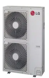
Compact Size
Single zone outdoor units have the following
footprints.
LSU090HEV1, LSU120HEV1
(WxHxD (in.)): 28-1/4 x 19-1/2 x 9-1/16
LSU180HEV1
(WxHxD (in.)): 30-5/16 x 21-1/2 x 11-5/16
LSU240HEV1
(WxHxD (in.)): 34-1/4 x 25-13/16 x 12-19/32
LSU090HXV, LSU120HXV
(WxHxD (in.)): 28-1/4 x 19-1/32 x 9-1/16
Fin Design with Gold-
Fin™ Coating
All single zone outdoor units are provided
with large surface coils made of copper
tubes with louvered aluminum fins designed
to maximize unit operating efficiency over a
wide range of ambient conditions.
Standard from the factory, every single zone
outdoor unit coil fin surface is coated with
LG’s exclusive GoldFin™ anti-corrosive
coating designed to prevent natural surface
corrosion of the aluminum fins. This main-
tains heat transfer properties of the coil for
an extended time.
A hydrophilic coating is applied to the
outdoor unit coil fin surface over the GoldFin
coating. This coating enhances the develop-
ment of heavier water droplets gathering on
the fin surface. As a result, the droplets roll
off the fin surfaces, delaying the point when
frost forms on the coil surface during heat-
ing operation. This coating also makes it
possible to easily clean the outdoor unit coil
using a mild soap.
Other Features
• Inverter variable speed compressor
• Jet Cool/Jet Heat
• Dehumidifying mode
• Chaos Wind
• Auto restart
• Auto operation
• Self-cleaning indoor coil
• Condensate sensor connection
• Smaller footprint
• Precision load matching
• Meets AHRI 210/240
PRODUCT FEATURES AND BENEFITS
PRODUCT DATA | 9
Product Data
Due to our policy of continuous product innovation, some specications may change without notication.
©
LG Electronics U.S.A., Inc., Englewood Cliffs, NJ. All rights reserved. “LG ” is a registered trademark of LG Corp.
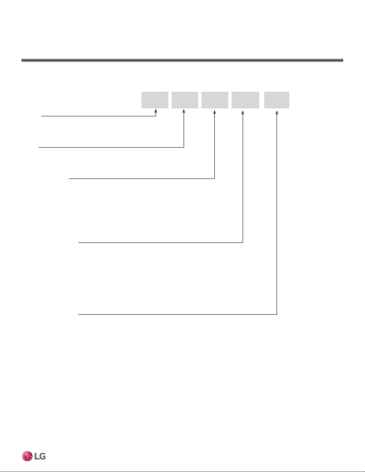
UNIT NOMENCLATURE
Single Zone Wall Mount Indoor and Outdoor Units
LS
N 090 HEV 1
Type
N = Indoor Wall Mount Unit
U = Outdoor Heat Pump Unit
Family
LA= Art Cool Premier / Gallery / Mirror
LS= High Efficiency Wall Mount / Standard / Mega
Generation or Revision
1 = First
2 = Second
3 = Third
4 = Fourth
Nominal Capacity
(Nominal cooling capacity in Btu/h)
090/091 = 9,000
120/121 = 12,000
180/181 = 18,000
240 = 24,000
300/307 = 30,000
360 = 36,000
Indoor/Outdoor Product
HEV = Mega
HXV = Mega 115V
HYV = Art Cool Premier
HVP = Art Cool Gallery
HSV = Art Cool Mirror, High Efficiency
HV = Standard
HLV = Extended Pipe
10 | PRODUCT DATA
Single Zone Mega Wall Mounted Engineering Manual
Due to our policy of continuous product innovation, some specications may change without notication.
©
LG Electronics U.S.A., Inc., Englewood Cliffs, NJ. All rights reserved. “LG ” is a registered trademark of LG Corp.
GENERAL DATA
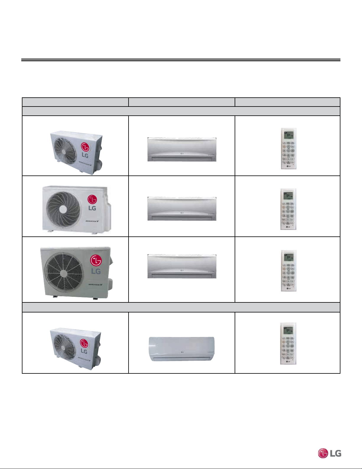
Mega Pairing Table
Outdoor Unit Model Indoor Unit Model Controller
Mega Inverter
LSU090HEV1
LSU120HEV1
LSN090HEV1
LSN120HEV1
AKB73835318
LSU180HEV1 LSN180HEV1 AKB73835318
LSU240HEV1 LSN240HEV1 AKB73835318
Mega 115V
LSU090HXV
LSU120HXV
LSN090HXV
LSN120HXV
AKB73456121
Table 1: Single Zone Mega Inverter and Mega 115V Pairing Table
The following table shows the available outdoor and indoor unit, along with the factory provided controller.

PRODUCT DATA | 11
Product Data
Due to our policy of continuous product innovation, some specications may change without notication.
©
LG Electronics U.S.A., Inc., Englewood Cliffs, NJ. All rights reserved. “LG ” is a registered trademark of LG Corp.
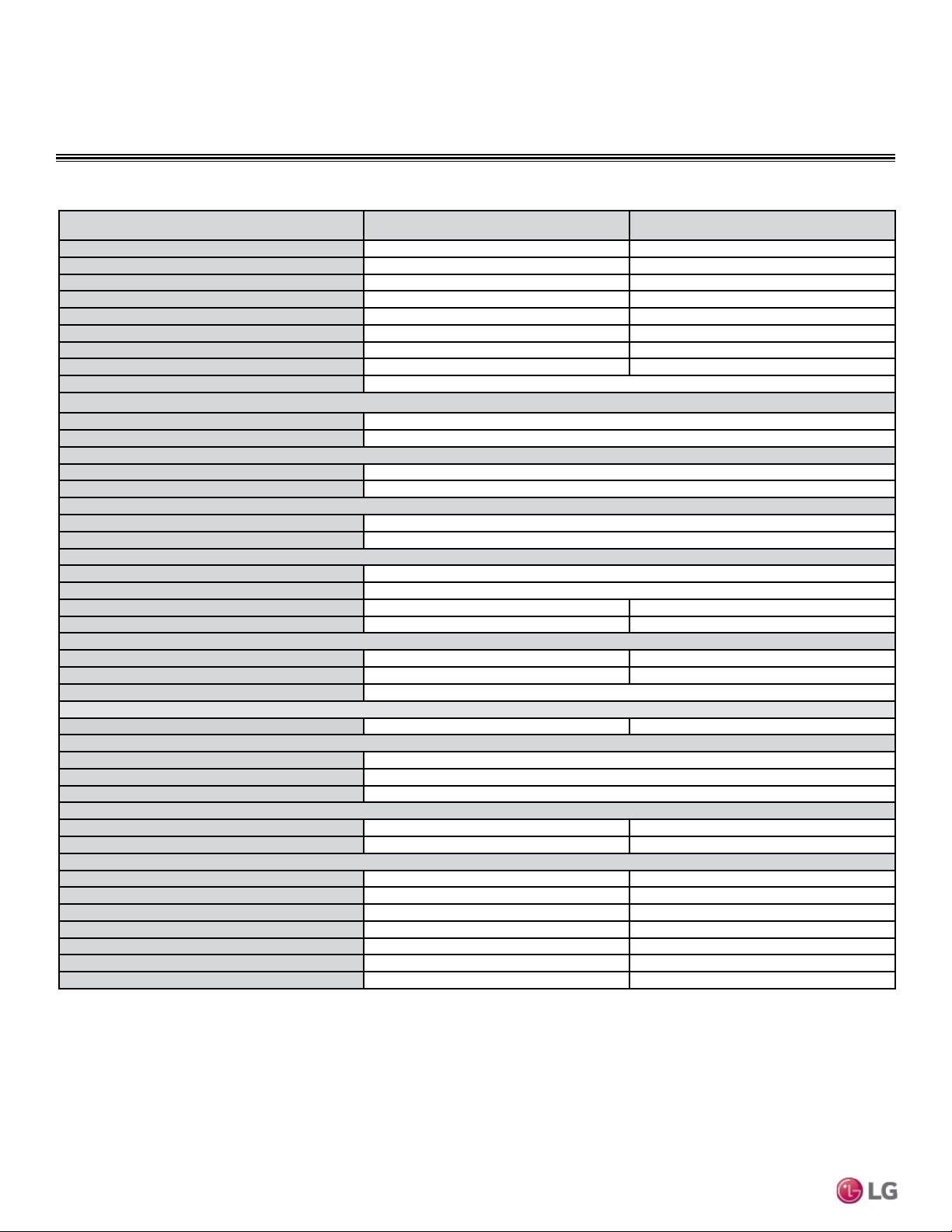
Table 2: Single Zone Mega Inverter System Specications.
GENERAL DATA
Mega Inverter Specications
System Model Number (IDU/ODU)
LS090HEV1
(LSN090HEV1/
LSU090HEV1)
LS120HEV1
(LSN120HEV1/
LSU120HEV1)
LS180HEV1
(LSN180HEV1/
LSU180HEV1)
LS240HEV1
(LSN240HEV1/
LSU240HEV1)
Cooling Capacity (Min/Rated/Max) (Btu/h)
3,070 ~ 8,500 ~ 9,500 3,070 ~ 12,000 ~ 13,780 3,685 ~ 17,000 ~ 18,493 3,685 ~ 22,000 ~ 24,000
Cooling Power Input
1
(kW)
0.68 1.14 1.55 2.045
Heating Capacity (Min/Rated/Max) (Btu/h)
3,070 ~ 9,000 ~ 10,500 3,070 ~ 12,000 ~ 13,780 3,685 ~ 19,000 ~ 22,997 3,685 ~ 22,000 ~ 24,226
Heating Power Input
1
(kW)
0.78 0.98 1.59 1.935
COP
11.54 12.24 11.95 11.37
Max. Heating Capacity (Btu/h)
Outdoor 17°F (WB)/Indoor 70°F (DB)
5,570 (62%) 7,620 (63%) 15,580 (82%) 18,040 (82%)
EER
12.5 10.52 10.97 10.76
SEER
19.0 17.0 18.0 17.0
HSPF
9.0 9.2 9.0 9.0
Power Supply (V/Hz/Ø)
208-230/60/1
Outdoor Unit Operating Range
Cooling (°F DB)
14 to 118
Heating (°F WB)
14 to 65
Indoor Unit Operating Range
Cooling (°F WB)
53 to 75
Heating (°F DB)
60 to 86
Indoor Temperature Setting Range
Cooling (°F)
64 to 86
Heating (°F)
60 to 86
Unit Data
Refrigerant Type
2
R410A
Refrigerant Control
EEV
IDU Sound Pressure
3
dB(A) (H/M/L/Sleep)
39/33/25/19 39/33/25/19 42/40/35/29 45/40/35/29
ODU Sound Pressure
3
dB(A)
47 47 51 53
Unit Weight (lbs)
IDU (Net/Shipping)
17/20 23/28 28/30 28/32
ODU (Net/Shipping)
62/67 62/67 78/82 95/104
Power/Communication Cable
4
(No. x AWG)
4 x 18
Compressor
Compressor Type (Qty)
Single Rotary (1) Single Rotary (1) Twin Rotary (1) Twin Rotary (1)
Fan
IDU Type (Qty)
Cross Flow (1)
ODU Type (Qty)
Propeller (1)
Motor/Drive
Brushless Digital Controlled/Direct
Airflow Rate
IDU Max/H/M/L (CFM)
318/276/226/177 424/353/272/212 629/512/441/353 689/600/494/388
ODU Max (CFM)
953 953 1,342 1,766
Piping
Liquid Line (in, OD)
1/4 1/4 1/4 1/4
Vapor Line (in, OD)
3/8 3/8 1/2 5/8
Condensation Line (OD, ID)
27/32, 5/8 27/32, 5/8 27/32, 5/8 27/32, 5/8
Additional Refrigerant Charge (oz/ft)
0.22 0.22 0.33 0.33
Pipe Length
5
(Minimum/Maximum)(ft)
9.8/49.2 9.8/49.2 9.8/65.6 9.8/65.6
Piping Length
5
(no add’l refrigerant, ft)
24.6 24.6 24.6 24.6
Max Elevation Difference (ft)
22.9 22.9 32.8 32.8
EEV: Electronic Expansion Valve IDU: Indoor Unit ODU: Outdoor Unit
1
Power Input is rated at high speed.
2
Take appropriate actions at the end of HVAC equipment life to recover, recycle, reclaim or destroy
R410A refrigerant according to applicable regulations (40 CFR Part 82, Subpart F) under section 608
of CAA.
3
Sound Pressure levels are tested in an anechoic chamber under ISO Standard 3745.
4
All power wiring/communication cables are field supplied and are to be minimum 18 AWG, 4-conductor,
stranded, shielded and must comply with applicable local and national codes.
5
Piping lengths are equivalent.
This unit comes with a dry helium charge.
This data is rated 0 ft above sea level with 24.6 of refrigerant line per indoor unit and a 0 ft level
difference outdoor and indoor units.
Cooling capacity rating obtained with air entering the indoor unit at 80ºF dry bulb (DB) and 67ºF wet
bulb (WB) and outdoor ambient conditions of 95ºF dry bulb (DB) and 75ºF wet bulb (WB).
Heating capacity rating obtained with air entering the indoor unit at 70ºF dry bulb (DB) and 59ºF wet
bulb (WB) and outdoor ambient conditions of 47ºF dry bulb (DB) and 43ºF wet bulb (WB).
12 | PRODUCT DATA
Single Zone Mega Wall Mounted Engineering Manual
Due to our policy of continuous product innovation, some specications may change without notication.
©
LG Electronics U.S.A., Inc., Englewood Cliffs, NJ. All rights reserved. “LG ” is a registered trademark of LG Corp.
GENERAL DATA
Mega 115V Specications
Table 3: Single Zone Mega 115V System Specications.
System Model Number (IDU/ODU) LS090HXV (LSN090HXV/LSU090HXV) LS120HXV (LSN120HXV/LSU120HXV)
Cooling Capacity (Min/Rated/Max) (Btu/h)
1,023 ~ 8,500 ~ 13,785 1,023 ~ 12,000 ~ 13,785
Cooling Power Input
1
(kW)
0.71 1.14
Heating Capacity (Min/Rated/Max) (Btu/h)
1,023 ~ 10,900 ~ 22,178 1,023 ~ 13,000 ~ 22,178
Heating Power Input
1
(kW)
0.88 1.09
COP
3.63 3.50
EER
12.01 10.5
SEER
17.0 17.0
HSPF
9.0 9.0
Power Supply (V/Hz/Ø)
115/60/1
Outdoor Unit Operating Range
Cooling (°F DB)
14 to 118
Heating (°F WB)
14 to 65
Indoor Unit Operating Range
Cooling (°F WB)
53 to 75
Heating (°F DB)
60 to 86
Indoor Temperature Setting Range
Cooling (°F)
65 to 86
Heating (°F)
60 to 86
Unit Data
Refrigerant Type
2
R410A
Refrigerant Control
EEV
IDU Sound Pressure
3
dB(A) (H/M/L/Sleep)
39/33/23/19 39/33/23/19
ODU Sound Pressure
3
dB(A)
47 47
Unit Weight (lbs)
IDU (Net/Shipping)
23/26 23/26
ODU (Net/Shipping)
67/79 67/79
Power/Communication Cable
4
(No. x AWG)
4 x 18
Compressor
Compressor Type (Qty)
Single Rotary (1) Single Rotary (1)
Fan
IDU Type (Qty)
Cross Flow (1)
ODU Type (Qty)
Propeller (1)
Motor/Drive
Brushless Digitally Controlled/Direct
Airflow Rate
IDU Max/H/M/L (CFM)
335/272/212/124 335/272/212/124
ODU Max (CFM)
1,000 1,000
Piping
Liquid Line (in, OD)
1/4 1/4
Vapor Line (in, OD)
3/8 3/8
Condensation Line (OD, ID)
27/32, 5/8 27/32, 5/8
Additional Refrigerant Charge (oz/ft)
0.22 0.22
Pipe Length
5
(Minimum/Maximum)(ft)
6.6 / 49.2 6.6 / 49.2
Piping Length
5
(no add’l refrigerant, ft)
24.6 24.6
Max Elevation Difference (ft)
23 23
EEV: Electronic Expansion Valve IDU: Indoor Unit ODU: Outdoor Unit
1
Power Input is rated at high speed.
2
Take appropriate actions at the end of HVAC equipment life to recover, recycle, reclaim or destroy
R410A refrigerant according to applicable regulations (40 CFR Part 82, Subpart F) under section 608
of CAA.
3
Sound Pressure levels are tested in an anechoic chamber under ISO Standard 3745.
4
All power wiring/communication cables are field supplied and are to be minimum 18 AWG, 4-conductor,
stranded, shielded and must comply with applicable local and national codes.
5
Piping lengths are equivalent.
This unit comes with a dry helium charge.
This data is rated 0 ft above sea level with 24.6 of refrigerant line per indoor unit and a 0 ft level
difference outdoor and indoor units.
Cooling capacity rating obtained with air entering the indoor unit at 80ºF dry bulb (DB) and 67ºF wet
bulb (WB) and outdoor ambient conditions of 95ºF dry bulb (DB) and 75ºF wet bulb (WB).
Heating capacity rating obtained with air entering the indoor unit at 70ºF dry bulb (DB) and 59ºF wet
bulb (WB) and outdoor ambient conditions of 47ºF dry bulb (DB) and 43ºF wet bulb (WB).
PRODUCT DATA | 13
Product Data
Due to our policy of continuous product innovation, some specications may change without notication.
©
LG Electronics U.S.A., Inc., Englewood Cliffs, NJ. All rights reserved. “LG ” is a registered trademark of LG Corp.
Model Number Nominal Tons
Compressor
Qty
Compressor(A)
Cool/Heat
Fan Qty ODU Fan (A) IDU Fan (A) MCA(A) MOP(A)
LS090HEV1 3/4 1 7.0/7.0 1 0.5 0.5 10 15
LS120HEV1 1 1 7.0/7.0 1 0.5 0.5 10 15
LS180HEV1 1-1/2 1 8.81/8.61 1 0.4 0.4 12 20
LS240HEV1 2 1 10.72/10.28 1 0.4 0.4 15 20
Mega Inverter and Mega 115V Outdoor Units
ELECTRICAL DATA
Table 4: 208-230V, 60Hz, 1-Phase Single-Zone Mega Inverter System Electrical Data Table.
Table 5: 115V, 60Hz, 1-Phase Single Zone Single-Zone Mega 115V System Electrical Data Table.
Model Number Nominal Tons
Compressor
Qty
Compressor(A)
Cool/Heat
Fan Qty ODU Fan(A) IDU Fan (A) MCA(A) MOP(A)
LS090HXV 3/4 1 10/10 1 0.4 0.5 13.5 20
LS120HXV 1 1 10/10 1 0.4 0.5 13.5 20
Voltage tolerance is ±10%.
Maximum allowable voltage unbalance is 2%.
MCA = Minimum Circuit Ampacity.
Maximum Overcurrent Protection (MOP) is calculated as follows: (Largest motor FLA x 2.25) + (Sum of
other motor FLA) rounded down to the nearest standard fuse size.
Voltage tolerance is ±10%.
Maximum allowable voltage unbalance is 2%.
MCA = Minimum Circuit Ampacity.
Maximum Overcurrent Protection (MOP) is calculated as follows: (Largest motor FLA x 2.25) + (Sum of
other motor FLA) rounded down to the nearest standard fuse size.
14 | PRODUCT DATA
Single Zone Mega Wall Mounted Engineering Manual
Due to our policy of continuous product innovation, some specications may change without notication.
©
LG Electronics U.S.A., Inc., Englewood Cliffs, NJ. All rights reserved. “LG ” is a registered trademark of LG Corp.
FUNCTIONS, CONTROLS, OPTIONS
Table 6: Indoor Units—Functions, Controls and Options.
Indoor Unit Type LS090-120-180-240HEV1 LS090-120HXV
Airow
Air supply outlet
1 1
Airflow direction (left/right)
Manual Auto
Airflow direction (up/down)
Auto Auto
Auto swing (left/right)
X √
Auto swing (up/down)
√ √
Airflow steps (fan/cool/heat)
4 / 4 / 4 6 / 6 / 6
Auto swing
√ √
Auto wind
√ √
Jet-cool/heat
√ / √ √ / √
Swirl wind
X X
One touch soft air
√ X
Air Purifying
Washable anti-fungal
1
√ √
Deodorizing filter
X X
Plasma
2
X X
Allergy free filter
X X
3M Micro Protection filter
2
X X
Functions
Drain pump
X X
E.S.P. control
X X
Electric heater
X X
High ceiling
X X
Defrost
√ √
Low ambient
√ √
Hot start
√ √
Self diagnostics
√ √
Soft dry (dehumidification)
√ √
Auto changeover
√ √
Auto clean (coil dry)
√ √
Auto restart
√ √
Child lock
X X
Forced operation
√ √
Sleep mode
√ √
Timer (24hr on/off)
√ √
Weekly timer
X X
Two thermistor control
X X
Controllers
Wireless Remote Controller
√ √
Simple Controller with Mode Selection
X o
Simple Controller without Mode Selection
X o
LG Programmable Thermostat
X o
Dry contact
X o
Central control (LGAP)
X X
PI 485
X X
Special Function Kit
Zone control
X X
CTIE
X X
Electro thermostat
X X
Wi-Fi Module (Option)
X X
Water level sensor connection (for optional AG-9300-LG)
o o
Wind baffle kit
X X
Other
Thermistor
X X
1
Primary washable filters.
2
Secondary filters.
√ = Standard feature
o = Optional accessory (must be purchased separately)
X = Not available
PRODUCT DATA | 15
Product Data
Due to our policy of continuous product innovation, some specications may change without notication.
©
LG Electronics U.S.A., Inc., Englewood Cliffs, NJ. All rights reserved. “LG ” is a registered trademark of LG Corp.
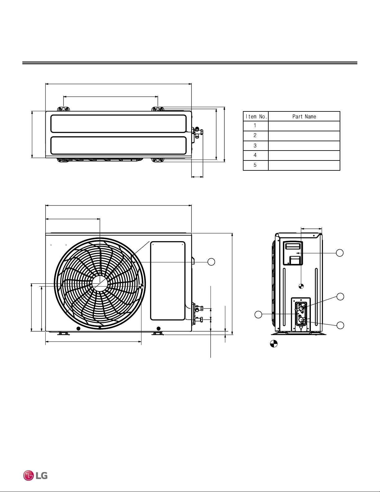
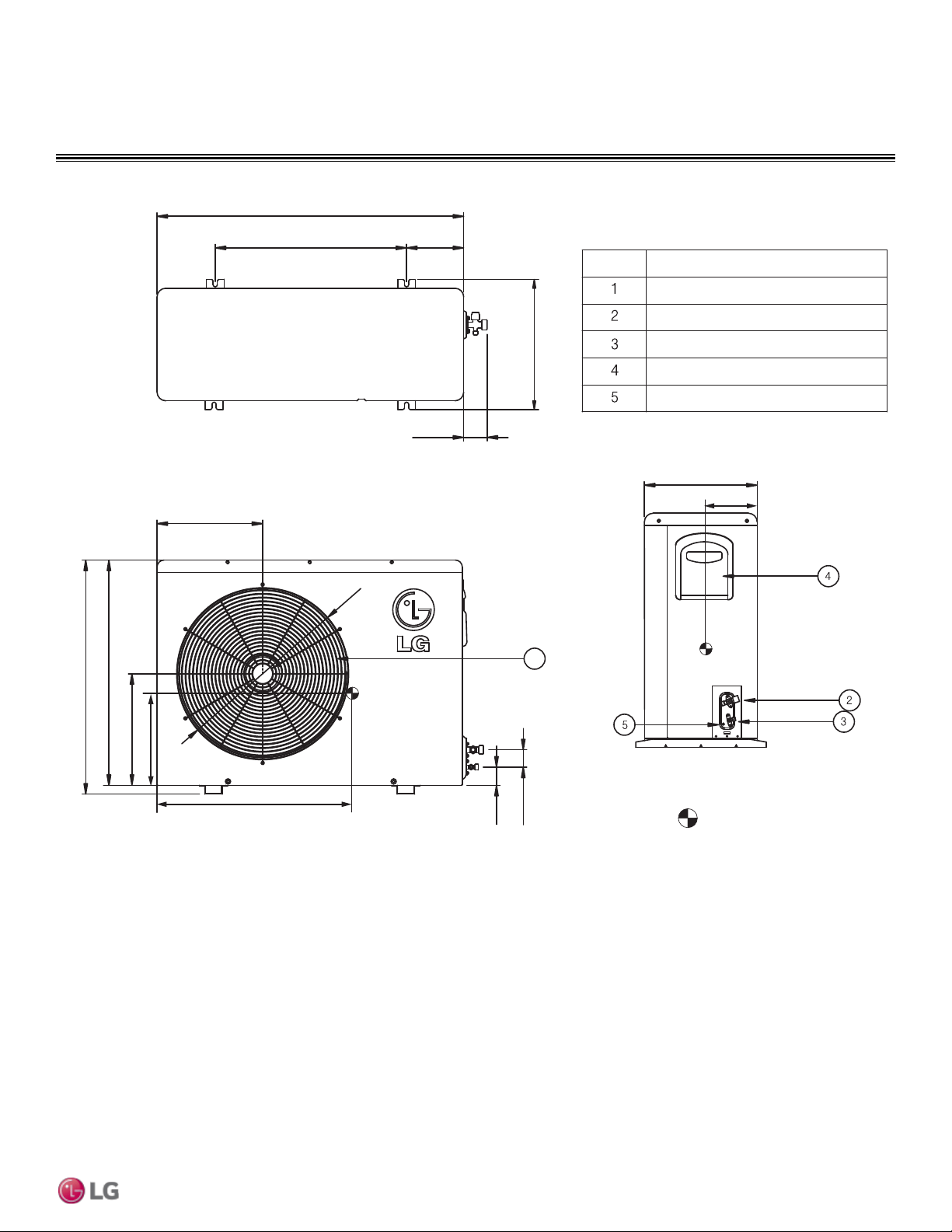
OUTDOOR UNIT DIMENSIONS
LSU090HEV1, LSU120HEV1
5
4
2
3
18-1/4
28-1/4
28-1/4
Ø17-3/8
2-1/4
4-5/8
10-9/16
18-3/4
9-5/16
8-5/8
19-1/2
2-3/16
2-1/4
1/2
10-1/16
9-1/16
10-11/16
1
Center of gravity
Unit: Inch
Discharge Air Grille
Gas Pipe Connection Port
Liquid Pipe Connection Port
Control Box
Ground Terminal
16 | PRODUCT DATA
Single Zone Mega Wall Mounted Engineering Manual
Due to our policy of continuous product innovation, some specications may change without notication.
©
LG Electronics U.S.A., Inc., Englewood Cliffs, NJ. All rights reserved. “LG ” is a registered trademark of LG Corp.
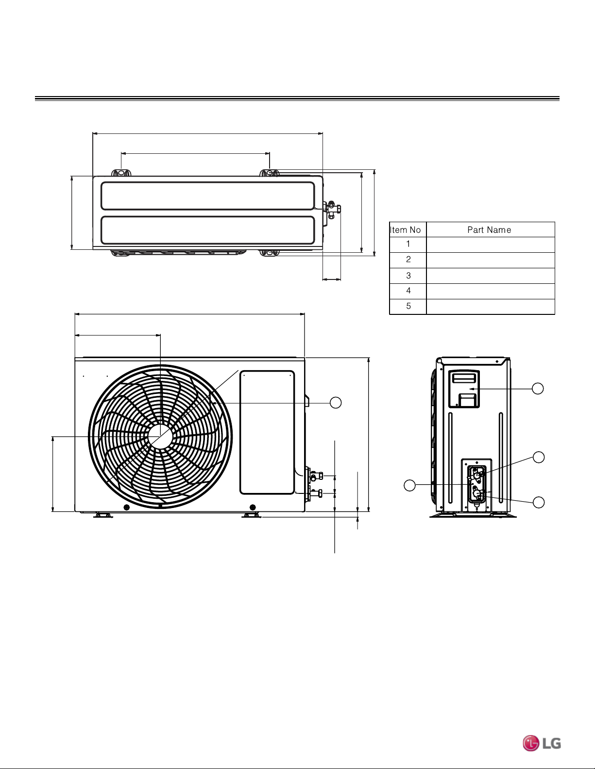
LSU180HEV1
OUTDOOR UNIT DIMENSIONS
30-5/16
22
4-3/16
13-15/16
6-1/8
2-1/8
10-15/16
1
20-15/16
21-1/2
10-1/2
8 -1/8
4
3
2
5
11-5/16
Item No. Part Name
2-13/16
Ø
18-5/16
Unit: Inch
Center of Gravity
9-3/8
20
5-3/4
Discharge Air Grille
Gas Pipe Connection Port
Liquid Pipe Connection Port
Control Box
Ground Terminal
PRODUCT DATA | 17
Product Data
Due to our policy of continuous product innovation, some specications may change without notication.
©
LG Electronics U.S.A., Inc., Englewood Cliffs, NJ. All rights reserved. “LG ” is a registered trademark of LG Corp.
OUTDOOR UNIT DIMENSIONS
LSU240HEV1
1
34-1/4
21-1/2 6-5/16
14 -3/16
2-3/16
11-15/16
Ø
20-15/16
25-13/16
24-13/16
12-5/8
3
3-1/8
12-5/8
Item No.
Part Name
Unit: Inch
Center of Gravity
10-7/16
21-1/8
5-13/16
Discharge Air Grille
Gas Pipe Connection Port
Liquid Pipe Connection Port
Control Box
Ground Terminal
18 | PRODUCT DATA
Single Zone Mega Wall Mounted Engineering Manual
Due to our policy of continuous product innovation, some specications may change without notication.
©
LG Electronics U.S.A., Inc., Englewood Cliffs, NJ. All rights reserved. “LG ” is a registered trademark of LG Corp.
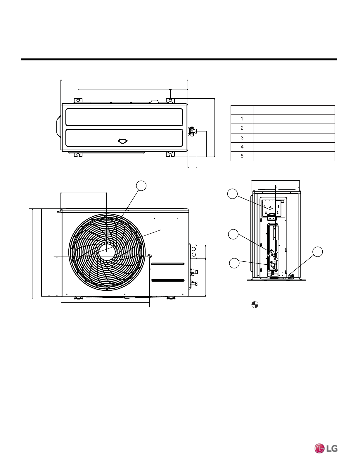
OUTDOOR UNIT DIMENSIONS
LSU090HXV, LSU120HXV
5
4
2
3
28-1/4
Ø17-3/8
10-9/16
9-5/16
19-1/16
2-3/16
2-1/4
7/16
1
Unit: Inch
.
18-1/4
28-1/4
2-1/4
10 -1/16
9-1/16
10-11/16
Discharge Air Grille
Gas Pipe Connection Port
Liquid Pipe Connection Port
Control Box
Ground Terminal
PRODUCT DATA | 19
Product Data
Due to our policy of continuous product innovation, some specications may change without notication.
©
LG Electronics U.S.A., Inc., Englewood Cliffs, NJ. All rights reserved. “LG ” is a registered trademark of LG Corp.
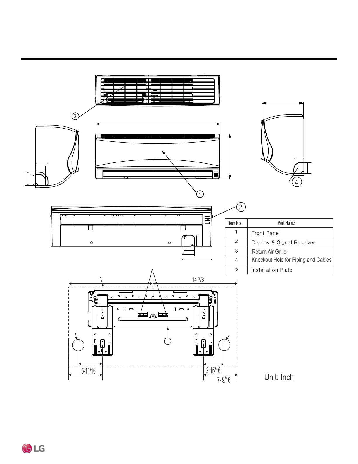
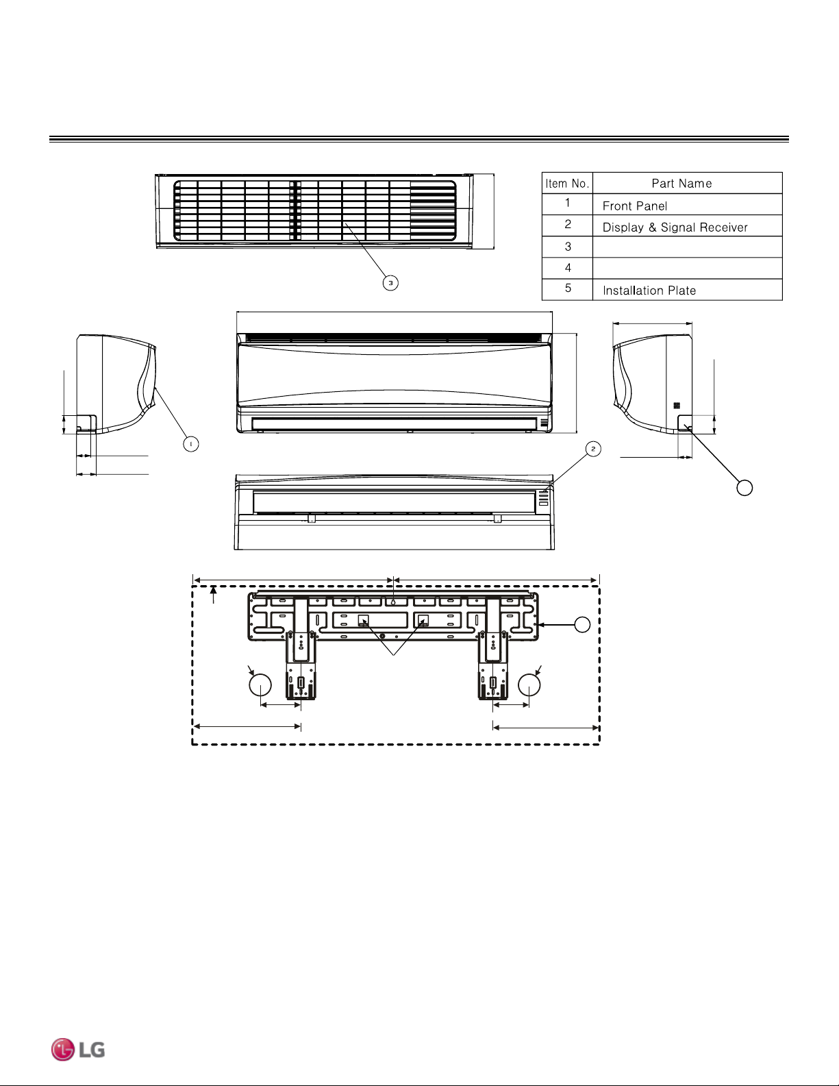
INDOOR UNIT DIMENSIONS
LSN090HEV1
Ø
2-9/16
Ø
2-9/16
Right rear piping
Left rear piping
Installation Plate
Place a level on raised tab
Unit Outline
7- 9/16
14-7/8
29-3/4
7-1/4
10 -7/16
5
3
4
1
2
Unit: Inch
14-7/8
7- 9/16
Item No.
Part Name
2-15/16
5-11/16
Return Air Grille
Knockout Hole for Piping and Cables
1-3/4
2-3/16
2
2-3/8
5-5/8
2
2-1/8
2-3/8
2
1-3/4
20 | PRODUCT DATA
Single Zone Mega Wall Mounted Engineering Manual
Due to our policy of continuous product innovation, some specications may change without notication.
©
LG Electronics U.S.A., Inc., Englewood Cliffs, NJ. All rights reserved. “LG ” is a registered trademark of LG Corp.
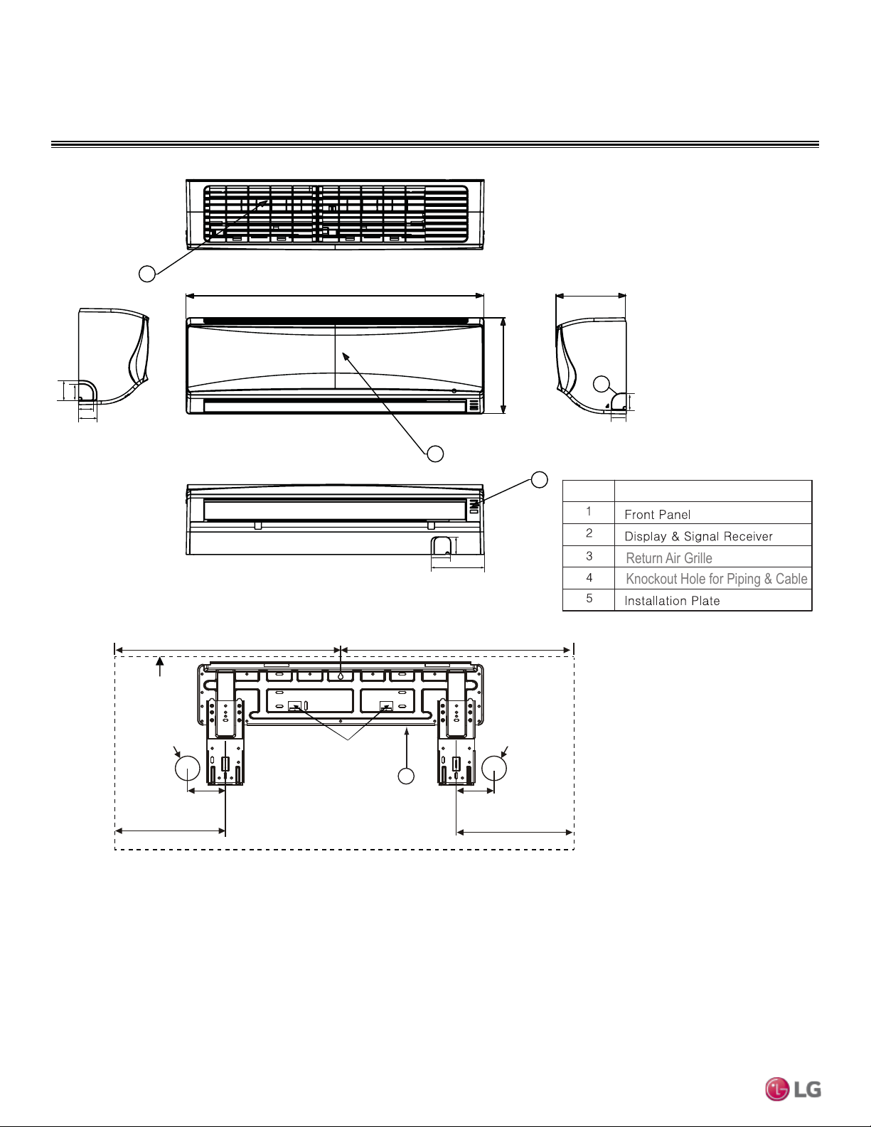
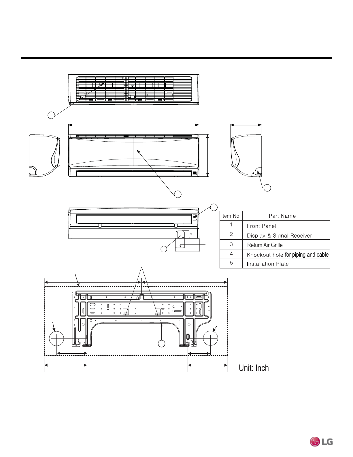
INDOOR UNIT DIMENSIONS
LSN120HEV1
5
Ø
2-9/16
Right Rear
Piping
Left Rear
Piping
Installation Plate
Place a level on raised tab
4 -13/16
9-5/8
7
5-1/4
16 -1/4
18-7/8
34-13/16
8-1/4
11 -1/4
Unit Outline
Ø
2-9/16
3
2
4
1
Unit: Inch
Item No.
Part Name
Return Air Grille
1-3/4
2-3/16
2
2-3/8
1-3/4
2
Knockout Hole for Piping & Cable
2
2-5/16
6-5/16
PRODUCT DATA | 21
Product Data
Due to our policy of continuous product innovation, some specications may change without notication.
©
LG Electronics U.S.A., Inc., Englewood Cliffs, NJ. All rights reserved. “LG ” is a registered trademark of LG Corp.
INDOOR UNIT DIMENSIONS
LSN180HEV1, LSN240HEV1
Unit
Outline
Left Rear
Piping
Right Rear
Piping
Place a level on raised tab
Ø2-9/16
Ø2-9/16
18-1/8 22-3/8
8-11/16
12-1/8
7.24in(184mm)
7-1/4
6.14in(156mm)
6-3/16
9-13/16
2-9/16
1-13/16
2-1/16
40-9/16
12-13/16
9-13/16
5
4
2-1/16
1-13/16
Unit: Inch
R
eturn Air
G
rille
K
nockout Hole for Piping & Cable
22 | PRODUCT DATA
Single Zone Mega Wall Mounted Engineering Manual
Due to our policy of continuous product innovation, some specications may change without notication.
©
LG Electronics U.S.A., Inc., Englewood Cliffs, NJ. All rights reserved. “LG ” is a registered trademark of LG Corp.
INDOOR UNIT DIMENSIONS
LSN090HXV, LSN120HXV
34-7/8
8-5/16
11 -1/4
3
2
4
1
Ø
2-13/16
5-1/4
3-3/4
Right rear
piping
Left rear
piping
Installation Plate
Place a level on raised tab
Unit Outline
8-9/16
6-15/16
17-7/16 17-7/16
5
Ø
2-13/16
4
2-5/16
6-5/16
15/16
Unit: Inch
Return Air Grille
for piping and cable
PRODUCT DATA | 23
Product Data
Due to our policy of continuous product innovation, some specications may change without notication.
©
LG Electronics U.S.A., Inc., Englewood Cliffs, NJ. All rights reserved. “LG ” is a registered trademark of LG Corp.
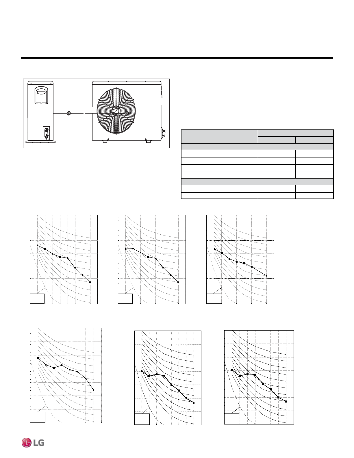
Mega Inverter and Mega 115V Outdoor Units
Model
Sound Pressure Levels (dB[A])
Cooling (Max) Heating (Max.)
Mega Inverter
LSU090HEV1 47 47
LSU120HEV1 47 47
LSU180HEV1 51 51
LSU240HEV1 53 53
Mega 115V
LSU090HXV 47 47
LSU120HXV 47 47
Table 7: Outdoor Unit Acoustic Data
Figure 1: Outdoor Unit Sound Levels
3.28 ft
Center of
Outdoor Unit
Figure 2: Sound Pressure Levels for Mega Inverter Outdoor Units.
• Measurements are taken 3.28 ft away from the front of the unit.
• Sound pressure levels are measured in dB(A) with a tolerance of ±3.
• Sound pressure levels are tested in an anechoic chamber under
ISO Standard 3745.
• Sound level will vary depending on a range of factors including the
construction (acoustic absorption coefficient) of a particular room in
which the unit was installed.
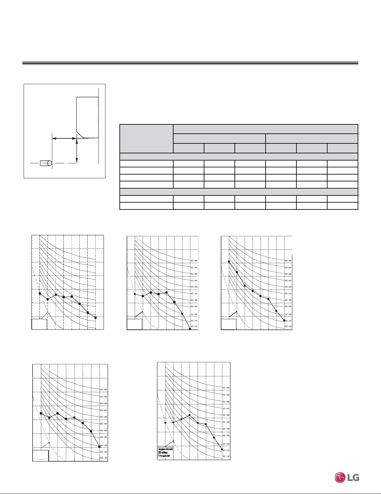
OUTDOOR UNIT ACOUSTIC DATA
Figure 3: Sound Pressure Levels for Mega 115V Outdoor Units.
Octave Band Center Frequency (Hz)
Octave Band Sound Pressure Level (0dB = 20μPa)
10
20
30
40
50
60
70
80
63 125 250 500 1000 2000 4000 8000
NC-15
NC-20
NC-25
NC-30
NC-35
NC-40
NC-45
NC-50
NC-55
NC-60
NC-65
Approximate
Hearing
Threshold
LSU090HXV
10
20
30
40
50
60
70
80
63 125 250 500 1000 2000 4000 8000
NC-15
NC-20
NC-25
NC-30
NC-35
NC-40
NC-45
NC-50
NC-55
NC-60
NC-65
Approximate
Hearing
Threshold
Octave Band Sound Pressure Level (0dB = 20μPa)
Octave Band Center Frequency (Hz)
LSU120HXV
10
20
30
40
50
60
70
80
63 125 250 500 1000 2000 4000 8000
Octave Band Sound Pressure Level (0dB = 20μPa)
Octave Band Center Frequency (Hz)
NC-15
NC-20
NC-25
NC-30
NC-35
NC-40
NC-45
NC-50
NC-55
NC-60
NC-65
Approximate
Hearing
Threshold
10
20
30
40
50
60
70
80
63 125 250 500 1000 2000 4000 8000
Octave Band Sound Pressure Level (0dB = 20μPa)
Octave Band Center Frequency (Hz)
NC-15
NC-20
NC-25
NC-30
NC-35
NC-40
NC-45
NC-50
NC-55
NC-60
NC-65
Approximate
Hearing
Threshold
10
20
30
40
50
60
70
80
63 125 250 500 1000 2000 4000 8000
Octave Band Sound Pressure Level (0dB = 20μPa)
Octave Band Center Frequency (Hz)
NC-15
NC-20
NC-25
NC-30
NC-35
NC-40
NC-45
NC-50
NC-55
NC-60
NC-65
Approximate
Hearing
Threshold
LSU090HEV1 LSU120HEV1 LSU180HEV1
10
20
30
40
50
60
70
80
63 125 250 500 1000 2000 4000 8000
Octave Band Sound Pressure Level (0dB = 20μPa)
Octave Band Center Frequency (Hz)
NC-15
NC-20
NC-25
NC-30
NC-35
NC-40
NC-45
NC-50
NC-55
NC-60
NC-65
Approximate
Hearing
Threshold
LSU240HEV1
24 | PRODUCT DATA
Single Zone Mega Wall Mounted Engineering Manual
Due to our policy of continuous product innovation, some specications may change without notication.
©
LG Electronics U.S.A., Inc., Englewood Cliffs, NJ. All rights reserved. “LG ” is a registered trademark of LG Corp.
Figure 4: Indoor Unit Sound Levels
2.62 ft
3.28 ft
Microphone
Model
Sound Pressure Levels (dB[A])
Cooling Heating
H M L H M L
Mega Inverter
LSN090HEV1 39 33 25 39 33 25
LSN120HEV1 39 33 25 39 33 25
LSN180HEV1 42 40 35 42 40 35
LSN240HEV1 45 40 35 45 40 35
Mega 115V
LSN090HXV 39 33 23 39 33 23
LSN120HXV 39 33 23 39 33 23
Table 8: Indoor Unit Acoustic Data
• Measurements are taken 3.28 ft away from the front of the unit.
• Sound pressure levels are measured in dB(A) with a tolerance of ±3.
• Sound pressure levels are tested in an anechoic chamber under ISO Standard 3745.
• Sound level will vary depending on a range of factors including the construction (acoustic absorp-
tion coefficient) of a particular room in which the unit was installed.
INDOOR UNIT ACOUSTIC DATA
Figure 5: Sound Pressure Levels for Mega Inverter Indoor Units.
Figure 6: Sound Pressure Levels for Mega 115V Indoor Units.
Octave Band Sound Pressure Level (0dB = 20μPa)
Octave Band Center Frequency (Hz)
10
20
30
40
50
60
70
80
63 125 250 500 1000 2000 4000 8000
LSN090HXV, LSN120HXV
Octave Band Sound Pressure Level (dB re 20µPa )
Octave Band Center Frequency (Hz)
10
20
30
40
50
60
70
80
63 125 250 500 1000 2000 4000 8000
Approximate
Hearing
Threshold
LSN240HEV1
Octave Band Sound Pressure Level (0dB = 20μPa)
Octave Band Center Frequency (Hz)
10
20
30
40
50
60
70
80
63 125250 5001000200040008000
NC-15
NC-20
NC-25
NC-30
NC-35
NC-40
NC-45
NC-50
NC-55
NC-60
NC-65
Octave Band Sound Pressure Level (dB re 20µPa )
Octave Band Center Frequency (Hz)
10
20
30
40
50
60
70
80
63 125 250 500 1000 2000 4000 8000
Octave Band Sound Pressure Level (dB re 20µPa )
Octave Band Center Frequency (Hz)
10
20
30
40
50
60
70
80
63 125 250 500 1000 2000 4000 8000
Approximate
Hearing
Threshold
Approximate
Hearing
Threshold
Approximate
Hearing
Threshold
LSN090HEV1 LSN120HEV1 LSN180HEV1
Mega Inverter and Mega 115V Outdoor Units
PRODUCT DATA | 25
Product Data
Due to our policy of continuous product innovation, some specications may change without notication.
©
LG Electronics U.S.A., Inc., Englewood Cliffs, NJ. All rights reserved. “LG ” is a registered trademark of LG Corp.
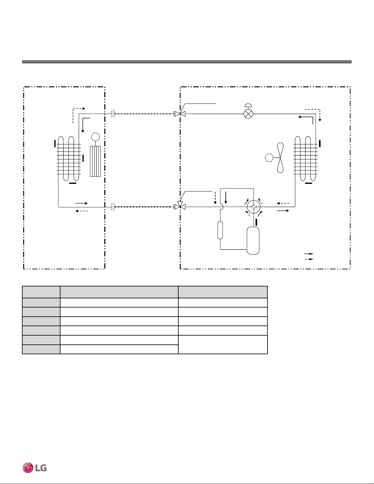
REFRIGERANT FLOW DIAGRAMS
Mega Inverter LSN/LSU090-120HEV1
Thermistor Description PCB Connector
TH1
Indoor air temperature thermistor CN-TH1 (Indoor)
TH2
Water level sensor (optional) CN-TH2 (Indoor)
TH3
Evaporator middle temperature thermistor CN-TH3 (Indoor)
TH4
Discharge pipe temperature thermistor CN-TH2 (Outdoor)
TH5
Outdoor air temperature thermistor
CN-TH1 (Outdoor)
TH6
Condensing temperature thermistor
FIELD PIPING
(Ø 1/ 4" Copper Tubing)
FIELD PIPING
(Ø 3/ 8" Copper Tubi ng)
M
M
He at
Exchanger
(Evaporator)
Heat
Exchanger
(Condenser)
Compressor
Accumula to r
2-Way Valve
Reversing
Valve
Indoor Unit Outdoor Unit
: Cooling
: Heating
EEV
TH1
TH3
TH2
TH5
TH4
TH6
Liquid Side
Gas Side
3-
Way Valv e
26 | PRODUCT DATA
Single Zone Mega Wall Mounted Engineering Manual
Due to our policy of continuous product innovation, some specications may change without notication.
©
LG Electronics U.S.A., Inc., Englewood Cliffs, NJ. All rights reserved. “LG ” is a registered trademark of LG Corp.
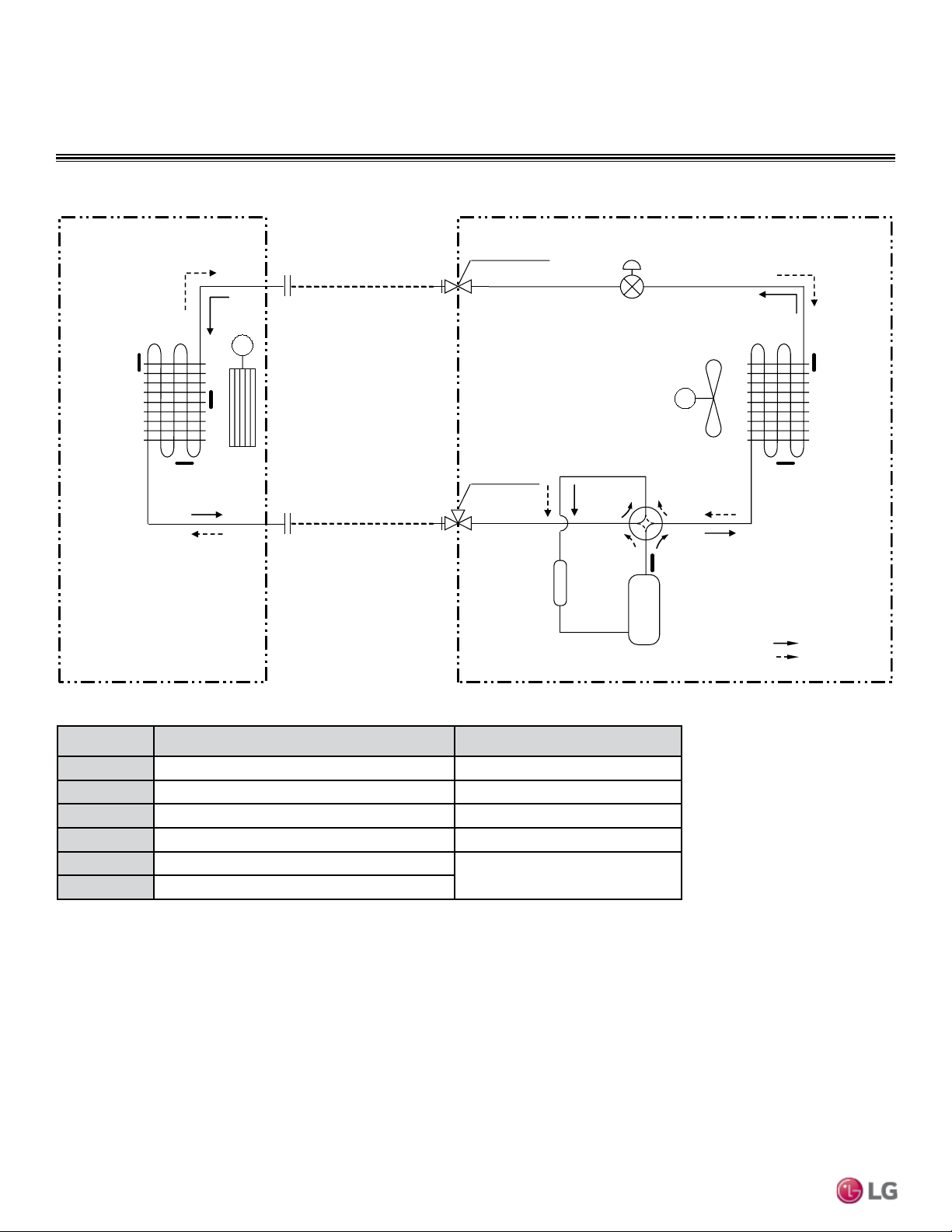
Thermistor Description PCB Connector
TH1
Indoor air temperature thermistor CN-TH1 (Indoor)
TH2
Water level sensor (optional) CN-TH2 (Indoor)
TH3
Evaporator middle temperature thermistor CN-TH3 (Indoor)
TH4
Discharge pipe temperature thermistor CN-TH2 (Outdoor)
TH5
Outdoor air temperature thermistor
CN-TH1 (Outdoor)
TH6
Condensing temperature thermistor
REFRIGERANT FLOW DIAGRAMS
Mega Inverter LSN/LSU180HEV1
FIELD PIPING
(Ø 1/ 4" Copper Tubing)
FIELD PIPING
(Ø 1/ 2" Copper Tubi ng)
M
M
He at
Exchanger
(Evaporator)
Heat
Exchanger
(Condenser)
Compressor
Accumulator
2-Way Valve
Reversing
Va lv e
Indoor Unit Outdoor Unit
: Cooling
: Heating
EEV
TH1
TH3
TH2
TH5
TH4
TH6
Liquid Side
Gas Side
3-
Way Valv e

PRODUCT DATA | 27
Product Data
Due to our policy of continuous product innovation, some specications may change without notication.
©
LG Electronics U.S.A., Inc., Englewood Cliffs, NJ. All rights reserved. “LG ” is a registered trademark of LG Corp.
Thermistor Description PCB Connector
TH1
Indoor air temperature thermistor CN-TH1 (Indoor)
TH2
Water level sensor (optional) CN-TH2 (Indoor)
TH3
Evaporator middle temperature thermistor CN-TH3 (Indoor)
TH4
Discharge pipe temperature thermistor CN-TH2 (Outdoor)
TH5
Outdoor air temperature thermistor
CN-TH1 (Outdoor)
TH6
Condensing temperature thermistor
REFRIGERANT FLOW DIAGRAMS
Mega Inverter LSN/LSU240HEV1
FIELD PIPING
(Ø 1/ 4" Copper Tubing)
FIELD PIPING
(Ø 5/ 8" Copper Tubi ng)
M
M
Heat
Exchanger
(Evaporator)
Heat
Exchanger
(Condenser)
Compressor
Accumulator
2-Way Valve
Reversing
Valv e
Indoor Unit Outdoor Unit
: Cooling
: Heating
EEV
TH1
TH3
TH2
TH5
TH4
TH6
Liquid Side
Gas Side
3-
Way Valv e
28 | PRODUCT DATA
Single Zone Mega Wall Mounted Engineering Manual
Due to our policy of continuous product innovation, some specications may change without notication.
©
LG Electronics U.S.A., Inc., Englewood Cliffs, NJ. All rights reserved. “LG ” is a registered trademark of LG Corp.
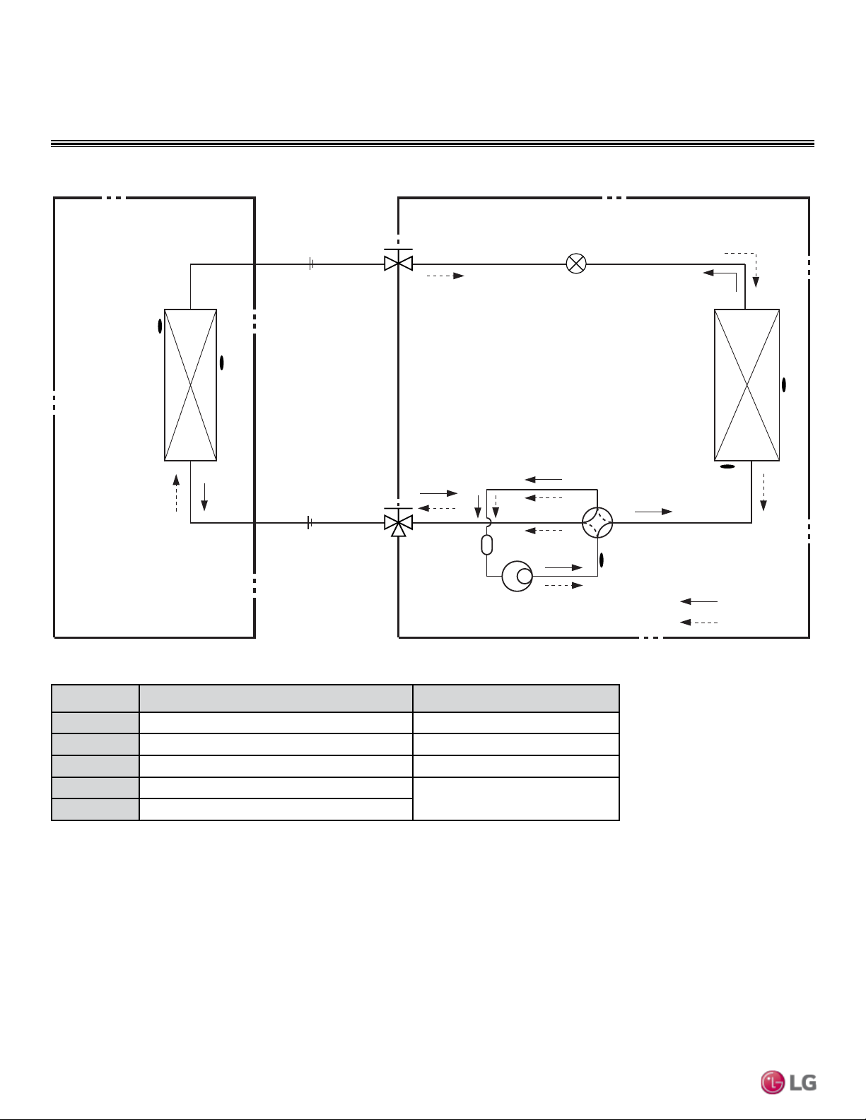
REFRIGERANT FLOW DIAGRAMS
Mega 115V LSN/LSU090-120HXV
Thermistor Description PCB Connector
TH1
Indoor air temperature thermistor CN-TH1 (Indoor)
TH2
Evaporator middle temperature thermistor CN-TH2 (Indoor)
TH3
Discharge pipe temperature thermistor CN-TH2 (Outdoor)
TH4
Condensing middle temperature thermistor
CN-TH1 (Outdoor)
TH5
Outdoor air temperature thermistor
tinU roodtuOtinU roodnI
Heat
Exchanger
(Evaporator)
Heat
Exchanger
(Condenser)
Compressor
Accumulator
Gas Side
3-Way Valve
2-Way Valve
Liquid Side
Cooling
Heating
Reversing Valve
EEV
FIELD PIPING
(Ø 1/4" Copper Tubing)
FIELD PIPING
(Ø 3/8" Copper Tubing)
TH1
TH4
TH5
TH2
TH3
PRODUCT DATA | 29
Product Data
Due to our policy of continuous product innovation, some specications may change without notication.
©
LG Electronics U.S.A., Inc., Englewood Cliffs, NJ. All rights reserved. “LG ” is a registered trademark of LG Corp.
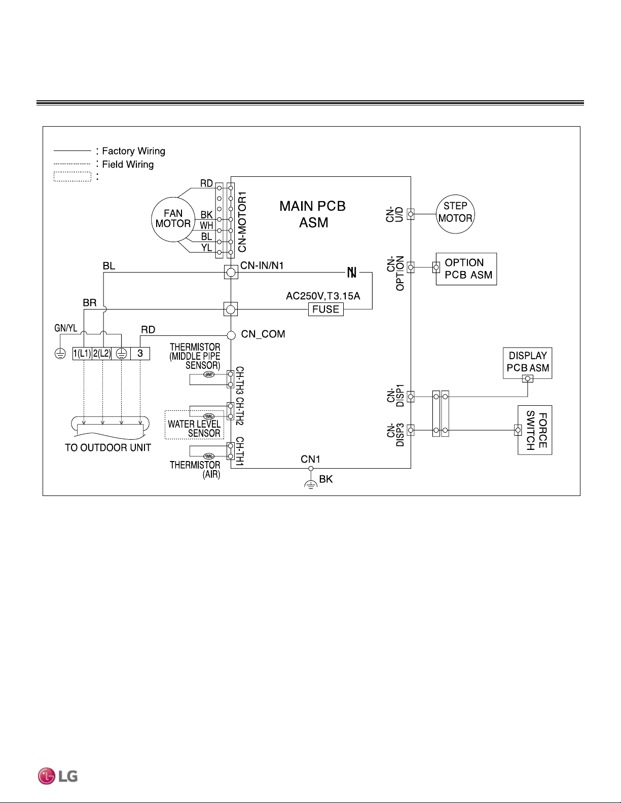
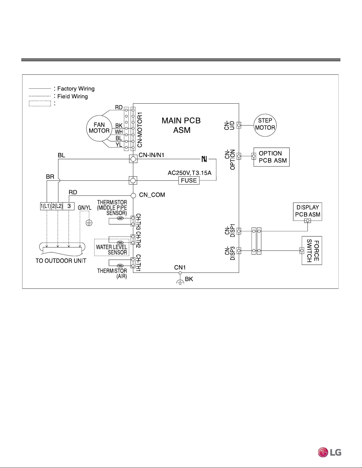
WIRING DIAGRAM
Inverter Singl
Option
CN-L1
Mega Inverter LSN090HEV1
30 | PRODUCT DATA
Single Zone Mega Wall Mounted Engineering Manual
Due to our policy of continuous product innovation, some specications may change without notication.
©
LG Electronics U.S.A., Inc., Englewood Cliffs, NJ. All rights reserved. “LG ” is a registered trademark of LG Corp.
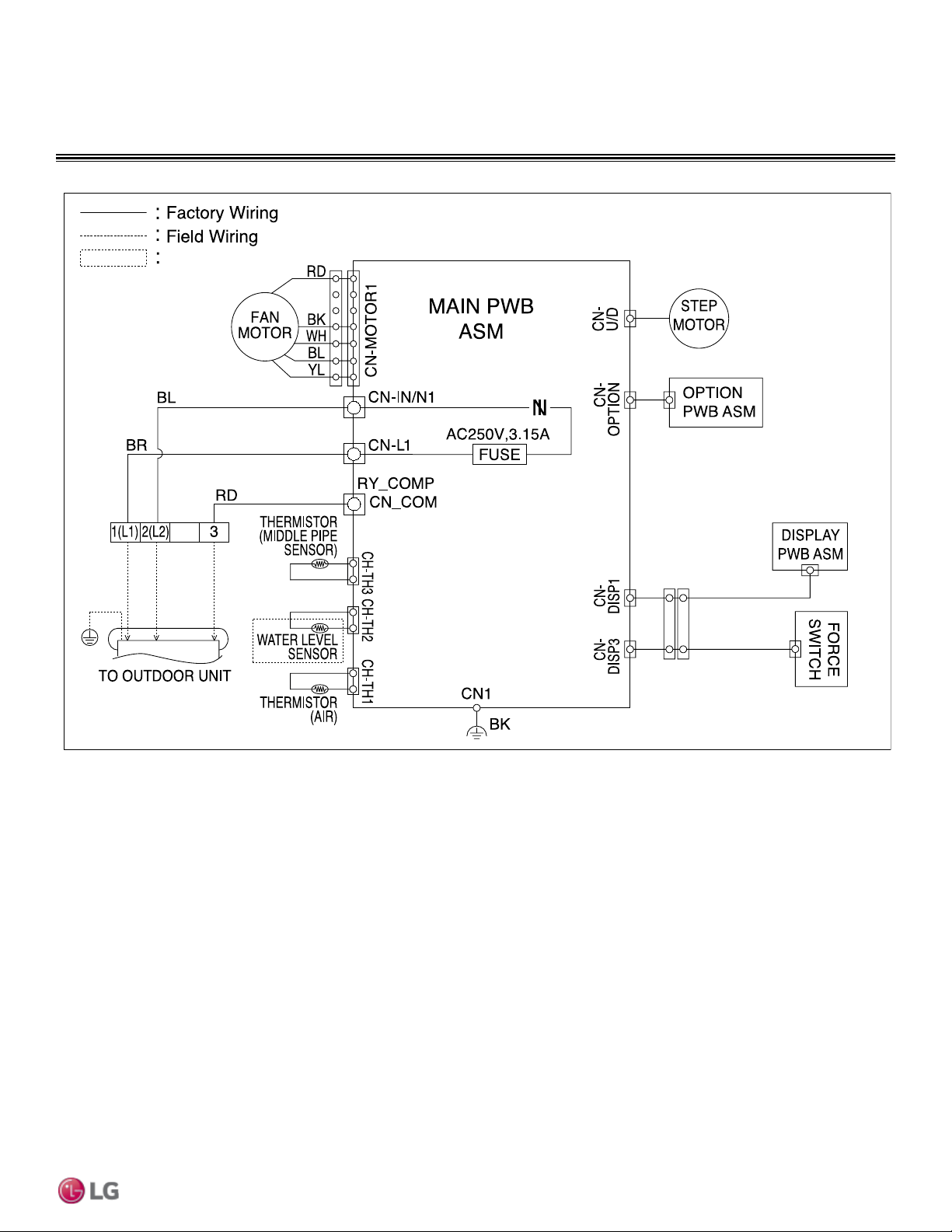
WIRING DIAGRAM
Mega Inverter LSN120HEV1
Option
CN-L1
PRODUCT DATA | 31
Product Data
Due to our policy of continuous product innovation, some specications may change without notication.
©
LG Electronics U.S.A., Inc., Englewood Cliffs, NJ. All rights reserved. “LG ” is a registered trademark of LG Corp.
WIRING DIAGRAM
Mega Inverter LSN180HEV1 and LSN240HEV1
Option
32 | PRODUCT DATA
Single Zone Mega Wall Mounted Engineering Manual
Due to our policy of continuous product innovation, some specications may change without notication.
©
LG Electronics U.S.A., Inc., Englewood Cliffs, NJ. All rights reserved. “LG ” is a registered trademark of LG Corp.
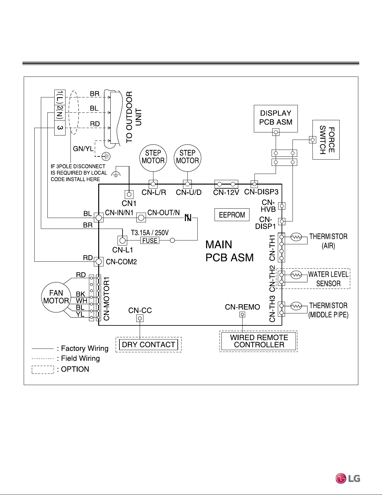
WIRING DIAGRAM
Mega 115V LSN090HXV and LSN120HXV
PRODUCT DATA | 33
Product Data
Due to our policy of continuous product innovation, some specications may change without notication.
©
LG Electronics U.S.A., Inc., Englewood Cliffs, NJ. All rights reserved. “LG ” is a registered trademark of LG Corp.
WIRING DIAGRAM
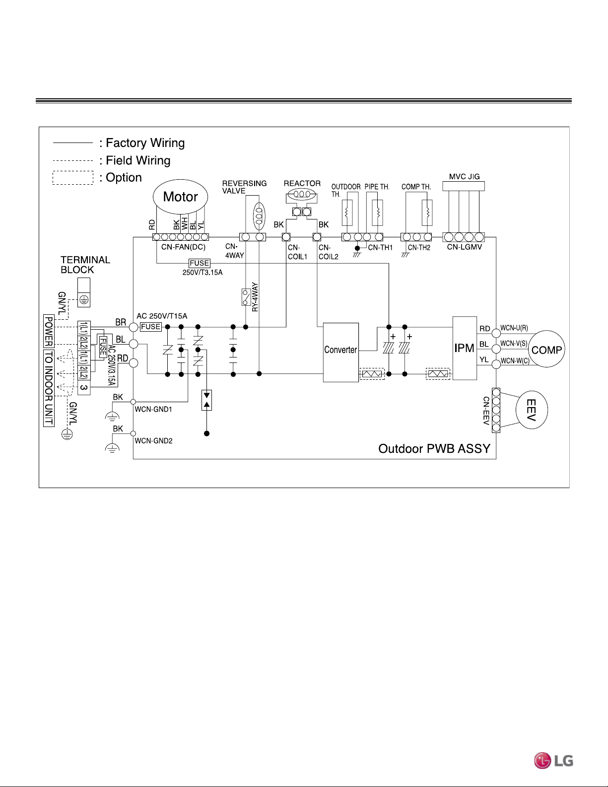
Mega Inverter LSU090HEV1 and LSU120HEV1
Option
34 | PRODUCT DATA
Single Zone Mega Wall Mounted Engineering Manual
Due to our policy of continuous product innovation, some specications may change without notication.
©
LG Electronics U.S.A., Inc., Englewood Cliffs, NJ. All rights reserved. “LG ” is a registered trademark of LG Corp.
WIRING DIAGRAM
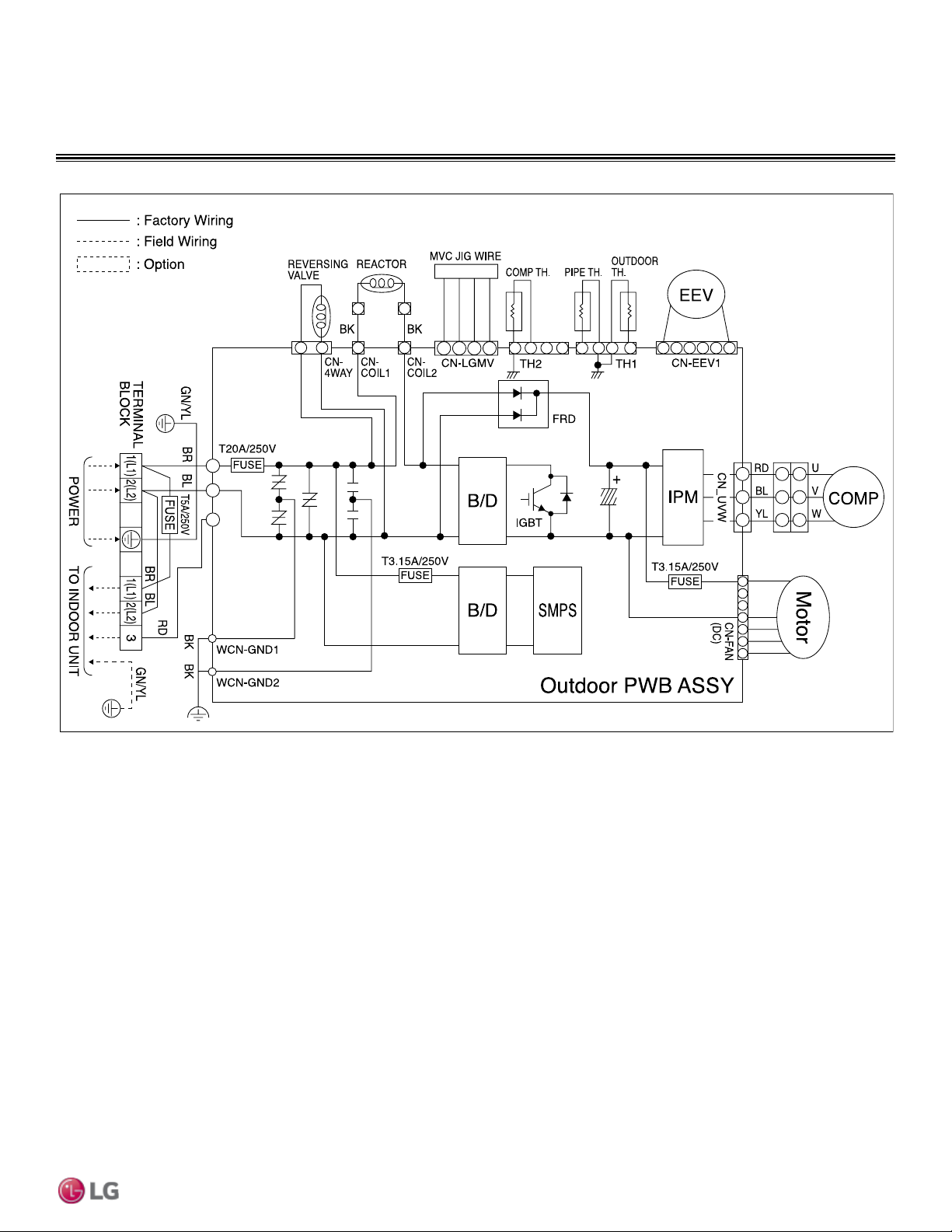
Mega Inverter LSU180HEV1
PRODUCT DATA | 35
Product Data
Due to our policy of continuous product innovation, some specications may change without notication.
©
LG Electronics U.S.A., Inc., Englewood Cliffs, NJ. All rights reserved. “LG ” is a registered trademark of LG Corp.
WIRING DIAGRAM
Mega Inverter LSU240HEV1
36 | PRODUCT DATA
Single Zone Mega Wall Mounted Engineering Manual
Due to our policy of continuous product innovation, some specications may change without notication.
©
LG Electronics U.S.A., Inc., Englewood Cliffs, NJ. All rights reserved. “LG ” is a registered trademark of LG Corp.
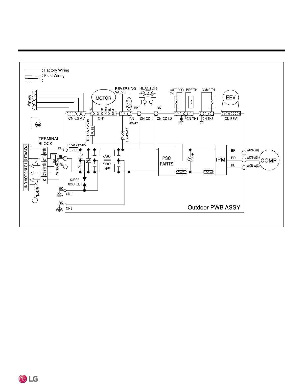
WIRING DIAGRAM
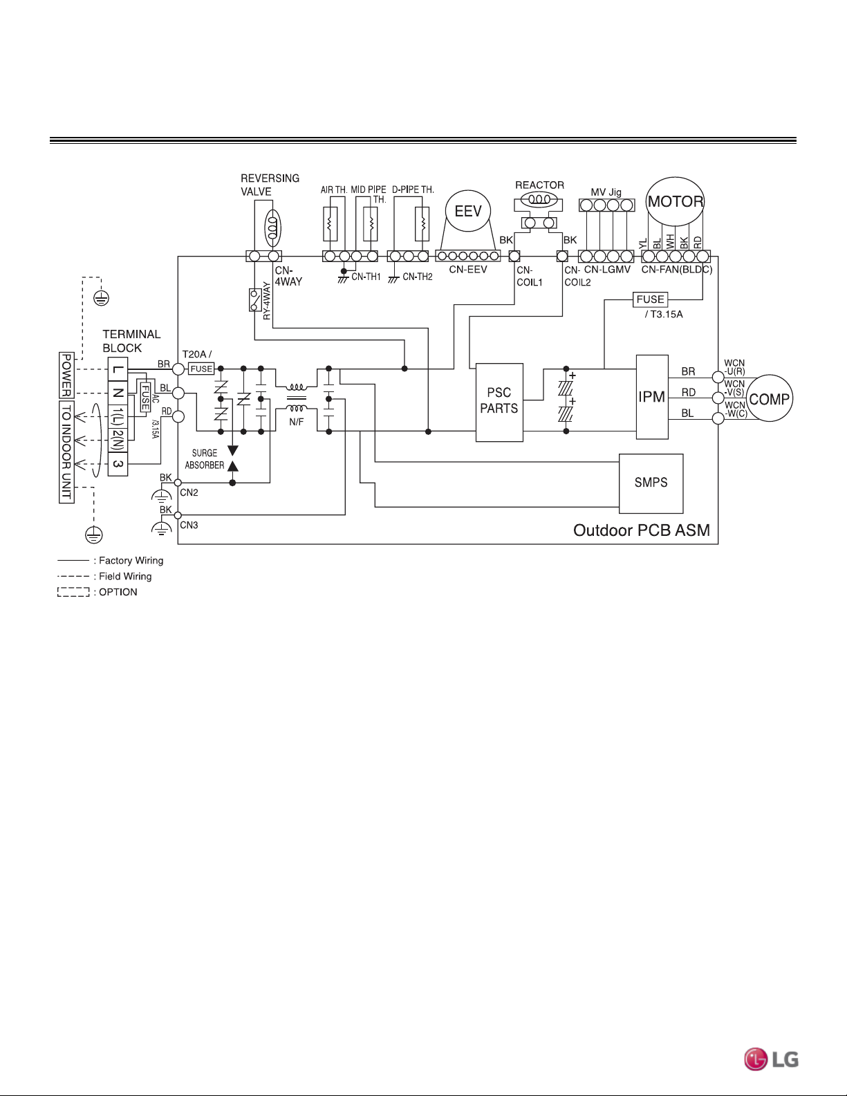
Mega 115V LSU090HXV and LSU120HXV
250V
250V
250V
PRODUCT DATA | 37
Product Data
Due to our policy of continuous product innovation, some specications may change without notication.
©
LG Electronics U.S.A., Inc., Englewood Cliffs, NJ. All rights reserved. “LG ” is a registered trademark of LG Corp.
ACCESSORIES
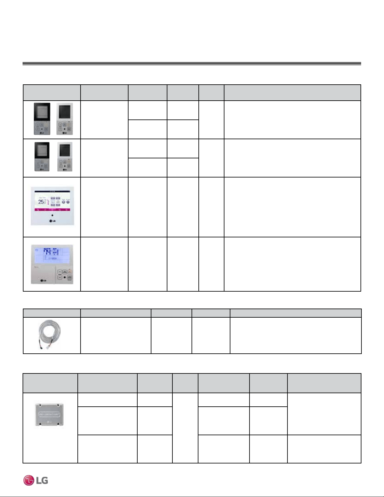
Table 9: Optional Zone Controllers for Mega 115 HXV Systems (see page 14 for Functions, Controls and Options).
Before specifying or placing an order, refer to the V-Net Network Solution Engineering Product Data Book and review the detailed technical data provided to fully understand the capabilities / limitations of these devices.
Zone Controller Name Model No. Case Color
Max Wire
Length (ft)
Description
Simple Controller
with mode selection
PQRCVCL0Q Black
164
Allows control of indoor unit on/off, operation mode, fan speed,
and temperature setpoint for up to 16 indoor units.
PQRCVCL0QW White
Simple Controller
without mode
selection
PQRCHCA0Q Black
164
Allows control of indoor unit on/off, fan speed, and temperature
setpoint for up to 16 indoor units.
PQRCHCA0QW White
LG Premium
Controller
PREMTA000 Ivory 164
Allows control of indoor unit on/off, operation mode, occupied/
unoccupied temperature setpoints, fan speed, and air flow
direction for up to 16 indoor units. Programmable schedule with
5 events per day with control of occupied/unoccupied, on/
off, mode, setpoints and fan speed. Advanced functions
include two setpoint autochangeover, minimum difference
between setpoints, setback, timed override, target energy
consumption display, check energy display and master/slave.
LG Programmable
Thermostat
PREMTB10U White 164
Allows control of indoor unit on/off, operation mode, occupied
and unoccupied temperature setpoints, fan speed, and airflow
direction for up to 16 indoor units. Programmable schedule
with 5 events per day with control of occupied/unoccupied, on/
off, mode, setpoints and fan speed. Advanced functions include
two setpoint auto changeover, minimum difference between
setpoints, setback and timed override.
Table 10: Zone Controller Communication Cables.
Communication Cable Name Model No. Wire Length (ft) Description
Wired Remote/Group Control
Extension Cable
PZCWRC1 33
Increases the distance between a remote controller and an
indoor unit or between indoor units in a control group.
Table 11: Speciality Application Devices for Mega 115V HXV Systems (see page 14 for Functions, Controls and Options)..
Speciality Application
Device
Name Model No.
Connect
to
Application
Binary
Signals Input/
Output
Description
Simple Dry Contact PQDSB1
Indoor
Unit
On/Off, Run Status,
Error Status
1/2
Enables the indoor unit to be
controlled and monitored by third
party controls using binary inputs
and outputs.
Dry Contact Unit for
Economizer, occupied/
unoccupied
PQDSBC1
On/Off, Mode,
Controller Lock, Power
Save, Run Status,
Error Status
2/2
Dry Contact Unit for 24V
Thermostat
PDRYCB300
On/Off, Thermo On/
Off, Mode, Fan Speed,
Run Status, Error
Status
---
Enables the indoor unit to be
controlled and monitored by a
third party thermostat or
controller.
Before specifying or placing an order, refer to the V-Net Network Solution Engineering Product Data Book and review the detailed technical data provided to fully understand the capabilities / limitations of these devices.
Before specifying or placing an order, refer to the V-Net Network Solution Engineering Product Data Book and review the detailed technical data provided to fully understand the capabilities / limitations of these devices.
38 | PRODUCT DATA
Single Zone Mega Wall Mounted Engineering Manual
Due to our policy of continuous product innovation, some specications may change without notication.
©
LG Electronics U.S.A., Inc., Englewood Cliffs, NJ. All rights reserved. “LG ” is a registered trademark of LG Corp.
ACCESSORIES
• Actual inverter compressor speed
• Target inverter compressor speed
• Actual outdoor fan speed
• Target outdoor unit fan speed
• Actual superheat
• Inverter compressor current value
• Outdoor air temperature
• Actual high pressure/saturation temperature
• Actual low pressure/saturation temperature
• Suction temperature
• Inverter compressor discharge temperature
• Outdoor coil pipe temperature
• Liquid line pipe temperature
• Inverter compressor operation indicator
light
• Four-way reversing valve operation
indicator light
• Pressure graph showing actual low pres-
sure and actual high pressure levels
• Error code display
• Operating mode indicator
• Total number of connected indoor units (for
multi zone systems)
• Communication indicator lights
• Unit error code
• Indoor unit capacity
• Indoor unit operating mode
• Indoor unit fan speed
• Indoor unit room temperature
• Indoor unit inlet pipe temperature
• Indoor unit outlet pipe temperature
LG Monitoring View (LGMV) Diagnostic Software and Cable
(PRCTSL1 and PRCTFE1)
LGMV software allows the service technician or commissioning agent to connect a computer
USB port to the outdoor unit main printed circuit board (PCB) using an accessory cable with-
out the need for a separate interface device. The main screen for LGMV shall allow user to
view the following real time data on one screen:
Additional screens can be accessed by tabs on the main screen:
1. Cycleview: Graphic of internal components including:
2. Setting: Converts metric values to imperial values.
3. Making Data: Recording of real time data to a separate file created to be stored on the
user’s computer.
4. Loading Data: Recorded data from a saved “.CSV” file can be loaded to create an LGMV
session.
5. Electrical Data: The lower half of main screen is changed to show the following:
• Compressors showing actual speeds
• EEVs
• IDUs
• Low and high pressures
• Temperature and pressure sensors
• Four-way reversing valve
• Outdoor fans showing status and speeds
• Inverter compressor
- Amps
- Volts
-
Power Hz
- Inverter control board fan Hz
The software is available in a high version with all of the features listed above. The low version has all features as the high version without
Target High Pressure and Target Low Pressure values shown on main screen.
In lieu of connecting to the ODU, user has the option to connect to IDU with the use of a USB to RS-485 connector kit. When connected
through IDU, user will not be able to record data.
This software can be used to both commission new systems and troubleshoot existing systems. LGMV data can be recorded to a “.CSV” file
and emailed to an LG representative to assist with diagnostic evaluations.
Recommended Minimum PC Configuration:
• CPU: Pentium
®
IV 1.6 GHz
• Operating System: Windows
®
NT/2000/
XP/Vista
• Main Memory: 256 MB
• Hard Disk: 600 MB when operating
• Web Browser: Internet Explorer
®
5.0

“Cooling Capacity Data” on page 40
“Heating Capacity Data” on page 43
PERFORMANCE DATA
40 | PRODUCT DATA
Single Zone Mega Wall Mounted Engineering Manual
Due to our policy of continuous product innovation, some specications may change without notication.
©
LG Electronics U.S.A., Inc., Englewood Cliffs, NJ. All rights reserved. “LG ” is a registered trademark of LG Corp.
PERFORMANCE DATA
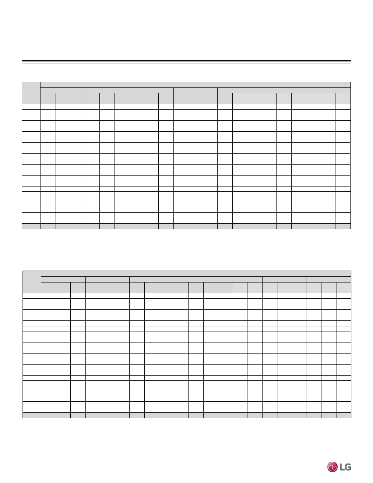
Table 11: LSN090HEV1/LSU120HEV1 Cooling Capacities.
Outdoor
Air
Temp.
(°F DB)
Indoor Air Temperature (°F DB/ °F WB)
64 / 53 68 / 57 72 / 61 77 / 64 80 / 67 86 / 72 90 / 75
TC SHC PI TC SHC PI TC SHC PI TC SHC PI TC SHC PI TC SHC PI TC SHC PI
14 5.20 4.11 0.29 5.59 4.41 0.30 5.98 4.72 0.31 6.37 5.03 0.32 6.55 5.17 0.33 7.15 5.64 0.34 7.54 5.95 0.35
23 5.59 4.41 0.29 6.00 4.74 0.30 6.42 5.07 0.31 6.84 5.40 0.31 7.03 5.55 0.32 7.68 6.06 0.34 8.10 6.39 0.35
25 5.67 4.47 0.29 6.08 4.80 0.30 6.50 5.13 0.31 6.92 5.46 0.32 7.11 5.61 0.33 7.76 6.12 0.34 8.18 6.45 0.35
30 5.89 4.64 0.32 6.31 4.98 0.32 6.74 5.32 0.33 7.15 5.64 0.34 7.35 5.80 0.36 8.00 6.31 0.37 8.45 6.67 0.38
35 6.11 4.82 0.34 6.55 5.16 0.35 6.98 5.51 0.36 7.39 5.83 0.37 7.59 5.99 0.38 8.24 6.50 0.39 8.72 6.88 0.41
40 6.33 4.99 0.36 6.78 5.35 0.37 7.23 5.70 0.38 7.62 6.01 0.39 7.83 6.18 0.40 8.49 6.70 0.42 8.99 7.09 0.43
45 6.55 5.17 0.38 7.01 5.53 0.39 7.47 5.89 0.40 7.85 6.19 0.42 8.07 6.37 0.43 8.73 6.89 0.45 9.26 7.31 0.46
50 6.77 5.34 0.40 7.24 5.71 0.41 7.71 6.08 0.43 8.08 6.38 0.44 8.31 6.56 0.45 8.97 7.08 0.47 9.54 7.52 0.49
55 6.99 5.51 0.42 7.47 5.89 0.44 7.95 6.27 0.45 8.31 6.56 0.46 8.55 6.74 0.48 9.22 7.27 0.50 9.81 7.74 0.51
60 7.21 5.69 0.44 7.70 6.07 0.46 8.19 6.46 0.47 8.55 6.74 0.49 8.79 6.93 0.50 9.46 7.46 0.52 10.08 7.95 0.54
65 7.43 5.86 0.47 7.93 6.26 0.48 8.43 6.65 0.50 8.78 6.93 0.51 9.03 7.12 0.53 9.70 7.65 0.55 10.35 8.17 0.56
70 7.65 6.04 0.49 8.16 6.44 0.50 8.67 6.84 0.52 9.01 7.11 0.53 9.27 7.31 0.55 9.95 7.85 0.57 10.63 8.38 0.59
75 7.55 5.96 0.50 8.06 6.36 0.52 8.58 6.77 0.53 8.93 7.04 0.55 9.18 7.24 0.57 9.82 7.75 0.59 10.54 8.32 0.61
80 7.35 5.80 0.52 7.86 6.21 0.54 8.38 6.61 0.56 8.76 6.91 0.57 9.10 7.18 0.59 9.69 7.65 0.62 10.37 8.18 0.63
85 7.16 5.65 0.56 7.67 6.05 0.58 8.18 6.45 0.60 8.59 6.77 0.61 8.93 7.04 0.63 9.56 7.54 0.66 10.21 8.06 0.68
90 6.96 5.49 0.58 7.47 5.89 0.60 7.98 6.30 0.62 8.42 6.64 0.64 8.76 6.91 0.66 9.44 7.44 0.69 10.01 7.90 0.71
95 6.75 5.33 0.60 7.26 5.73 0.62 7.76 6.12 0.64 8.27 6.52 0.66 8.50 6.71
0.68 9.28 7.32 0.71 9.78 7.72 0.73
100 6.57 5.19 0.61 7.08 5.59 0.63 7.59 5.99 0.65 8.09 6.38 0.67 8.39 6.62 0.69 9.10 7.18 0.72 9.61 7.58 0.74
105 6.40 5.05 0.62 6.90 5.45 0.64 7.41 5.85 0.66 7.91 6.24 0.68 8.28 6.53 0.70 8.93 7.04 0.73 9.43 7.44 0.75
110 6.22 4.91 0.63 6.73 5.31 0.65 7.23 5.71 0.67 7.74 6.11 0.69 8.10 6.39 0.71 8.75 6.90 0.74 9.25 7.30 0.76
115 6.04 4.77 0.64 6.55 5.17 0.65 7.06 5.57 0.68 7.56 5.97 0.70 7.93 6.25 0.72 8.57 6.76 0.75 9.08 7.16 0.77
118 5.87 4.63 0.64 6.38 5.03 0.66 6.80 5.37 0.68 7.31 5.77 0.70 7.65 6.04 0.72 8.29 6.54 0.75 8.76 6.91 0.78
122 5.59 4.41 0.64 6.07 4.79 0.66 6.54 5.16 0.68 7.02 5.54 0.71 7.37 5.81 0.73 7.98 6.30 0.76 8.46 6.67 0.78
Table 12: LSN120HEV1/LSU120HEV1 Cooling Capacities.
Outdoor
Air
Temp.
(°F DB)
Indoor Air Temperature (°F DB/ °F WB)
64 / 53 68 / 57 72 / 61 77 / 64 80 / 67 86 / 72 90 / 75
TC SHC PI TC SHC PI TC SHC PI TC SHC PI TC SHC PI TC SHC PI TC SHC PI
14 7.35 5.50 0.48 7.90 5.91 0.50 8.45 6.33 0.51 9.00 6.74 0.53 9.25 6.93 0.55 10.10 7.56 0.57 10.65 7.97 0.59
23 7.89 5.91 0.48 8.48 6.35 0.50 9.07 6.79 0.51 9.66 7.23 0.53 9.93 7.44 0.54 10.84 8.12 0.57 11.43 8.56 0.58
25 8.00 5.99 0.49 8.59 6.43 0.51 9.18 6.88 0.52 9.77 7.32 0.54 10.04 7.52 0.55 10.95 8.20 0.58 11.54 8.65 0.59
30 8.31 6.22 0.53 8.92 6.68 0.54 9.52 7.13 0.56 10.10 7.56 0.58 10.38 7.77 0.60 11.30 8.46 0.62 11.93 8.93 0.64
35 8.62 6.46 0.56 9.24 6.92 0.58 9.86 7.39 0.60 10.43 7.81 0.62 10.72 8.03 0.64 11.64 8.72 0.66 12.31 9.22 0.68
40 8.93 6.69 0.60 9.57 7.17 0.62 10.20 7.64 0.64 10.75 8.05 0.66 11.05 8.28 0.68 11.98 8.97 0.70 12.70 9.51 0.73
45 9.24 6.92 0.64 9.89 7.41 0.66 10.54 7.89 0.68 11.08 8.30 0.70 11.39 8.53 0.72 12.32 9.23 0.75 13.08 9.80 0.77
50 9.56 7.16 0.67 10.22 7.65 0.69 10.88 8.15 0.72 11.41 8.55 0.74 11.73 8.79 0.76 12.67 9.49 0.79 13.46 10.08 0.81
55 9.87 7.39 0.71 10.54 7.90 0.73 11.22 8.40 0.75 11.74 8.79 0.78 12.07 9.04 0.80 13.01 9.74 0.83 13.85 10.37 0.86
60 10.18 7.62 0.75 10.87 8.14 0.77 11.56 8.66 0.79 12.06 9.04 0.82 12.40 9.29 0.84 13.35 10.00 0.88 14.23 10.66 0.90
65 10.49 7.86 0.78 11.19 8.38 0.81 11.90 8.91 0.83 12.39 9.28 0.86 12.74 9.54 0.88 13.70 10.26 0.92 14.62 10.95 0.95
70 10.80 8.09 0.82 11.52 8.63 0.84 12.24 9.17 0.87 12.72 9.53 0.90 13.08 9.80 0.92 14.04 10.52 0.96 15.00 11.24 0.99
75 10.66 7.99 0.84 11.38 8.53 0.87 12.11 9.07 0.89 12.60 9.44 0.92 12.96 9.71 0.95 13.86 10.38 0.99 14.88 11.15 1.02
80 10.38 7.78 0.88 11.10 8.32 0.91 11.82 8.86 0.93 12.36 9.26 0.96 12.84 9.62 0.99 13.68 10.25 1.03 14.64 10.97 1.06
85 10.11 7.57 0.94 10.83 8.11 0.97 11.54 8.65 1.00 12.12 9.08 1.03 12.60 9.44 1.06 13.50 10.11 1.10 14.42 10.80 1.14
90 9.83 7.36 0.98 10.55 7.90 1.01 11.26 8.44 1.04 11.88 8.90 1.07 12.36 9.26 1.11 13.32 9.98 1.15 14.13 10.59 1.18
95 9.53 7.14 1.01 10.25 7.67 1.04 10.96 8.21 1.07 11.67 8.74 1.11 12.00 8.99
1.14 13.10 9.81 1.19 13.81 10.35 1.22
100 9.28 6.95 1.03 10.00 7.49 1.06 10.71 8.02 1.09 11.42 8.56 1.12 11.84 8.87 1.16 12.85 9.63 1.21 13.56 10.16 1.24
105 9.03 6.77 1.04 9.75 7.30 1.08 10.46 7.83 1.11 11.17 8.37 1.14 11.69 8.76 1.18 12.60 9.44 1.23 13.31 9.97 1.26
110 8.78 6.58 1.05 9.50 7.11 1.09 10.21 7.65 1.12 10.92 8.18 1.16 11.44 8.57 1.19 12.35 9.25 1.24 13.07 9.79 1.28
115 8.53 6.39 1.06 9.25 6.93 1.10 9.96 7.46 1.13 10.67 8.00 1.17 11.19 8.38 1.20 12.10 9.06 1.25 12.82 9.60 1.29
118 8.28 6.20 1.07 9.00 6.74 1.11 9.60 7.19 1.14 10.32 7.73 1.18 10.80 8.09 1.21 11.70 8.76 1.26 12.36 9.26 1.30
122 7.89 5.91 1.08 8.56 6.41 1.11 9.24 6.92 1.15 9.91 7.43 1.18 10.40 7.79 1.22 11.27 8.44 1.27 11.94 8.94 1.31
DB: Dry Bulb Temperature (°F) WB: Wet Bulb Temperature (°F) TC: Total Capacity (kBtu/h)
SHC: Sensible Capacity (kBtu/h) PI: Power Input (kW) (includes compressor,indoor fan motor and
outdoor fan motor)
1. All capacities are net, evaporator fan motor heat is deducted.
2. Grey shading indicates reference data. When operating the unit at this temperature, these values
can be different by discontinuous operation.
3. Direct interpolation is permissible. Do not extrapolate.
Nominal capacity as rated: 0 ft. above sea level with 25 ft. of refrigerant piping.
0 ft. level difference between outdoor and indoor units.
Nominal cooling capacity rating obtained with air entering the indoor unit at 80ºF dry bulb (DB) and
67ºF wet bulb (WB), and outdoor ambient conditions of 95ºF dry bulb (DB) and 75ºF wet bulb (WB).
Cooling Capacity
LS090HEV1, LS120HEV1
PRODUCT DATA | 41
Product Data
Due to our policy of continuous product innovation, some specications may change without notication.
©
LG Electronics U.S.A., Inc., Englewood Cliffs, NJ. All rights reserved. “LG ” is a registered trademark of LG Corp.
PERFORMANCE DATA
Cooling Capacity
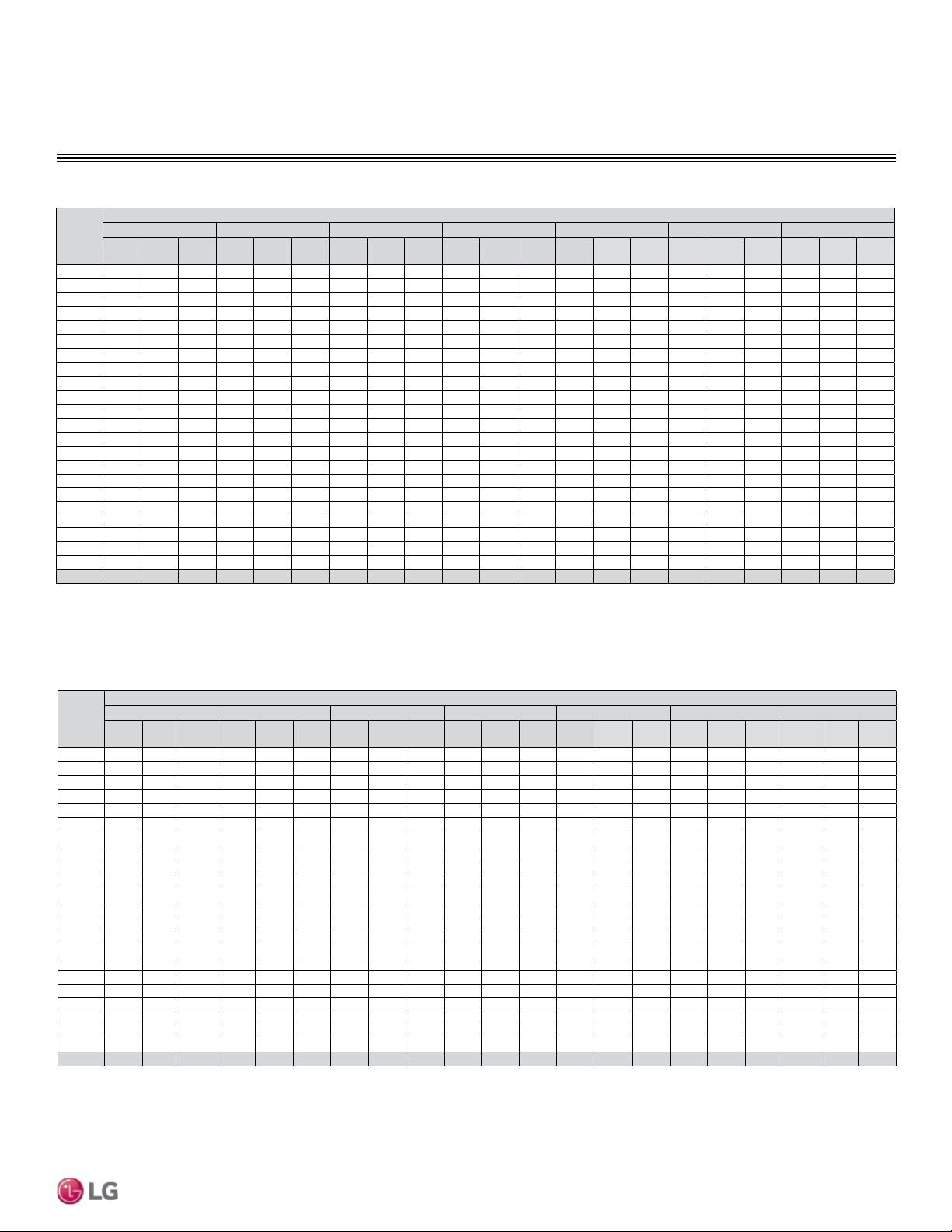
Table 13: LSN0180HEV1/LSU180HEV1 Cooling Capacities.
Outdoor
Air
Temp.
(°F DB)
Indoor Air Temperature (°F DB/ °F WB)
64 / 53 68 / 57 72 / 61 77 / 64 80 / 67 86 / 72 90 / 75
TC SHC PI TC SHC PI TC SHC PI TC SHC PI TC SHC PI TC SHC PI TC SHC PI
14 10.41 8.12 6.58 11.19 8.73 6.78 11.97 9.33 6.99 12.75 9.94 7.21 13.10 10.22 7.43 14.30 11.16 7.73 15.08 11.76 7.96
23 11.17 8.72 6.55 12.01 9.37 6.75 12.85 10.02 6.96 13.68 10.67 7.18 14.07 10.97 7.40 15.36 11.98 7.70 16.19 12.63 7.93
25 11.33 8.84 6.69 12.17 9.49 6.89 13.01 10.14 7.10 13.84 10.80 7.32 14.23 11.10 7.54 15.52 12.10 7.84 16.35 12.75 8.07
30 11.77 9.18 7.18 12.63 9.85 7.40 13.49 10.52 7.63 14.31 11.16 7.86 14.70 11.47 8.10 16.00 12.48 8.42 16.90 13.18 8.67
35 12.21 9.53 7.68 13.09 10.21 7.91 13.97 10.90 8.15 14.77 11.52 8.40 15.18 11.84 8.66 16.49 12.86 9.00 17.44 13.60 9.26
40 12.65 9.87 8.17 13.55 10.57 8.42 14.45 11.27 8.67 15.23 11.88 8.94 15.66 12.22 9.21 16.97 13.24 9.58 17.98 14.03 9.86
45 13.10 10.21 8.66 14.01 10.93 8.93 14.93 11.65 9.20 15.70 12.25 9.48 16.14 12.59 9.77 17.46 13.62 10.16 18.53 14.45 10.46
50 13.54 10.56 9.15 14.47 11.29 9.43 15.41 12.02 9.72 16.16 12.61 10.02 16.62 12.96 10.33 17.95 14.00 10.74 19.07 14.88 11.06
55 13.98 10.90 9.64 14.94 11.65 9.94 15.90 12.40 10.25 16.63 12.97 10.56 17.10 13.33 10.89 18.43 14.38 11.32 19.62 15.30 11.66
60 14.42 11.25 10.14 15.40 12.01 10.45 16.38 12.77 10.77 17.09 13.33 11.10 17.57 13.71 11.45 18.92 14.76 11.90 20.16 15.73 12.26
65 14.86 11.59 10.63 15.86 12.37 10.96 16.86 13.15 11.29 17.56 13.69 11.64 18.05 14.08 12.00 19.40 15.14 12.48 20.71 16.15 12.86
70 15.30 11.93 11.12 16.32 12.73 11.46 17.34 13.53 11.82 18.02 14.06 12.18 18.53 14.45 12.56 19.89 15.51 13.06 21.25 16.58 13.46
75 15.10 11.78 11.44 16.13 12.58 11.79 17.15 13.38 12.16 17.85 13.92 12.54 18.36 14.32 12.92 19.64 15.32 13.44 21.08 16.44 13.84
80 14.71 11.47 11.94 15.73 12.27 12.31 16.75 13.07 12.69 17.51 13.66 13.08 18.19 14.19 13.49 19.38 15.12 14.02 20.74 16.18 14.45
85 14.32 11.17 12.76 15.34 11.96 13.16 16.35 12.76 13.56 17.17 13.39 13.98 17.85 13.92 14.42 19.13 14.92 14.99 20.43 15.93 15.44
90 13.93 10.86 13.31 14.94 11.65 13.72 15.96 12.45 14.15 16.83 13.13 14.58 17.51 13.66 15.04 18.87 14.72 15.64 20.02 15.62 16.11
95 13.50 10.53 13.72 14.51 11.32 14.15 15.52 12.11 14.58 16.54 12.90 15.04 17.00 13.26
15.50 18.56 14.48 16.12 19.57 15.26 16.60
100 13.15 10.26 13.95 14.16 11.05 14.38 15.17 11.83 14.83 16.18 12.62 15.29 16.78 13.09 15.76 18.20 14.20 16.39 19.22 14.99 16.88
105 12.80 9.98 14.18 13.81 10.77 14.62 14.82 11.56 15.07 15.83 12.35 15.54 16.56 12.92 16.02 17.85 13.92 16.66 18.86 14.71 17.16
110 12.44 9.71 14.34 13.45 10.49 14.78 14.46 11.28 15.24 15.48 12.07 15.71 16.21 12.64 16.20 17.50 13.65 16.85 18.51 14.44 17.35
115 12.09 9.43 14.48 13.10 10.22 14.92 14.11 11.01 15.39 15.12 11.80 15.86 15.85 12.37 16.35 17.14 13.37 17.01 18.16 14.16 17.52
118 11.73 9.15 14.61 12.75 9.95 15.07 13.60 10.61 15.53 14.62 11.40 16.01 15.30 11.93 16.51 16.58 12.93 17.17 17.51 13.66 17.68
122 11.17 8.71 14.68 12.13 9.46 15.14 13.09 10.21 15.60 14.04 10.95 16.09 14.74 11.49 16.59 15.96 12.45 17.25 16.92 13.19 17.77
Table 14: LSN240HEV1/LSU240HEV1 Cooling Capacities.
Outdoor
Air
Temp.
(°F DB)
Indoor Air Temperature (°F DB/ °F WB)
64 / 53 68 / 57 72 / 61 77 / 64 80 / 67 86 / 72 90 / 75
TC SHC PI TC SHC PI TC SHC PI TC SHC PI TC SHC PI TC SHC PI TC SHC PI
14 13.47 9.92 8.68 14.48 10.67 8.95 15.49 11.41 9.22 16.49 12.15 9.51 16.96 12.49 9.80 18.51 13.64 10.19 19.52 14.38 10.50
23 14.46 10.65 8.64 15.54 11.45 8.91 16.62 12.25 9.19 17.71 13.05 9.47 18.20 13.41 9.76 19.87 14.64 10.15 20.96 15.44 10.46
25 14.66 10.80 8.83 15.75 11.60 9.10 16.83 12.40 9.37 17.91 13.20 9.66 18.41 13.56 9.95 20.08 14.79 10.34 21.16 15.59 10.64
30 15.24 11.23 9.48 16.34 12.04 9.77 17.45 12.86 10.06 18.51 13.64 10.37 19.03 14.02 10.68 20.71 15.26 11.10 21.87 16.11 11.43
35 15.81 11.65 10.13 16.94 12.48 10.44 18.08 13.32 10.75 19.11 14.08 11.08 19.65 14.48 11.42 21.34 15.72 11.87 22.57 16.63 12.22
40 16.38 12.07 10.78 17.54 12.92 11.11 18.70 13.78 11.45 19.72 14.53 11.80 20.27 14.93 12.16 21.97 16.18 12.64 23.27 17.15 13.01
45 16.95 12.49 11.43 18.14 13.36 11.78 19.32 14.24 12.14 20.32 14.97 12.51 20.89 15.39 12.89 22.59 16.65 13.40 23.98 17.67 13.80
50 17.52 12.91 12.07 18.73 13.80 12.45 19.95 14.70 12.83 20.92 15.41 13.22 21.50 15.84 13.63 23.22 17.11 14.17 24.68 18.19 14.59
55 18.09 13.33 12.72 19.33 14.24 13.12 20.57 15.16 13.52 21.52 15.85 13.94 22.12 16.30 14.36 23.85 17.57 14.94 25.39 18.71 15.38
60 18.66 13.75 13.37 19.93 14.68 13.79 21.19 15.62 14.21 22.12 16.30 14.65 22.74 16.76 15.10 24.48 18.04 15.70 26.09 19.22 16.17
65 19.23 14.17 14.02 20.52 15.12 14.46 21.82 16.07 14.90 22.72 16.74 15.36 23.36 17.21 15.84 25.11 18.50 16.47 26.80 19.74 16.96
70 19.80 14.59 14.67 21.12 15.56 15.13 22.44 16.53 15.59 23.32 17.18 16.08 23.98 17.67 16.57 25.74 18.97 17.24 27.50 20.26 17.75
75 19.55 14.40 15.09 20.87 15.38 15.56 22.20 16.35 16.04 23.10 17.02 16.54 23.76 17.51 17.05 25.41 18.72 17.73 27.28 20.10 18.26
80 19.03 14.02 15.75 20.36 15.00 16.24 21.68 15.97 16.74 22.66 16.70 17.26 23.54 17.34 17.79 25.08 18.48 18.50 26.84 19.78 19.06
85 18.53 13.65 16.84 19.85 14.62 17.36 21.16 15.59 17.89 22.22 16.37 18.45 23.10 17.02 19.02 24.75 18.24 19.78 26.44 19.48 20.37
90 18.02 13.28 17.56 19.34 14.25 18.10 20.65 15.22 18.66 21.78 16.05 19.24 22.66 16.70 19.84 24.42 17.99 20.63 25.91 19.09 21.25
95 17.47 12.87 18.10 18.78 13.84 18.66 20.09 14.80 19.24 21.40 15.77 19.84 22.00 16.21
20.45 24.02 17.70 21.27 25.33 18.66 21.91
100 17.02 12.54 18.41 18.33 13.50 18.98 19.63 14.47 19.56 20.94 15.43 20.17 21.71 16.00 20.79 23.56 17.36 21.62 24.87 18.32 22.27
105 16.56 12.20 18.71 17.87 13.17 19.29 19.18 14.13 19.89 20.48 15.09 20.50 21.43 15.79 21.13 23.10 17.02 21.98 24.41 17.99 22.64
110 16.10 11.86 18.92 17.41 12.83 19.50 18.72 13.79 20.11 20.03 14.76 20.73 20.97 15.45 21.37 22.64 16.68 22.23 23.95 17.65 22.89
115 15.64 11.53 19.10 16.95 12.49 19.69 18.26 13.46 20.30 19.57 14.42 20.93 20.52 15.12 21.57 22.19 16.35 22.44 23.50 17.31 23.11
118 15.18 11.18 19.28 16.50 12.16 19.88 17.60 12.97 20.49 18.92 13.94 21.13 19.80 14.59 21.78 21.45 15.80 22.65 22.66 16.70 23.33
122 14.46 10.65 19.37 15.70 11.57 19.97 16.94 12.48 20.59 18.18 13.39 21.23 19.07 14.05 21.88 20.65 15.22 22.76 21.89 16.13 23.44
DB: Dry Bulb Temperature (°F) WB: Wet Bulb Temperature (°F) TC: Total Capacity (kBtu/h)
SHC: Sensible Capacity (kBtu/h) PI: Power Input (kW) (includes compressor,indoor fan motor and
outdoor fan motor)
1. All capacities are net, evaporator fan motor heat is deducted.
2. Grey shading indicates reference data. When operating the unit at this temperature, these values
can be different by discontinuous operation.
3. Direct interpolation is permissible. Do not extrapolate.
Nominal capacity as rated: 0 ft. above sea level with 25 ft. of refrigerant piping.
0 ft. level difference between outdoor and indoor units.
Nominal cooling capacity rating obtained with air entering the indoor unit at 80ºF dry bulb (DB) and
67ºF wet bulb (WB), and outdoor ambient conditions of 95ºF dry bulb (DB) and 75ºF wet bulb (WB).
LS180HEV1, LS240HEV1
42 | PRODUCT DATA
Single Zone Mega Wall Mounted Engineering Manual
Due to our policy of continuous product innovation, some specications may change without notication.
©
LG Electronics U.S.A., Inc., Englewood Cliffs, NJ. All rights reserved. “LG ” is a registered trademark of LG Corp.
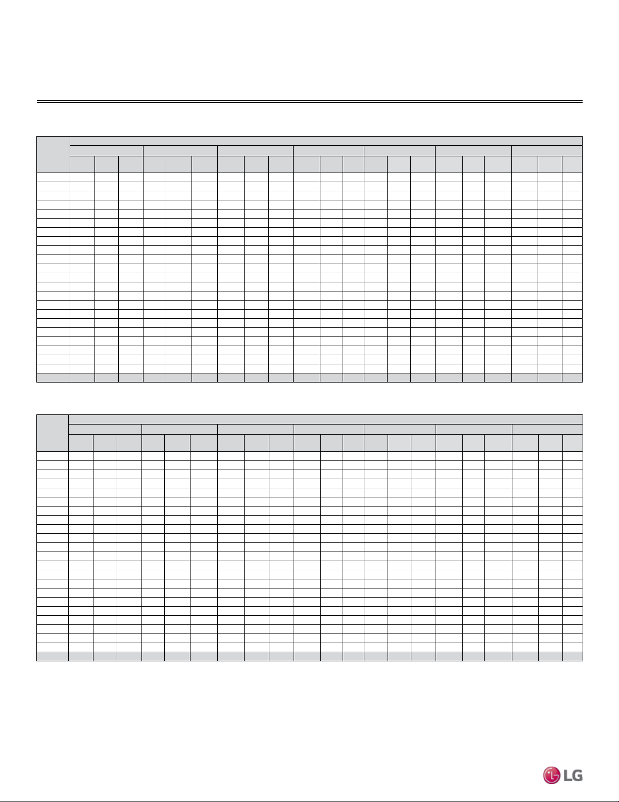
PERFORMANCE DATA
Cooling Capacity
Outdoor
Air
Temp.
(°F DB)
Indoor Air Temperature (°F DB/ °F WB)
64 / 53 68 / 57 72 / 61 77 / 64 80 / 67 86 / 72 90 / 75
TC SHC PI TC SHC PI TC SHC PI TC SHC PI TC SHC PI TC SHC PI TC SHC PI
14 7.35 5.66 0.49 7.90 6.08 0.50 8.45 6.50 0.52 9.00 6.93 0.53 9.25 7.12 0.55 10.10 7.77 0.57 10.65 8.20 0.59
23 7.89 6.07 0.48 8.48 6.53 0.50 9.07 6.98 0.51 9.66 7.44 0.53 9.93 7.65 0.55 10.84 8.35 0.57 11.43 8.80 0.58
25 8.00 6.16 0.49 8.59 6.61 0.51 9.18 7.07 0.52 9.77 7.52 0.54 10.04 7.73 0.56 10.95 8.43 0.58 11.54 8.89 0.59
30 8.31 6.40 0.53 8.92 6.86 0.55 9.52 7.33 0.56 10.10 7.78 0.58 10.38 7.99 0.60 11.30 8.70 0.62 11.93 9.18 0.64
35 8.62 6.64 0.57 9.24 7.12 0.58 9.86 7.59 0.60 10.43 8.03 0.62 10.72 8.25 0.64 11.64 8.96 0.66 12.31 9.48 0.68
40 8.93 6.88 0.60 9.57 7.37 0.62 10.20 7.85 0.64 10.75 8.28 0.66 11.05 8.51 0.68 11.98 9.23 0.71 12.70 9.78 0.73
45 9.24 7.12 0.64 9.89 7.62 0.66 10.54 8.12 0.68 11.08 8.53 0.70 11.39 8.77 0.72 12.32 9.49 0.75 13.08 10.07 0.77
50 9.56 7.36 0.67 10.22 7.87 0.70 10.88 8.38 0.72 11.41 8.79 0.74 11.73 9.03 0.76 12.67 9.75 0.79 13.46 10.37 0.82
55 9.87 7.60 0.71 10.54 8.12 0.73 11.22 8.64 0.76 11.74 9.04 0.78 12.07 9.29 0.80 13.01 10.02 0.83 13.85 10.66 0.86
60 10.18 7.84 0.75 10.87 8.37 0.77 11.56 8.90 0.79 12.06 9.29 0.82 12.40 9.55 0.84 13.35 10.28 0.88 14.23 10.96 0.90
65 10.49 8.08 0.78 11.19 8.62 0.81 11.90 9.16 0.83 12.39 9.54 0.86 12.74 9.81 0.89 13.70 10.55 0.92 14.62 11.25 0.95
70 10.80 8.32 0.82 11.52 8.87 0.85 12.24 9.42 0.87 12.72 9.79 0.90 13.08 10.07 0.93 14.04 10.81 0.96 15.00 11.55 0.99
75 10.66 8.21 0.84 11.38 8.77 0.87 12.11 9.32 0.90 12.60 9.70 0.92 12.96 9.98 0.95 13.86 10.67 0.99 14.88 11.46 1.02
80 10.38 7.99 0.88 11.10 8.55 0.91 11.82 9.10 0.94 12.36 9.52 0.96 12.84 9.89 0.99 13.68 10.53 1.03 14.64 11.27 1.07
85 10.11 7.78 0.94 10.83 8.34 0.97 11.54 8.89 1.00 12.12 9.33 1.03 12.60 9.70 1.06 13.50 10.40 1.11 14.42 11.10 1.14
90 9.83 7.57 0.98 10.55 8.12 1.01 11.26 8.67 1.04 11.88 9.15 1.08 12.36 9.52 1.11 13.32 10.26 1.15 14.13 10.88 1.19
95 9.53 7.34 1.01 10.25 7.89 1.04 10.96 8.44 1.08 11.67 8.99 1.11 12.00 9.24
1.14 13.10 10.09 1.19 13.81 10.64 1.22
100 9.28 7.15 1.03 10.00 7.70 1.06 10.71 8.25 1.09 11.42 8.80 1.13 11.84 9.12 1.16 12.85 9.89 1.21 13.56 10.44 1.24
105 9.03 6.95 1.05 9.75 7.50 1.08 10.46 8.05 1.11 11.17 8.60 1.15 11.69 9.00 1.18 12.60 9.70 1.23 13.31 10.25 1.27
110 8.78 6.76 1.06 9.50 7.31 1.09 10.21 7.86 1.12 10.92 8.41 1.16 11.44 8.81 1.19 12.35 9.51 1.24 13.07 10.06 1.28
115 8.53 6.57 1.07 9.25 7.12 1.10 9.96 7.67 1.13 10.67 8.22 1.17 11.19 8.62 1.21 12.10 9.32 1.25 12.82 9.87 1.29
118 8.28 6.38 1.08 9.00 6.93 1.11 9.60 7.39 1.15 10.32 7.95 1.18 10.80 8.32 1.22 11.70 9.01 1.27 12.36 9.52 1.30
122 7.89 6.07 1.08 8.56 6.59 1.12 9.24 7.11 1.15 9.91 7.63 1.19 10.40 8.01 1.22 11.27 8.67 1.27 11.94 9.19 1.31
Outdoor
Air
Temp.
(°F DB)
Indoor Air Temperature (°F DB/ °F WB)
64 / 53 68 / 57 72 / 61 77 / 64 80 / 67 86 / 72 90 / 75
TC SHC PI TC SHC PI TC SHC PI TC SHC PI TC SHC PI TC SHC PI TC SHC PI
14 5.20 4.58 0.30 5.59 4.92 0.31 5.98 5.26 0.32 6.37 5.61 0.33 6.55 5.77 0.34 7.15 6.29 0.35 7.54 6.64 0.36
23 5.59 4.92 0.30 6.00 5.28 0.31 6.42 5.65 0.32 6.84 6.02 0.33 7.03 6.19 0.34 7.68 6.76 0.35 8.10 7.13 0.36
25 5.67 4.99 0.31 6.08 5.35 0.31 6.50 5.72 0.32 6.92 6.09 0.33 7.11 6.26 0.34 7.76 6.83 0.36 8.18 7.19 0.37
30 5.89 5.18 0.33 6.31 5.56 0.34 6.74 5.93 0.35 7.15 6.29 0.36 7.35 6.47 0.37 8.00 7.04 0.38 8.45 7.43 0.40
35 6.11 5.37 0.35 6.55 5.76 0.36 6.98 6.15 0.37 7.39 6.50 0.38 7.59 6.68 0.40 8.24 7.25 0.41 8.72 7.67 0.42
40 6.33 5.57 0.37 6.78 5.96 0.38 7.23 6.36 0.40 7.62 6.70 0.41 7.83 6.89 0.42 8.49 7.47 0.44 8.99 7.91 0.45
45 6.55 5.76 0.40 7.01 6.17 0.41 7.47 6.57 0.42 7.85 6.91 0.43 8.07 7.10 0.45 8.73 7.68 0.46 9.26 8.15 0.48
50 6.77 5.96 0.42 7.24 6.37 0.43 7.71 6.78 0.44 8.08 7.11 0.46 8.31 7.31 0.47 8.97 7.90 0.49 9.54 8.39 0.51
55 6.99 6.15 0.44 7.47 6.57 0.45 7.95 6.99 0.47 8.31 7.32 0.48 8.55 7.52 0.50 9.22 8.11 0.52 9.81 8.63 0.53
60 7.21 6.34 0.46 7.70 6.77 0.48 8.19 7.21 0.49 8.55 7.52 0.51 8.79 7.73 0.52 9.46 8.32 0.54 10.08 8.87 0.56
65 7.43 6.54 0.49 7.93 6.98 0.50 8.43 7.42 0.52 8.78 7.72 0.53 9.03 7.94 0.55 9.70 8.54 0.57 10.35 9.11 0.59
70 7.65 6.73 0.51 8.16 7.18 0.52 8.67 7.63 0.54 9.01 7.93 0.56 9.27 8.15 0.57 9.95 8.75 0.60 10.63 9.35 0.61
75 7.55 6.65 0.52 8.06 7.10 0.54 8.58 7.55 0.56 8.93 7.85 0.57 9.18 8.08 0.59 9.82 8.64 0.61 10.54 9.28 0.63
80 7.35 6.47 0.55 7.86 6.92 0.56 8.38 7.37 0.58 8.76 7.70 0.60 9.10 8.00 0.62 9.69 8.53 0.64 10.37 9.13 0.66
85 7.16 6.30 0.58 7.67 6.75 0.60 8.18 7.20 0.62 8.59 7.55 0.64 8.93 7.85 0.66 9.56 8.42 0.68 10.21 8.99 0.71
90 6.96 6.13 0.61 7.47 6.57 0.63 7.98 7.02 0.65 8.42 7.41 0.67 8.76 7.70 0.69 9.44 8.30 0.71 10.01 8.81 0.74
95 6.75 5.94 0.63 7.26 6.39 0.65 7.76 6.83 0.67 8.27 7.28 0.69 8.50 7.48
0.71 9.28 8.17 0.74 9.78 8.61 0.76
100 6.57 5.79 0.64 7.08 6.23 0.66 7.59 6.68 0.68 8.09 7.12 0.70 8.39 7.38 0.72 9.10 8.01 0.75 9.61 8.46 0.77
105 6.40 5.63 0.65 6.90 6.08 0.67 7.41 6.52 0.69 7.91 6.96 0.71 8.28 7.29 0.73 8.93 7.85 0.76 9.43 8.30 0.78
110 6.22 5.47 0.65 6.73 5.92 0.68 7.23 6.36 0.70 7.74 6.81 0.72 8.10 7.13 0.74 8.75 7.70 0.77 9.25 8.14 0.79
115 6.04 5.32 0.66 6.55 5.76 0.68 7.06 6.21 0.70 7.56 6.65 0.72 7.93 6.98 0.75 8.57 7.54 0.78 9.08 7.99 0.80
118 5.87 5.16 0.67 6.38 5.61 0.69 6.80 5.98 0.71 7.31 6.43 0.73 7.65 6.73 0.75 8.29 7.29 0.78 8.76 7.70 0.81
122 5.59 4.92 0.67 6.07 5.34 0.69 6.54 5.76 0.71 7.02 6.18 0.73 7.37 6.48 0.76 7.98 7.02 0.79 8.46 7.44 0.81
Table 15: LSN090HXV/LSU090HXV Cooling Capacities.
Table 16: LSN120HXV/LSU120HXV Cooling Capacities.
DB: Dry Bulb Temperature (°F) WB: Wet Bulb Temperature (°F) TC: Total Capacity (kBtu/h)
SHC: Sensible Capacity (kBtu/h) PI: Power Input (kW) (includes compressor,indoor fan motor and
outdoor fan motor)
1. All capacities are net, evaporator fan motor heat is deducted.
2. Grey shading indicates reference data. When operating the unit at this temperature, these values
can be different by discontinuous operation.
3. Direct interpolation is permissible. Do not extrapolate.
Nominal capacity as rated: 0 ft. above sea level with 25 ft. of refrigerant piping.
0 ft. level difference between outdoor and indoor units.
Nominal cooling capacity rating obtained with air entering the indoor unit at 80ºF dry bulb (DB) and
67ºF wet bulb (WB), and outdoor ambient conditions of 95ºF dry bulb (DB) and 75ºF wet bulb (WB).
LS090HXV, LS120HXV
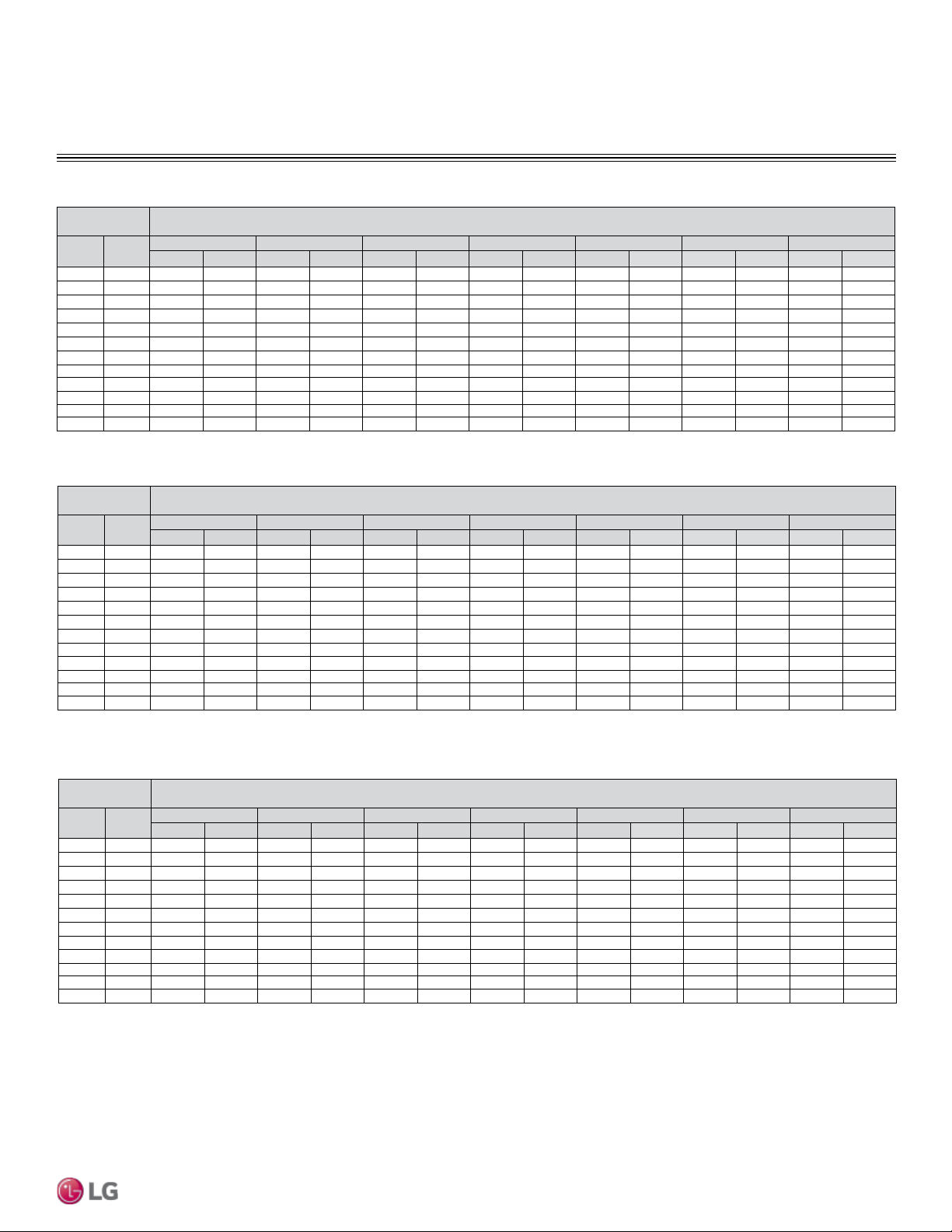
PRODUCT DATA | 43
Product Data
Due to our policy of continuous product innovation, some specications may change without notication.
©
LG Electronics U.S.A., Inc., Englewood Cliffs, NJ. All rights reserved. “LG ” is a registered trademark of LG Corp.
Heating Capacity
PERFORMANCE DATA
DB: Dry Bulb Temperature (°F) WB: Wet Bulb Temperature (°F) TC: Total Capacity (kBtu/h)
PI: Power Input (kW) (includes compressor,indoor fan motor and outdoor fan motor)
1. All capacities are net, evaporator fan motor heat is deducted.
2. Direct interpolation is permissible. Do not extrapolate.
Nominal capacity as rated: 0 ft. above sea level with 25 ft. of refrigerant piping.
0 ft. level difference between outdoor and indoor units.
Nominal heating capacity rating obtained with air entering the indoor unit at 70ºF dry bulb (DB) and
60ºF wet bulb (WB), and outdoor ambient conditions of 47ºF dry bulb (DB) and 43ºF wet bulb (WB).
Outdoor Air
Temp.
Indoor Air Temperature (°F DB)
°F DB °F WB
60 64 68 70 72 75 86
TC PI TC PI TC PI TC PI TC PI TC PI TC PI
16 14 5.70 0.62 5.52 0.62 5.47 0.62 5.41 0.61 5.37 0.61 5.26 0.60 5.14 0.60
19 17 5.81 0.64 5.64 0.64 5.58 0.64 5.52 0.63 5.48 0.63 5.37 0.62 5.24 0.62
24 23 6.37 0.67 6.18 0.66 6.12 0.66 6.06 0.65 6.01 0.65 5.89 0.65 5.75 0.65
32 30 7.64 0.72 7.41 0.71 7.33 0.71 7.26 0.70 7.21 0.70 7.06 0.70 6.89 0.70
41 38 8.77 0.77 8.50 0.76 8.41 0.76 8.33 0.75 8.27 0.75 8.10 0.74 7.91 0.74
43 40 9.05 0.78 8.77 0.77 8.68 0.77 8.60 0.76 8.53 0.76 8.36 0.75 8.16 0.75
47 43 9.47 0.80 9.18 0.79 9.09 0.79 9.00 0.78 8.93 0.78 8.75 0.77 8.54 0.77
53 50 9.57 0.80 9.27 0.80 9.18 0.80 9.09 0.79 9.02 0.79 8.84 0.78 8.63 0.78
59 53 9.78 0.81 9.49 0.80 9.39 0.80 9.30 0.80 9.23 0.80 9.04 0.79 8.83 0.79
64 57 9.99 0.83 9.69 0.82 9.59 0.82 9.50 0.81 9.42 0.81 9.23 0.80 9.01 0.80
70 61 10.18 0.84 9.87 0.83 9.77 0.83 9.68 0.82 9.60 0.82 9.41 0.81 9.18 0.81
75 65 10.32 0.85 10.01 0.84 9.91 0.84 9.81 0.83 9.74 0.83 9.54 0.83 9.31 0.83
Table 17: LSN090HEV1/LSU090HEV1 Heating Capacities.
Outdoor Air
Temp.
Indoor Air Temperature (°F DB)
°F DB °F WB
60 64 68 70 72 75 86
TC PI TC PI TC PI TC PI TC PI TC PI TC PI
16 14 7.59 0.78 7.36 0.77 7.29 0.77 7.22 0.77 7.16 0.77 7.02 0.76 6.85 0.76
19 17 7.75 0.81 7.51 0.80 7.44 0.80 7.36 0.79 7.31 0.79 7.16 0.78 6.99 0.78
24 23 8.50 0.84 8.24 0.83 8.16 0.83 8.08 0.82 8.02 0.82 7.85 0.81 7.67 0.81
32 30 10.19 0.90 9.88 0.89 9.78 0.89 9.68 0.89 9.61 0.89 9.41 0.88 9.19 0.88
41 38 11.69 0.96 11.33 0.95 11.22 0.95 11.11 0.94 11.02 0.94 10.80 0.93 10.55 0.93
43 40 12.06 0.98 11.70 0.97 11.58 0.97 11.47 0.96 11.38 0.96 11.15 0.95 10.88 0.95
47 43 12.63 1.00 12.24 0.99 12.12 0.99 12.00 0.98 11.91 0.98 11.67 0.97 11.39 0.97
53 50 12.75 1.01 12.37 1.00 12.24 1.00 12.12 0.99 12.03 0.99 11.79 0.98 11.51 0.98
59 53 13.04 1.02 12.65 1.01 12.52 1.01 12.40 1.00 12.30 1.00 12.05 0.99 11.77 0.99
64 57 13.32 1.04 12.92 1.03 12.79 1.03 12.66 1.02 12.56 1.02 12.31 1.01 12.02 1.01
70 61 13.57 1.05 13.16 1.04 13.03 1.04 12.90 1.03 12.80 1.03 12.54 1.02 12.25 1.02
75 65 13.76 1.07 13.35 1.06 13.21 1.06 13.08 1.05 12.98 1.05 12.72 1.04 12.42 1.04
Table 18: LSN120HEV1/LSU120HEV1 Heating Capacities.
Outdoor Air
Temp.
Indoor Air Temperature (°F DB)
°F DB °F WB
60 64 68 70 72 75 86
TC PI TC PI TC PI TC PI TC PI TC PI TC PI
16 14 12.02 12.69 11.66 12.57 11.54 12.57 11.43 12.44 11.34 12.44 11.11 12.32 10.85 12.32
19 17 12.27 13.08 11.90 12.96 11.78 12.96 11.66 12.83 11.57 12.83 11.34 12.70 11.07 12.70
24 23 13.46 13.57 13.05 13.43 12.92 13.43 12.79 13.30 12.69 13.30 12.44 13.17 12.14 13.17
32 30 16.13 14.65 15.64 14.51 15.48 14.51 15.33 14.36 15.21 14.36 14.91 14.22 14.55 14.22
41 38 18.51 15.62 17.95 15.46 17.76 15.46 17.59 15.31 17.45 15.31 17.10 15.16 16.70 15.16
43 40 19.10 15.86 18.52 15.70 18.33 15.70 18.15 15.55 18.01 15.55 17.65 15.39 17.23 15.39
47 43 19.99 16.22 19.39 16.06 19.19 16.06 19.00 15.90 18.85 15.90 18.48 15.74 18.04 15.74
53 50 20.19 16.38 19.58 16.22 19.38 16.22 19.19 16.06 19.04 16.06 18.66 15.90 18.22 15.90
59 53 20.65 16.54 20.03 16.38 19.82 16.38 19.63 16.22 19.48 16.22 19.09 16.06 18.63 16.06
64 57 21.09 16.87 20.45 16.70 20.25 16.70 20.05 16.54 19.89 16.54 19.49 16.37 19.03 16.37
70 61 21.49 17.11 20.84 16.94 20.63 16.94 20.43 16.77 20.27 16.77 19.86 16.61 19.39 16.61
75 65 21.79 17.35 21.13 17.18 20.92 17.18 20.71 17.01 20.55 17.01 20.14 16.84 19.66 16.84
Table 19: LSN180HEV1/LSU180HEV1 Heating Capacities.
LS090HEV1, LS120HEV1, LS180HEV1
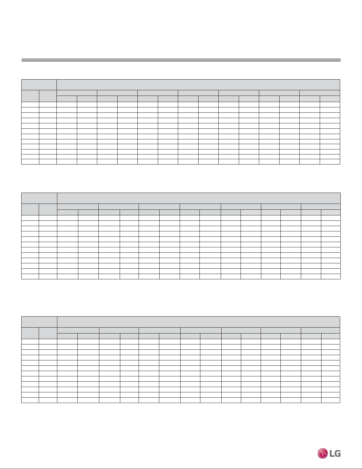
44 | PRODUCT DATA
Single Zone Mega Wall Mounted Engineering Manual
Due to our policy of continuous product innovation, some specications may change without notication.
©
LG Electronics U.S.A., Inc., Englewood Cliffs, NJ. All rights reserved. “LG ” is a registered trademark of LG Corp.
Heating Capacity
PERFORMANCE DATA
Outdoor Air
Temp.
Indoor Air Temperature (°F DB)
°F DB °F WB
60 64 68 70 72 75 86
TC PI TC PI TC PI TC PI TC PI TC PI TC PI
16 14 6.90 0.70 6.69 0.70 6.62 0.70 6.55 0.69 6.50 0.69 6.37 0.68 6.22 0.68
19 17 7.04 0.72 6.82 0.72 6.76 0.72 6.69 0.71 6.64 0.71 6.50 0.70 6.35 0.70
24 23 7.72 0.75 7.49 0.74 7.41 0.74 7.34 0.74 7.28 0.74 7.13 0.73 6.96 0.73
32 30 9.25 0.81 8.97 0.80 8.88 0.80 8.79 0.80 8.73 0.80 8.55 0.79 8.35 0.79
41 38 10.62 0.86 10.30 0.86 10.19 0.86 10.09 0.85 10.01 0.85 9.81 0.84 9.58 0.84
43 40 10.96 0.88 10.63 0.87 10.52 0.87 10.41 0.86 10.33 0.86 10.13 0.85 9.89 0.85
47 43 11.47 0.90 11.12 0.89 11.01 0.89 10.90 0.88 10.82 0.88 10.60 0.87 10.35 0.87
53 50 11.58 0.91 11.23 0.90 11.12 0.90 11.01 0.89 10.92 0.89 10.71 0.88 10.45 0.88
59 53 11.85 0.92 11.49 0.91 11.37 0.91 11.26 0.90 11.17 0.90 10.95 0.89 10.69 0.89
64 57 12.10 0.93 11.73 0.92 11.61 0.92 11.50 0.92 11.41 0.92 11.18 0.91 10.92 0.91
70 61 12.33 0.95 11.96 0.94 11.83 0.94 11.72 0.93 11.63 0.93 11.39 0.92 11.12 0.92
75 65 12.50 0.96 12.12 0.95 12.00 0.95 11.88 0.94 11.79 0.94 11.55 0.93 11.28 0.93
Outdoor Air
Temp.
Indoor Air Temperature (°F DB)
°F DB °F WB
60 64 68 70 72 75 86
TC PI TC PI TC PI TC PI TC PI TC PI TC PI
16 14 8.23 0.87 7.98 0.86 7.90 0.86 7.82 0.85 7.76 0.85 7.60 0.84 7.42 0.84
19 17 8.39 0.90 8.14 0.89 8.06 0.89 7.98 0.88 7.92 0.88 7.76 0.87 7.57 0.87
24 23 9.21 0.93 8.93 0.92 8.84 0.92 8.75 0.91 8.68 0.91 8.51 0.90 8.31 0.90
32 30 11.04 1.00 10.70 0.99 10.59 0.99 10.49 0.98 10.41 0.98 10.20 0.97 9.96 0.97
41 38 12.66 1.07 12.28 1.06 12.15 1.06 12.03 1.05 11.94 1.05 11.70 1.04 11.42 1.04
43 40 13.07 1.09 12.67 1.07 12.54 1.07 12.42 1.06 12.33 1.06 12.08 1.05 11.79 1.05
47 43 13.68 1.11 13.26 1.10 13.13 1.10 13.00 1.09 12.90 1.09 12.64 1.08 12.34 1.08
53 50 13.82 1.12 13.40 1.11 13.26 1.11 13.13 1.10 13.03 1.10 12.77 1.09 12.46 1.09
59 53 14.13 1.13 13.70 1.12 13.56 1.12 13.43 1.11 13.33 1.11 13.06 1.10 12.75 1.10
64 57 14.43 1.15 13.99 1.14 13.85 1.14 13.72 1.13 13.61 1.13 13.34 1.12 13.02 1.12
70 61 14.71 1.17 14.26 1.16 14.11 1.16 13.98 1.15 13.87 1.15 13.59 1.14 13.27 1.14
75 65 14.91 1.19 14.46 1.18 14.31 1.18 14.17 1.16 14.06 1.16 13.78 1.15 13.45 1.15
LS240HEV1, LS090HXV, LS120HXV
Outdoor Air
Temp.
Indoor Air Temperature (°F DB)
°F DB °F WB
60 64 68 70 72 75 86
TC PI TC PI TC PI TC PI TC PI TC PI TC PI
16 14 13.92 15.45 13.50 15.30 13.36 15.30 13.23 15.14 13.13 15.14 12.87 14.99 12.56 14.99
19 17 14.21 15.92 13.77 15.77 13.64 15.77 13.50 15.61 13.40 15.61 13.13 15.46 12.82 15.46
24 23 15.58 16.51 15.11 16.35 14.96 16.35 14.81 16.19 14.69 16.19 14.40 16.03 14.06 16.03
32 30 18.68 17.83 18.11 17.66 17.93 17.66 17.75 17.48 17.61 17.48 17.26 17.31 16.85 17.31
41 38 21.43 19.00 20.78 18.82 20.57 18.82 20.37 18.63 20.21 18.63 19.80 18.44 19.33 18.44
43 40 22.12 19.30 21.45 19.11 21.23 19.11 21.02 18.92 20.86 18.92 20.44 18.73 19.95 18.73
47 43 23.15 19.74 22.45 19.54 22.22 19.54 22.00 19.35 21.83 19.35 21.39 19.16 20.88 19.16
53 50 23.38 19.93 22.67 19.74 22.44 19.74 22.22 19.54 22.05 19.54 21.61 19.35 21.09 19.35
59 53 23.91 20.13 23.19 19.93 22.95 19.93 22.73 19.74 22.55 19.74 22.10 19.54 21.57 19.54
64 57 24.42 20.53 23.68 20.33 23.44 20.33 23.21 20.12 23.03 20.12 22.57 19.92 22.03 19.92
70 61 24.89 20.82 24.13 20.62 23.89 20.62 23.65 20.41 23.47 20.41 23.00 20.21 22.45 20.21
75 65 25.23 21.12 24.47 20.91 24.22 20.91 23.98 20.70 23.80 20.70 23.32 20.50 22.76 20.50
Table 20: LSN240HEV1/LSU240HEV1 Heating Capacities.
DB: Dry Bulb Temperature (°F) WB: Wet Bulb Temperature (°F) TC: Total Capacity (kBtu/h)
PI: Power Input (kW) (includes compressor,indoor fan motor and outdoor fan motor)
1. All capacities are net, evaporator fan motor heat is deducted.
2. Direct interpolation is permissible. Do not extrapolate.
Nominal capacity as rated: 0 ft. above sea level with 25 ft. of refrigerant piping.
0 ft. level difference between outdoor and indoor units.
Nominal heating capacity rating obtained with air entering the indoor unit at 70ºF dry bulb (DB) and
60ºF wet bulb (WB), and outdoor ambient conditions of 47ºF dry bulb (DB) and 43ºF wet bulb (WB).
Table 21: LSN090HXV/LSU090HXV Heating Capacities.
Table 22: LSN120HXV/LSU120HXV Heating Capacities.
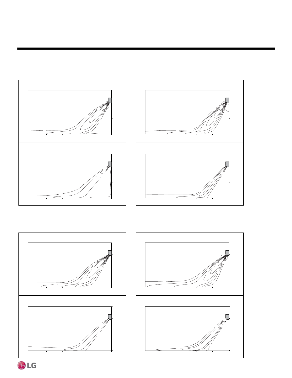
PRODUCT DATA | 45
Product Data
Due to our policy of continuous product innovation, some specications may change without notication.
©
LG Electronics U.S.A., Inc., Englewood Cliffs, NJ. All rights reserved. “LG ” is a registered trademark of LG Corp.
PERFORMANCE DATA
Air Flow and Temperature Distributions Graphs
LSN090HEV1
LSN120HEV1
Cooling
Discharge angle:45°
Heating
Discharge angle:50°
Coolin
g
Discharge angle:45°
Heating
Discharge angle:50°
Air velocity [ft/s]
Temperature [°F]
1.6
1.6
3.3
4.9
4.9
6.6
3.3
1.6
8.2
0
3.3
6.6
[ ft ]
03.36.69.813.116.4
[ ft ]
78.8
78.8
82.4
86
0
3.3
6.6
[ ft ]
03.36.69.813.116.4
[ ft ]
Air velocity [ft/s]
Temperature [°F]
1.6
3.3
6.6
4.9
1.6
3.3
8.2
4.9
9.8
0
3.3
6.6
[ ft ]
03.36.69.813.116.4
[ ft ]
69.8
69.8
69.8
66.2
73.4
0
3.3
6.6
[ ft ]
03.36.69.813.116.4
[ ft ]
Air velocity [ft/s]
Temperature [°F]
1.6
3.3
3.3
9.8
6.6
4.9
4.9
8.2
11
.5
0
3.3
6.6
[ ft ]
03.36.69.813.116.4
[ ft ]
78.8
78.8
78.8
82.4
82.4
89.6
86
82.4
86
86
0
3.3
6.6
[ ft ]
03.36.69.813.116.4
[ ft ]
Air velocity [ft/s]
Temperature [°F]
0
3.3
6.6
[ ft ]
03.36.69.813.116.4
[ ft ]
3.3
1.6
4.9
4.9
3.3
8.2
3.3
1.6
6.6
0
3.3
6.6
[ ft ]
03.36.69.813.116.4
[ ft ]
69.8
69.8
69.8
66.2
66.2
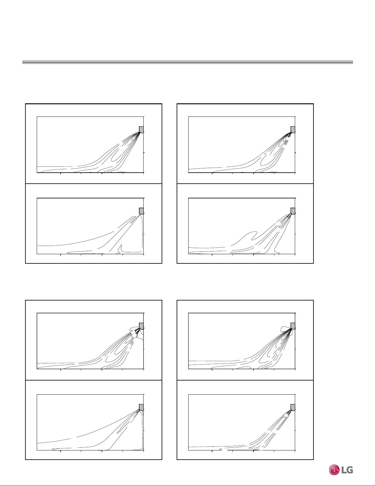
46 | PRODUCT DATA
Single Zone Mega Wall Mounted Engineering Manual
Due to our policy of continuous product innovation, some specications may change without notication.
©
LG Electronics U.S.A., Inc., Englewood Cliffs, NJ. All rights reserved. “LG ” is a registered trademark of LG Corp.
PERFORMANCE DATA
Air Flow and Temperature Distributions Graphs
LSN180HEV1
LSN240HEV1
Cooling
Discharge angle:45°
Heating
Discharge angle:50°
80. 6
87. 8
87.8
84. 2
84.2
84. 2
3.3
4.9
4.9
6.6
6.6
8.2
Air velocity [ft/s]
Temperature [°F]
0
3.3
6.6
[ ft ]
03.36.69.813.116.4
[ ft ]
0
3.3
6.6
[ ft ]
03.36.69.813.116.4
[ ft ]
66.2
66.2
66.2
69.8
69.8
Air velocity [ft/s]
Temperature [°F]
0
3.3
6.6
[ ft ]
03.36.69.813.116.4
[ ft ]
8.2
4.9
4.9
1.6
3.3
6.6
3.3
0
3.3
6.6
[ ft ]
03.36.69.813.116.4
[ ft ]
Coolin
g
Discharge angle:45°
Heating
Discharge angle:50°
84. 2
91.4
87.8
87.8
95
4.9
1.6
3.3
3.3
6.6
8.2
9.8
1.6
4.9
Air velocity [ft/s]
Temperature [°F]
0
3.3
6.6
[ ft ]
03.36.69.813.116.4
[ ft ]
0
3.3
6.6
[ ft ]
03.36.69.813.116.4
[ ft ]
87. 8
84. 2
66.2
66.2
62.6
3.3
4.9
6.6
3.3
4.9
1.6
9.8
8.2
Air velocity [ft/s]
Temperature [°F]
0
3.3
6.6
[ ft ]
03.36.69.813.116.4
[ ft ]
0
3.3
6.6
[ ft ]
03.36.69.813.116.4
[ ft ]
69.8
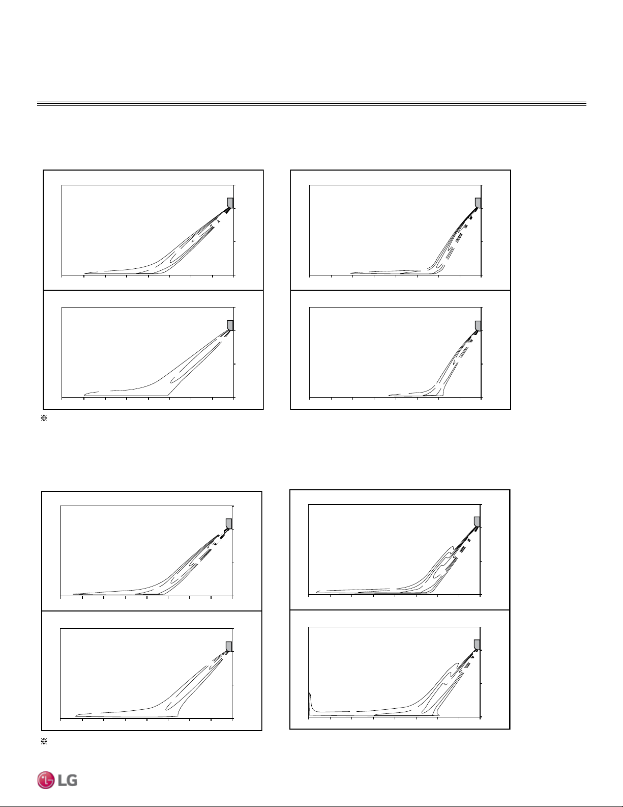
PRODUCT DATA | 47
Product Data
Due to our policy of continuous product innovation, some specications may change without notication.
©
LG Electronics U.S.A., Inc., Englewood Cliffs, NJ. All rights reserved. “LG ” is a registered trademark of LG Corp.
PERFORMANCE DATA
Air Flow and Temperature Distributions Graphs
LSN090HXV
LSN120HXV
Cooling
Discharge angle: 45°
Heating
Discharge angle: 50°
Air velocity [ft/s]
Temperature [°F]
6.6ft
3.3ft
0ft
26.2ft 13.1ft 9.8ft 6.6ft 3.3ft
0ft
16.4ft19.7ft23.0ft
6.6ft
3.3ft
0ft
26.2ft 13.1ft 9.8ft 6.6ft 3.3ft
0ft
16.4ft19.7ft23.0ft
3. 3
73.4
69.8
66.2
11
.5
9.8
8.2
4.9
6.6
Air velocity [ft/s]
Temperature [°F]
3. 3
98. 6
91. 4
87. 8
84.2
80. 6
11 .5
13.1
9.8
8.2
4.9
6.6
6.6ft
3.3ft
0ft
26.2ft 13.1ft 9.8ft 6.6ft 3.3ft
0ft
16.4ft19.7ft23.0ft
6.6ft
3.3ft
0ft
26.2ft 13.1ft 9.8ft 6.6ft 3.3ft
0ft
16.4ft19.7ft23.0ft
Air velocity [ft/s]
Temperature [°F]
64. 4
66. 2
69. 8
73. 4
8.2
13.1
11
.5
9.8
8.2
6.6
4.9
3. 3
6.6ft
3.3ft
0ft
26.2ft 13.1ft 9.8ft 6.6ft 3.3ft
0ft
16.4ft19.7ft23.0ft
6.6ft
3.3ft
0ft
26.2ft 13.1ft 9.8ft 6.6ft 3.3ft
0ft
16.4ft19.7ft23.0ft
Air velocity [ft/s]
Temperature [°F]
3. 3
4. 9
86
93. 2
89. 6
86
82. 4
78. 8
11
.5
13.1
9.8
8.2
6.6
6.6ft
3.3ft
0ft
26.2ft 13.1ft 9.8ft 6.6ft 3.3ft
0ft
16.4ft19.7ft23.0ft
6.6ft
3.3ft
0ft
26.2ft 13.1ft 9.8ft 6.6ft 3.3ft
0ft
16.4ft19.7ft23.0ft
Cooling
Discharge angle:45°
Heating
Discharge angle:50°
Based on maximum air flow.
Based on maximum air flow.

48 | PRODUCT DATA
Single Zone Mega Wall Mounted Engineering Manual
Due to our policy of continuous product innovation, some specications may change without notication.
©
LG Electronics U.S.A., Inc., Englewood Cliffs, NJ. All rights reserved. “LG ” is a registered trademark of LG Corp.

“Equipment Selection Procedure” on page 50
“Building Ventilation Design Guide” on page 52
“Placement Considerations” on page 54
APPLICATION
GUIDELINES
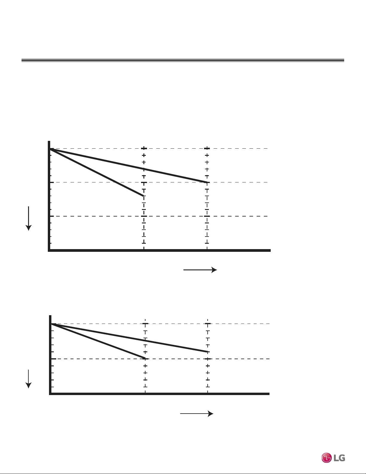
50 | APPLICATION GUIDELINES
Single Zone Mega Wall Mounted Engineering Manual
Due to our policy of continuous product innovation, some specications may change without notication.
©
LG Electronics U.S.A., Inc., Englewood Cliffs, NJ. All rights reserved. “LG ” is a registered trademark of LG Corp.
EQUIPMENT SELECTION PROCEDURE
Cooling / Heating Correction Factors
For the Single Zone Mega Wall Mounted system, calculate the equivalent length of the liquid line from the outdoor unit to the indoor unit.
Also, determine the elevation difference of the indoor unit above or below the outdoor unit. Find corresponding cooling or heating capacity
correction factors as shown in Figures 17 through 20. Multiply the correction factors by the cooling or heating capacity obtained from the
capacity tables using design conditions. The resultant is the NET cooling or heating capacity.
Figure 17: LS090-240HEV1 Cooling Coefcient Factor.
Figure 18: LS090-240HEV1 Heating Coefcient Factor.
Cooling
9k,12k
18k,24k
49.2 65.6
To tal Pipe Length (ft)
100
24.6
90
Capacity(%)
Heating
24.6
100
95
9k,12k
18k,24k
49.2 65.6
To tal Pipe Length (ft)
Capacity(%)
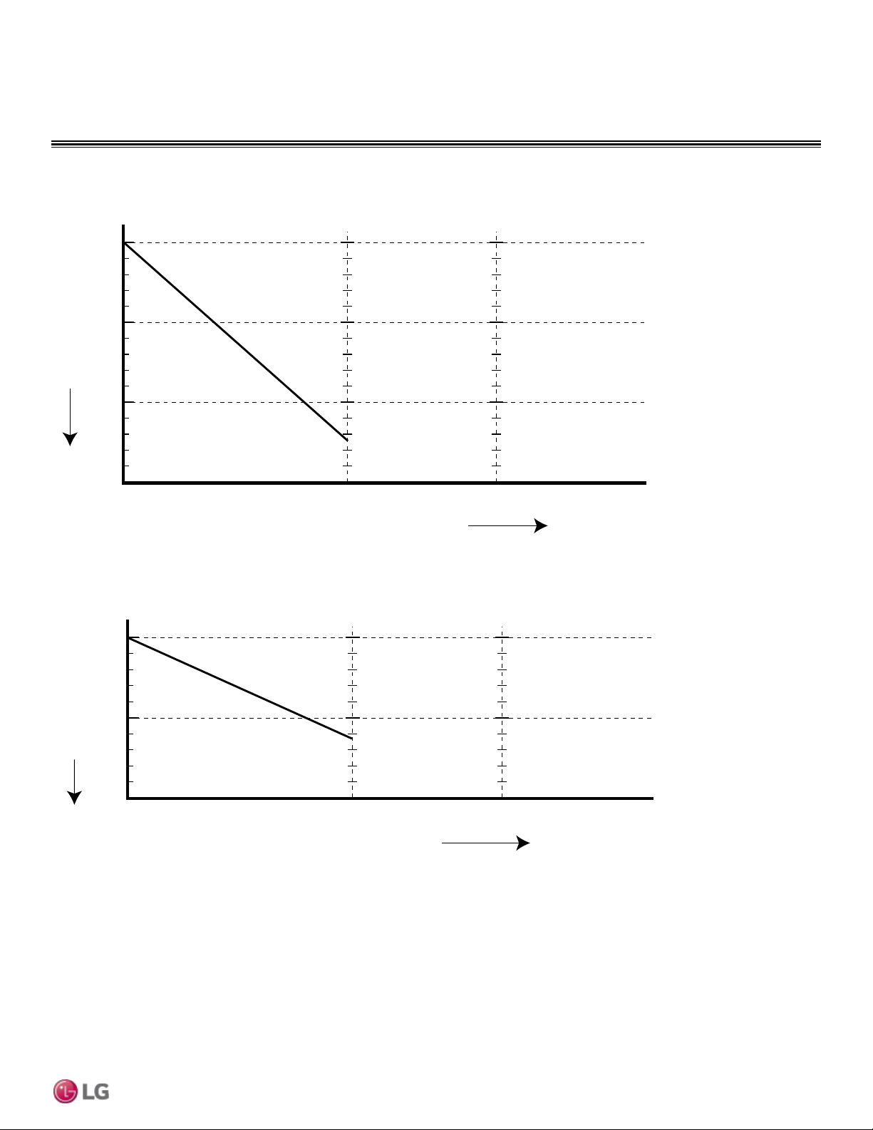
APPLICATION GUIDELINES | 51
Application Guidelines
Due to our policy of continuous product innovation, some specications may change without notication.
©
LG Electronics U.S.A., Inc., Englewood Cliffs, NJ. All rights reserved. “LG ” is a registered trademark of LG Corp.
Figure 19: LS090HXV, LS120HXV Cooling Coefcient Factor.
Figure 20: LS090HXV, LS120HXV Heating Coefcient Factor.
EQUIPMENT SELECTION PROCEDURE
Cooling
9k,12k
49.2 98.4
T
otal Pipe Length (ft)
Capacity (%)
100
90
95
24.6
Heating
Capacity (%)
24.6
100
95
9k,12k
49.2 98.4
Total Pipe Length (ft)
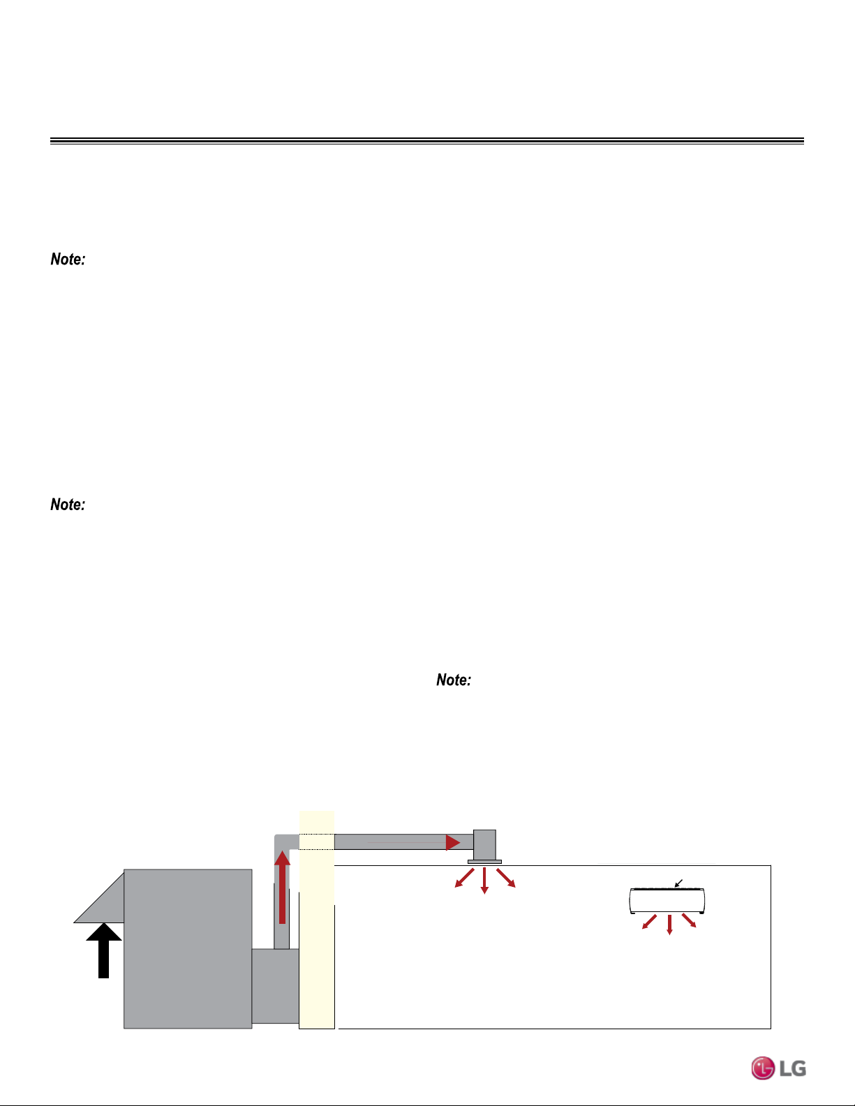
52 | APPLICATION GUIDELINES
Single Zone Mega Wall Mounted Engineering Manual
Due to our policy of continuous product innovation, some specications may change without notication.
©
LG Electronics U.S.A., Inc., Englewood Cliffs, NJ. All rights reserved. “LG ” is a registered trademark of LG Corp.
BUILDING VENTILATION DESIGN GUIDE
Advantages
• May be used with all single zone systems.
• The outdoor air unit may supply “neutral” air to the occupant space
even when the single zone indoor unit fan changes speed or cycles
on and off. DDOAS controls do not have to be interlocked with the
single zone system.
• In lieu of installing localized smaller outside air treatment
equipment throughout the building, this method centralizes the
ventilation air source making service and filter changes easier and
less disruptive for the building occupants.
• Third-party demand control ventilation controls are more readily
accommodated.
Disadvantages
• Ceiling space is required to accommodate ductwork between the
centralized outdoor air unit and ceiling diffusers.
LG recommends using the DDOAS method in all installations.
Ceiling Diffuser
Outdoor Air Unit / ERV
Outdoor Air
Wall Mount Inverter
Intake Grill
Figure 21: Decoupled Dedicated Outdoor System Diagram
Methodology illustrations are for examples only and do not depict actual
indoor units for the specic outdoor unit pairing. These are generic illus-
trations to show ventilation design only.
Building Ventilation Design Guide
ASHRAE 62.1 and local codes specify the minimum volume of outdoor air that must be provided to an occupied space. Outdoor air is
required to minimize adverse health effects, and it provides acceptable indoor air quality for building occupants. The three methods of ac-
complishing this with single zone systems are summarized here.
Method 1: Decoupled Dedicated Outdoor Air System (DDOAS)
Provide a separate, dedicated outdoor-air system designed to filter, condition, and dehumidify ventilation air and deliver it directly to the
conditioned space through a separate register or grille. This approach requires a separate independent ventilation duct system not associ-
ated with single zone systems (Figure 21).
Although we believe that these building ventilation methods have been portrayed accurately, none of the methods have been tested, veried, or
evaluated by LG Electronics, U.S.A., Inc., In all cases, the designer, installer, and contractor should understand if the suggested method is used, it
is used at their own risk. LG Electronics U.S.A., Inc., takes no responsibility and offers no warranty, expressed or implied, in law or in fact, including
but not limited to any implied warranty of merchantability or tness for a particular purpose.
• For a complete copy of Standard 62.1-2010, refer to the American Standard of Heating and Air Conditioning Engineers (ASHRAE)
website at www.ashrae.org.
• For more information on how to properly size a ventilation air pretreatment system, refer to the article, “Selecting DOAS Equipment with
Reserve Capacity” by John Murphy, published in the ASHRAE Journal, April 2010.
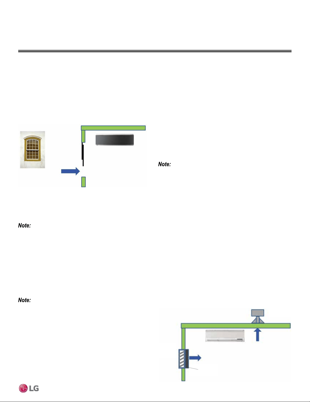
APPLICATION GUIDELINES | 53
Application Guidelines
Due to our policy of continuous product innovation, some specications may change without notication.
©
LG Electronics U.S.A., Inc., Englewood Cliffs, NJ. All rights reserved. “LG ” is a registered trademark of LG Corp.
BUILDING VENTILATION DESIGN GUIDE
Method 2: Unconditioned Outdoor Air (Non-Ducted, Natural Ventilation)
Natural ventilation devices, such as operable windows or louvers may be used to ventilate the building when local code permits. The open
area of a window or the free area of a louver must meet the minimum percentage of the net occupied floor area. Refer to Figure 22.
Advantages
• Occupants control the volume of the ventilation air manually.
• Useful for historic buildings that have no ceiling space available for
outdoor air ductwork.
• May be used with single zone systems.
Disadvantages
• In some locations, it may be difficult to control humidity levels when
windows are open.
• Thermal comfort levels may be substandard when windows are open.
• Indoor units may have to be oversized to account for the added
heating and cooling loads when windows are open.
• Provides outdoor air to perimeter spaces only. Additional mechani-
cal ventilation system may be required to satisfy requirements for
interior spaces.
• Outdoor air loads may be difficult to calculate since the quantity of
outdoor air is not regulated.
• May affect indoor unit proper operation when open.
Method 3: Unconditioned Outdoor Air (Non-Ducted, Fan Assisted Ventilation)
When approved by local codes, the fan assisted ventilation method uses exhaust fans to remove air from the building, and outdoor air is
drawn into occupied spaces through a wall louver or gravity roof intake hood. Supply fans can also be used to push the outdoor air into the
space and building positive pressure will vent the exhaust air through louvers or roof-mounted exhaust hoods. Outdoor air is neither cooled
nor heated before entering the building. Refer to Figure 23.
Advantages
• Outdoor air may be manually controlled by the occupant or auto-
matic controls may be installed to open/close outdoor air dampers
or to turn on/off ventilation fans.
• Useful for large open spaces like warehouses, garages, and
workshops.
• Outdoor air volume is a known quantity. Air loads may be easier to
calculate since fans will regulate the amount of outdoor air.
• May be used with single zone systems.
Disadvantages
• In some locations of the country, it may be difficult to control
humidity levels while outdoor air louvers/hoods are opened.
• Thermal comfort levels may be substandard when louvers/hoods
are opened.
• Indoor units may have to be oversized to account for the added
heating/cooling loads when louvers/hoods are open.
• Hot, cold, and/or humid areas may be present if the outdoor air is
not evenly distributed to the different spaces.
This may result in loss of building pressurization control, increasing inltration loads with adverse effects.
Figure 22: Unconditioned Outdoor Air (Non-Ducted)
OA Wall
Louver
Damper
Roof Fan
Figure 23: Unconditioned Outdoor Air (Non-Ducted)
Methodology illustrations are for examples only and do not depict actual
indoor units for the specic outdoor unit pairing. These are generic illus-
trations to show ventilation design only.
Methodology illustrations are for examples only and do not depict
actual indoor units for the specic outdoor unit pairing. These are
generic illustrations to show ventilation design only.
54 | APPLICATION GUIDELINES
Single Zone Mega Wall Mounted Engineering Manual
Due to our policy of continuous product innovation, some specications may change without notication.
©
LG Electronics U.S.A., Inc., Englewood Cliffs, NJ. All rights reserved. “LG ” is a registered trademark of LG Corp.
PLACEMENT CONSIDERATIONS
Selecting the Best Location
DANGER
To avoid the possibility of re, do not install the unit in an area where combustible gas may generate, ow, stagnate, or leak. Failure to do so will cause
serious bodily injury or death.
• Install a fence to prevent vermin from crawling into the unit or unauthorized individuals from accessing it.
• Do not install the unit in a location where acidic solution and spray (sulfur) are often used as this may cause serious bodily injury or death.
• Do not use the unit in environments where oil, steam, or sulfuric gas are present as this may cause serious bodily injury or death.
Select a location for installing the outdoor unit that will meet the following conditions:
• Where the unit will not be subjected to direct thermal radiation from other heat sources.
• Where operating sound from the unit will not disturb inhabitants of surrounding buildings.
• Where the unit will not be exposed to direct, strong winds.
• Where there is enough strength to bear the weight of the unit.
• Include space for drainage to ensure condensate flows properly out of the unit when it is in heating mode.
• Include enough space for air flow and for service access.
To ensure the outdoor unit operates properly, certain measures are required in locations where there is a possibility of heavy snowfall or
severe wind chill or cold:
1. Prepare for severe winter wind chills and heavy snowfall, even in areas of the country where these are unusual phenomena.
2. Position the outdoor unit so that its airflow fans are not buried by direct, heavy snowfall. If snow piles up and blocks the airflow, the
system may malfunction.
3. Remove any snow that has accumulated by 4 inches or more on the top of the outdoor unit.
4. Place the outdoor unit on a raised platform at least 20 inches higher than the average annual snowfall for the area. In environments where
there is a possibility of heavy snow, the frame height must be more than two (2) times the amount of average annual snowfall, and should
not exceed the width of the outdoor unit. If the frame width is wider than the outdoor unit, snow may accumulate.
5. Install a snow protection hood.
6. To prevent snow and heavy rain from entering the outdoor unit, install the suction and discharge ducts facing away from direct winds.
7. Additionally, the following conditions should be taken into consideration when the unit operates in defrost mode:
• If the outdoor unit is installed in a highly humid environment (near an ocean, lake, etc.), ensure that the site is well-ventilated and has a lot
of natural light. (Example: Install on a rooftop.)
• Sidewalks or parking lots near the outdoor unit may accumulate moisture after unit operates in defrost mode that can turn to ice.
The indoor unit may take longer to provide heat, or heating performance will be reduced in winter if the unit is installed:
1. In a narrow, shady location.
2. Near a location that has a lot of ground moisture.
3. In a highly humid environment.
4. In an area in which condensate does not drain properly.
Ambient Air Conditions
• Avoid exposing the unit to discharge from boiler stacks, chimneys, steam relief ports, other air conditioning units, kitchen vents, plumbing
vents, or substances that may degrade performance or cause damage to the unit.
• When installing multiple outdoor units, avoid placing the units where discharge of one outdoor unit will blow into the inlet side of an
adjacent unit.
Avoid exposing the unit to sources of extreme temperature or gases to prevent serious bodily injury.
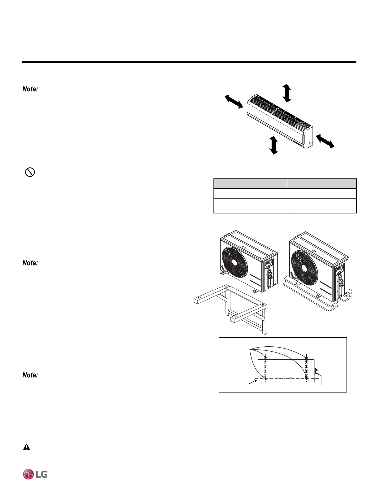
APPLICATION GUIDELINES | 55
Application Guidelines
Due to our policy of continuous product innovation, some specications may change without notication.
©
LG Electronics U.S.A., Inc., Englewood Cliffs, NJ. All rights reserved. “LG ” is a registered trademark of LG Corp.
PLACEMENT CONSIDERATIONS
Indoor Unit Clearance/Outdoor Unit Installation
General Mounting for Outdoor Units
Securely attach the outdoor unit to a condenser pad, base rails, or
another mounting platform that is securely anchored to the ground
or building structure. Attach the outdoor unit with a bolt and nut on
a concrete or rigid mount. See Figure 25. Refer to the applicable
installation manual and follow applicable local codes for clearance,
mounting, anchor and vibration attenuation requirements.
All referenced materials are to be eld-supplied. Images are not
to scale.
Mounting Platform
The underlying structure or foundation must be designed to support
the weight of the unit. Avoid placing the unit in a low lying area
where water may accumulate. When installing the outdoor unit on
the wall, or roof top, anchor the mounting base securely to account
for wind, earthquake or vibration.
Tie-Downs and Wind Restraints
The strength of the Duct-free Split Single Zone Inverter system
frame is adequate to be used with field-provided wind restraint
tie-downs. The overall tie-down configuration must be approved by a
local professional engineer.
Always refer to local code when designing a wind restraint system.
Snow and Ice Conditions
In climates that experience snow build-up, place the unit on a raised platform to ensure condenser airflow. The raised support platform must
be high enough to allow the unit to remain above possible snow drifts. Mount the unit on a field-provided snow stand at a minimum height
that is equal to the average annual snowfall plus 20 inches. Design the mounting base to prevent snow accumulation on the platform in front
or back of the unit case. If necessary, provide a field fabricated hood to keep snow and ice and/or drifting snow from accumulating on the coil
surfaces. Use inlet and discharge duct or hoods to prevent snow or rain from accumulating on the fan inlet and outlet guards. Best practice
prevents snow from accumulating on top of the unit. Consider tie-down requirements in case of high winds or where required by local codes.
Figure 24: Single Zone Indoor Unit Clearance Requirements.
Bolt
Placement
& Anti-Vibration
Pad
Piping Connection
Top of Unit
Foundation
Indoor Unit Best Location
Follow recommended best practices when choosing an indoor location for the
single zone indoor unit.
• Use a metal detector to locate studs in the walls. Anchor unit following stud
location, to prevent damage to the wall.
• Clearance gap between any wall or enclosure and the left or right side of the
unit must be greater than 4 inches (Figure 24).
• Follow Table 11 for minimum clearance of indoor unit from the top of the unit
to the ceiling.
• Unit should be at least 6.5 feet from the oor for adequate clearance.
Minimum clearance
from ceiling - “A”
More than 4 inches
More than
4 inches
At least 6.5 feet from the floor
“A” Ceiling Clearance (inches) Indoor Unit Model(s)
5 LSN090HEV1, LSN120HEV1
8
LSN090HXV, LSN120HXV,
LSN180HEV1, LSN240HEV1
Table 11: Indoor Unit Ceiling Clearance.
Figure 25: Outdoor Unit Mounting Methods.
When deciding on a location to place the outdoor unit, be sure to choose an area where run-off from defrost will not accumulate and freeze on
sidewalks or driveways which may create unsafe conditions.
CAUTION
• Keep unit away from any indoor steam or excessive heat.
• No obstacles should be placed around unit.
• Condensation drain (leakage piping) should be routed away from the unit.
• Do not install near doorway.
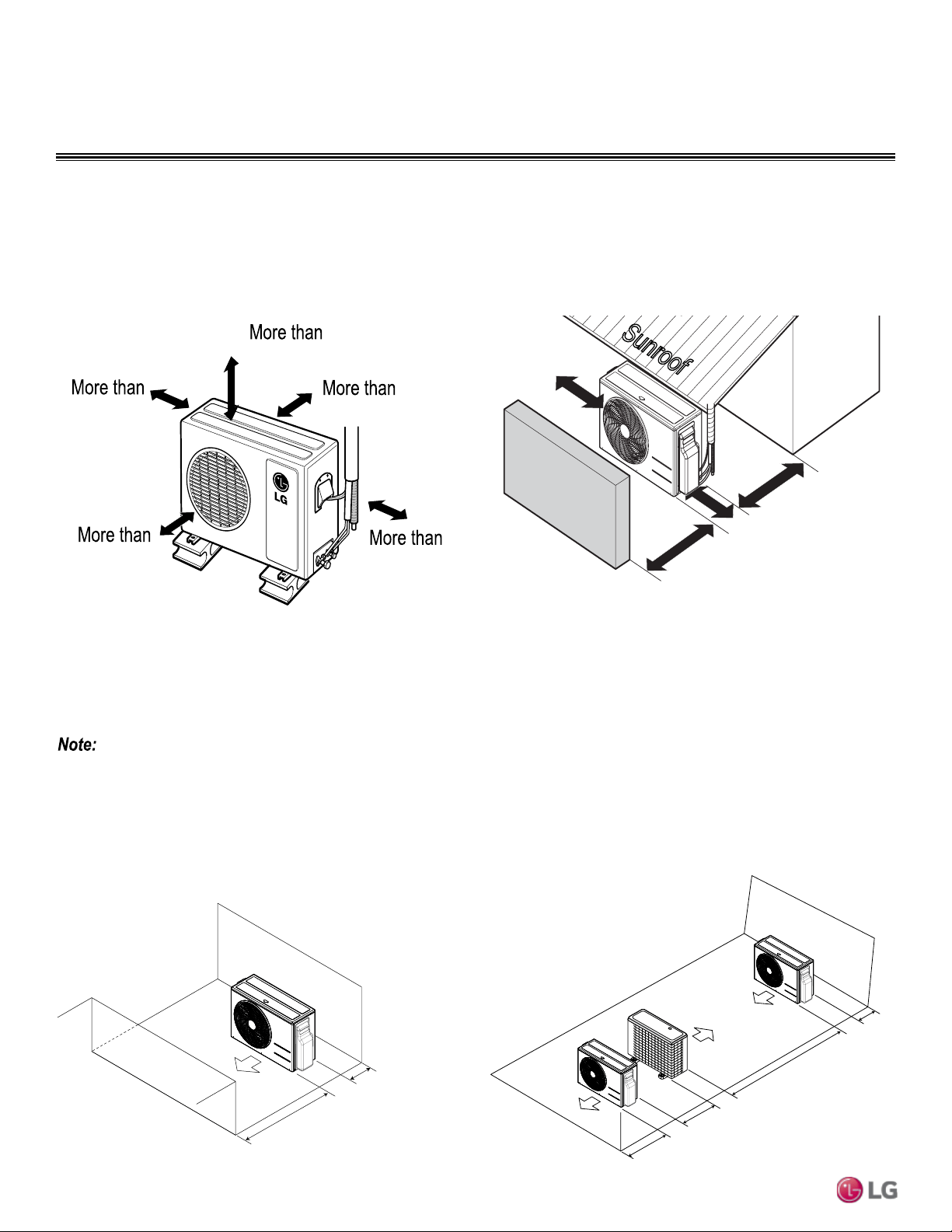
56 | APPLICATION GUIDELINES
Single Zone Mega Wall Mounted Engineering Manual
Due to our policy of continuous product innovation, some specications may change without notication.
©
LG Electronics U.S.A., Inc., Englewood Cliffs, NJ. All rights reserved. “LG ” is a registered trademark of LG Corp.
Outdoor Unit Clearances
PLACEMENT CONSIDERATIONS
Minimum Clearance Requirements for Single-Zone Mega Systems
Proper clearance for the outdoor unit coil is critical for proper unit operation. When installing the outdoor unit, consider service, inlet and
outlet and minimum allowable space requirements as illustrated in the diagrams below.
Specific clearance requirements in the diagram below are for the single-zone Art Cool Premier wall mount systems. Figure 26 shows the
overall minimum clearances that must be observed for safe operation and adequate airflow around the outdoor unit.
Figure 26: Outdoor Unit Clearances.
12
28
24
12
24
Unit : inch
When placing the outdoor unit under an overhang, awning, sunroof or other “roof-like structure”, observe the clearance requirements (as
shown in Figure 27) for height in relation to the unit. This clearance ensures that heat radiation from the condenser is not restricted around
the unit.
Adhere to all clearance requirements if installing the unit on a roof. Be sure to level the unit and ensure that the unit is adequately anchored.
Consult local codes for rooftop mounting requirements.
Do not place the unit where animals and/or plants will be in the path of the warm air, or where the warm air and/or noise will disturb neighbors.
Figure 27: Outdoor Unit Sunroof/Awning Clearances.
More than
12
More than
12
Sunroof
Fence or
obstacles
More than
28
Unit : inch
More than
24
Minimum
28
Minimum
12
ODU Service Access & Clearances
Unit: Inch
In order to have successful service access to the out door unit, see Figure 28 for minimum spacing. When installing multiple outdoor units,
see Figure 29 for correct spacing requirements.
Minimum
Minimum
12
79
24
28
Unit: Inch
Multiple ODUs
Service Access & Clearances
Figure 28: ODU Service Access Clearance - Single Unit. Figure 29: ODU Service Access Clearance - Multiple Units.

REFRIGERANT PIPING
DESIGN & LAYOUT
BEST PRACTICES
“Refrigerant Piping Design” on page 58
"Selecting Field-Supplied Copper Tubing" on page 59
"Refrigerant Piping System Layout" on page 60
"Piping Connection" on page 59
"Electrical Connections" on page 64
"Mechanical Specifications" on page 66
"Acronyms" on page 67
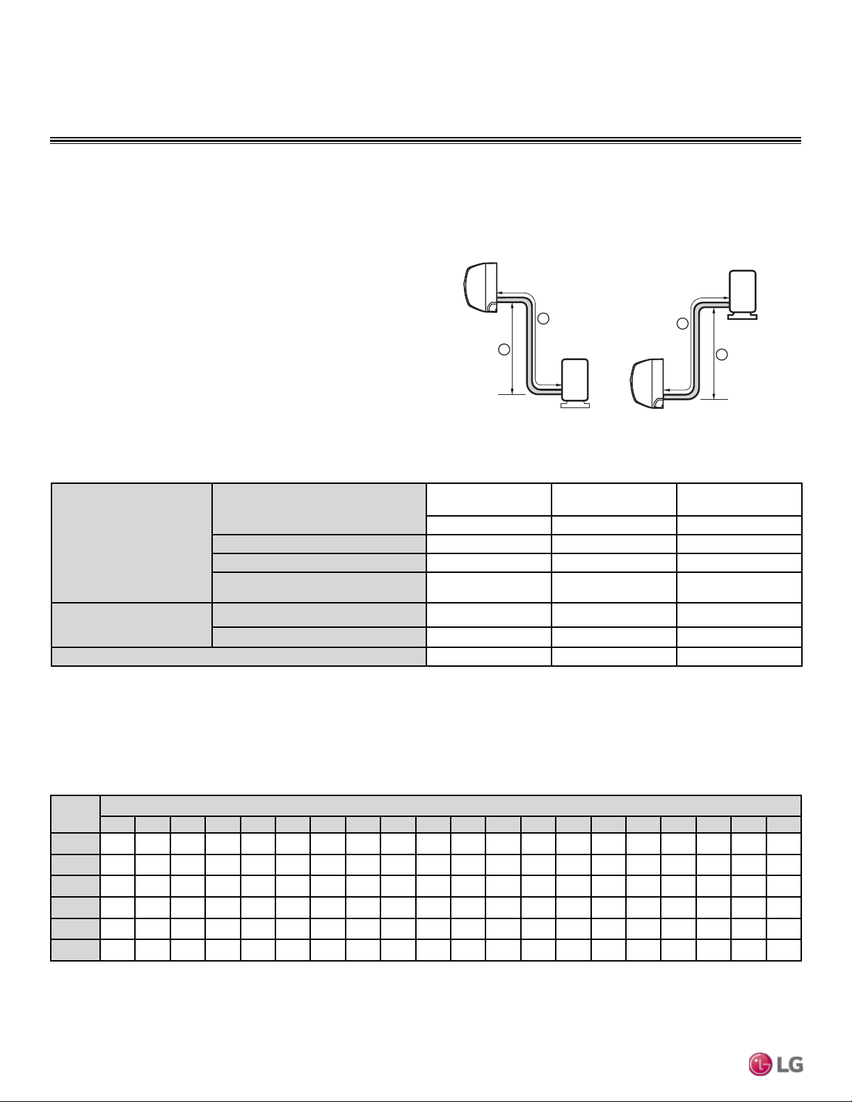
Due to our policy of continuous product innovation, some specications may change without notication.
©
LG Electronics U.S.A., Inc., Englewood Cliffs, NJ. All rights reserved. “LG ” is a registered trademark of LG Corp.
58 | REFRIGERANT DESIGN
Single Zone Mega Wall Mounted Engineering Manual
REFRIGERANT PIPING DESIGN
Design Guideline Summary/Selecting Field-Supplied Copper Tubing
Table 12: Single-Zone Mega Wall Mount Refrigerant Piping System Limitations.
Pipe Length
(ELF = Equivalent Length of
pipe in Feet)
Longest total equivalent piping length
LS090HEV1/
LS120HEV1
LS180HEV1/
LS240HEV1
LSU090HXV/
LSU120HXV
49.2 feet 65.6 feet 49.2 feet
Shortest total equivalent piping length
9.8 feet 9.8 feet 6.6 feet
Piping Length (no additional refrigerant)
24.6 feet 24.6 feet 24.6 feet
Distance between fittings and indoor or
outdoor units
≥20 inches ≥20 inches ≥20 inches
Elevation
(All Elevation Limitations are
Measured in Actual Feet)
If outdoor unit is above indoor unit
22.9 feet 32.8 feet 22.9 feet
If outdoor unit is below indoor unit
22.9 feet 32.8 feet 22.9 feet
Additional Refrigerant Needed (oz/ft)
0.22 0.33 0.22
Figure 30: Mega System Layout.
Max Length = A
Max Elevation = B
Unit = Feet
Outdoor unit
Indoor unit
A
B
Outdoor unit
Indoor unit
A
B
Device Connection Limitations
Single-zone systems consist of one outdoor unit and one indoor
unit. One of the most critical elements of a single zone system is
the refrigerant piping. Table 12 lists pipe length limits that must be
followed in the design of a Single Zone Art Cool Premier refrigerant
pipe system. Refer to Figure 30 for maximum length and elevation of
piping.
Pipe
Length
1
Fluid Temperature °F
35° 40° 45° 50° 55° 60° 65° 70° 75° 80° 85° 90° 95° 100° 105° 110° 115° 120° 125° 130°
10
0.04 0.04 0.05 0.06 0.06 0.07 0.08 0.08 0.09 0.09 0.10 0.10 0.11 0.11 0.11 0.12 0.13 0.14 0.15 0.15
20
0.08 0.08 0.10 0.12 0.13 0.14 0.15 0.16 0.17 0.18 0.19 0.20 0.21 0.22 0.22 0.23 0.26 0.28 0.29 0.30
30
0.12 0.12 0.15 0.18 0.20 0.21 0.23 0.24 0.26 0.27 0.29 0.30 0.32 0.33 0.32 0.35 0.39 0.42 0.44 0.45
40
0.16 0.16 0.20 0.24 0.26 0.28 0.30 0.32 0.34 0.36 0.38 0.40 0.42 0.44 0.43 0.46 0.52 0.56 0.58 0.60
50
0.20 0.20 0.25 0.30 0.33 0.35 0.38 0.40 0.43 0.45 0.48 0.50 0.53 0.55 0.54 0.58 0.65 0.70 0.73 0.75
60
0.24 0.24 0.30 0.36 0.39 0.42 0.45 0.48 0.51 0.54 0.57 0.60 0.63 0.66 0.65 0.69 0.78 0.84 0.87 0.90
1
Pipe length baseline temperature = 0°F. "Expansion of Carbon, Copper and Stainless Steel Pipe," The Engineers' Toolbox, www.engineeringtoolbox.com.
Table 13: Linear Thermal Expansion of Copper Tubing in Inches
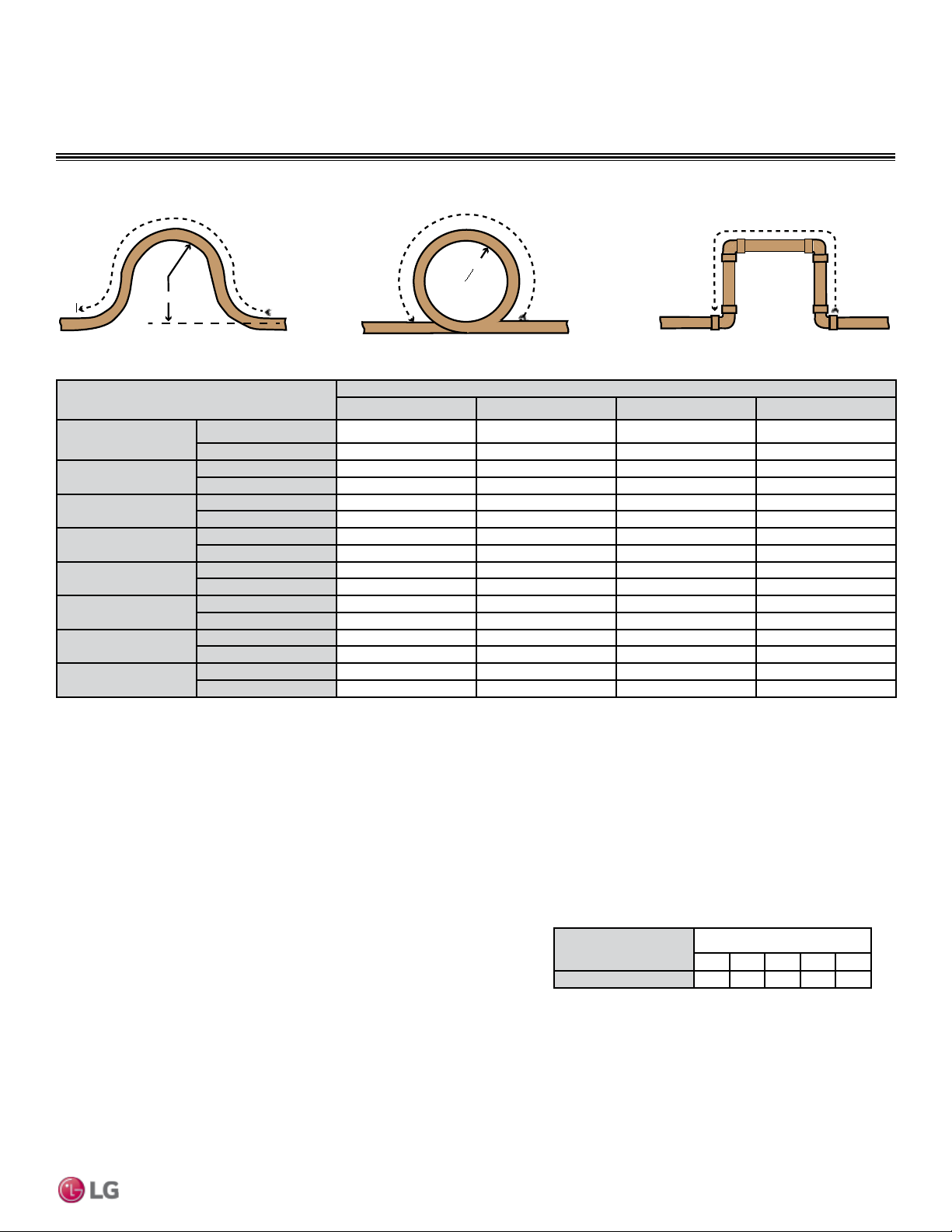
Due to our policy of continuous product innovation, some specications may change without notication.
©
LG Electronics U.S.A., Inc., Englewood Cliffs, NJ. All rights reserved. “LG ” is a registered trademark of LG Corp.
REFRIGERANT DESIGN | 59
Refrigerant Piping Design & Layout Best Practices
REFRIGERANT PIPING DESIGN
Selecting Field-Supplied Copper Tubing
Figure 31: Coiled Expansion Loops and Offsets.
Anticipated Linear
Expansion (LE) (inches)
Nominal Tube Size (OD) inches
1/4 3/8 1/2 3/4
1/2
R
1
6 7 8 9
L
2
38 44 50 59
1
R
1
9 10 11 13
L
2
54 63 70 83
1-1/2
R
1
11 12 14 16
L
2
66 77 86 101
2
R
1
12 14 16 19
L
2
77 89 99 117
2-1/2
R
1
14 16 18 21
L
2
86 99 111 131
3
R
1
15 17 19 23
L
2
94 109 122 143
3-1/2
R
1
16 19 21 25
L
2
102 117 131 155
4
R
1
17 20 22 26
L
2
109 126 140 166
Table 14: Radii of Coiled Expansion Loops and Developed Lengths of Expansion Offsets.
Large Tubing U-bend (>3/4 in.) Loop Small Tubing U-bend (<3/4 in.)
R
L
R
L
L
1
R = Centerline Length of Pipe.
2
L = Centerline Minimum Radius (inches).
Physical Pipe Length: Actual length of straight segment(s) of pipe.
Equivalent Pipe Length: Actual length of pipe plus equivalent lengths of elbows and valves.
1. Draft a one-line diagram of the proposed piping system connecting outdoor unit to indoor unit. Follow the pipe limitations listed on page
58.
2. Calculate the physical length of each pipe segment and note it on the drawing.
3. Calculate the equivalent pipe length of each pipe segment.
Definitions
Layout Procedure
Field-Provided Isolation Ball Valves
It is acceptable to install field-supplied ball valves with Schrader ports at the indoor unit. Full-port isolation ball valves with Schrader ports
(positioned between valve and indoor unit) rated for use with R410A refrigerant should be used on both the liquid and vapor lines.
If valves are not installed and the indoor unit needs to be removed or repaired, the entire system must be shut down and evacuated. Position
valves with a minimum distance of three (3) to six (6) inches of pipe on either side of the valve. Valves must be easily accessible for service.
If necessary, install drywall access doors or removable ceiling panels, and position the valves to face the access door or ceiling panel open-
ing. Mount valves with adequate space between them to allow for placement of adequate pipe insulation around the valves. Recommended
best practice is to clearly label and document locations of all service valves. The equivalent pipe length of each ball valve must be added to
each pipe segment.
Using Elbows
Field-supplied elbows are allowed as long as they are long radius and designed
for use with R410A refrigerant. The designer should be cautious with the quantity
and size of fittings used, and must account for the additional pressure losses in
equivalent pipe length calculation. The equivalent pipe length of each elbow must
be added to each pipe segment. See Table 15 for equivalent lengths.
Table 15: Equivalent Piping Length for Piping Components.
Component
Size (Inches)
1/4 3/8 1/2 5/8 3/4
Long Radius Elbow (ft.)
0.5 0.6 0.7 0.8 1.2
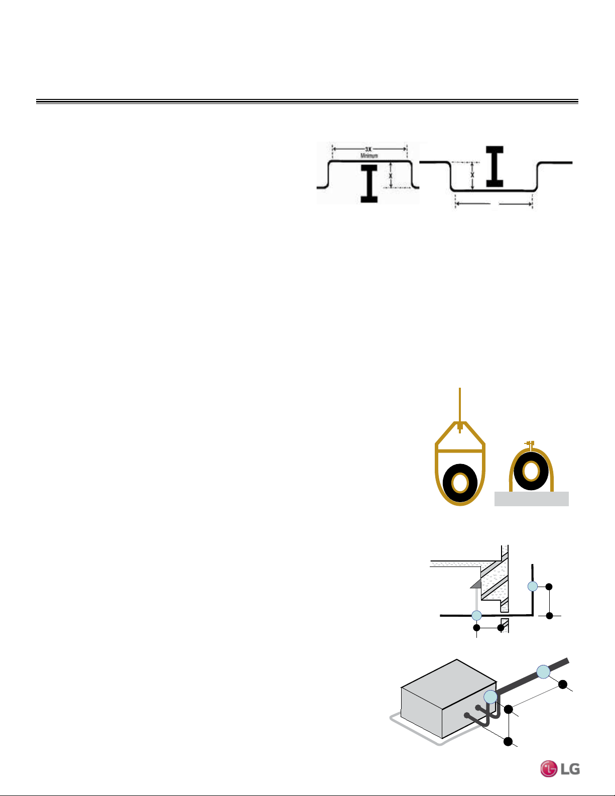
Due to our policy of continuous product innovation, some specications may change without notication.
©
LG Electronics U.S.A., Inc., Englewood Cliffs, NJ. All rights reserved. “LG ” is a registered trademark of LG Corp.
60 | REFRIGERANT DESIGN
Single Zone Mega Wall Mounted Engineering Manual
INSTALLATION & LAYOUT BEST PRACTICES
Refrigerant Piping System Layout
Figure 32: Installing Piping Above and Below an Obstacle
Above an obstacle.
3X
Below an obstacle.
Minimum
Obstacles
When an obstacle, such as an I-beam or concrete T, is in the path
of the planned refrigerant pipe run, it is best practice to route the
pipe over the obstacle. If adequate space is not available to route
the insulated pipe over the obstacle, then route the pipe under the
obstacle. In either case, it is imperative the horizontal section of pipe
above or below the obstacle be a minimum of three (3) times greater
than the longest vertical rise (or fall) distance (Figure 32).
No Pipe Size Substitutions
Using a different size is prohibited and may result in a system malfunction or failure to work at all.
In-line Refrigeration Components
Components such as oil traps, solenoid valves, filter-dryers, sight glasses, tee fittings, and other after-market accessories are not permitted
on the refrigerant piping system between the outdoor unit and the indoor unit. Single Zone Mega Inverter Wall Mounted air-source systems
are provided with redundant systems that assure oil is properly returned to the compressor. Sight-glasses and solenoid valves may cause
vapor to form in the liquid stream. Over time, dryers may deteriorate and introduce debris into the system. The designer and installer should
verify the refrigerant piping system is free of traps, sagging pipes, sight glasses, filter dryers, etc.
Pipe Supports
A properly installed pipe system should be adequately supported
to avoid pipe sagging. Sagging pipes become oil traps that lead to
equipment malfunction.
Pipe supports should never touch the pipe wall; supports shall be
installed outside (around) the primary pipe insulation jacket (see
Figure 33). Insulate the pipe first because pipe supports shall be
installed outside (around) the primary pipe insulation jacket. Clevis
hangers should be used with shields between the hangers and
insulation. Field provided pipe supports should be designed to
meet local codes. If allowed by code, use fiber straps or split-ring
hangers suspended from the ceiling on all-thread rods (fiber straps
or split ring hangers can be used as long as they do not compress
the pipe insulation). Place a second layer of insulation over the pipe
insulation jacket to prevent chafing and compression of the primary
insulation within the confines of the support pipe clamp.
A properly installed pipe system will have sufficient supports to avoid
pipes from sagging during the life of the system. As necessary,
place supports closer for segments where potential sagging could
occur. Maximum spacing of pipe supports shall meet local codes.
If local codes do not specify pipe support spacing, pipe shall be
supported as follows:
• Maximum of five feet (5′) on center for straight segments of pipe up
to 3/4" outside diameter size.
Wherever the pipe changes direction, place a hanger within twelve
(12) inches on one side and within twelve to nineteen (12 to 19)
inches of the bend on the other side as shown in Figure 35.
Figure 33: Pipe Hanger Details
Figure 34: Typical Pipe Support
Location—Change in Pipe Direction
Figure 35: Pipe Support at
Indoor Unit
Max. 12"
~ 12" – 19"
A
B
A + B ~ 12" – 19"
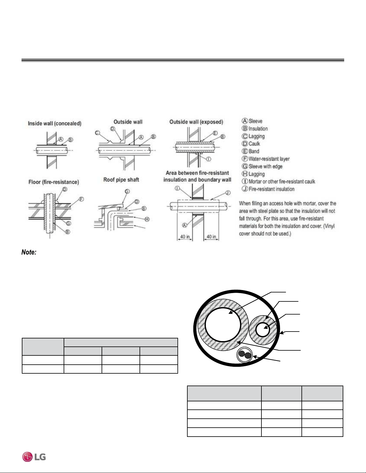
Due to our policy of continuous product innovation, some specications may change without notication.
©
LG Electronics U.S.A., Inc., Englewood Cliffs, NJ. All rights reserved. “LG ” is a registered trademark of LG Corp.
REFRIGERANT DESIGN | 61
Refrigerant Piping Design & Layout Best Practices
Refrigerant Piping System Layout
Figure 36: Pipe Sleeve Options.
Underground Refrigerant Piping
Refrigerant pipe installed underground should be routed inside a
vapor tight protective sleeve to prevent insulation deterioration and
water infiltration. Refrigerant pipe installed inside underground
casing must be continuous without any joints. Underground refriger-
ant pipe must be located at a level below the frost line.
Figure 37: Typical Arrangement of Refrigerant Pipe and Cable(s) in a
Utility Conduit.
INSTALLATION & LAYOUT BEST PRACTICES
Diameter of penetrations shall be determined by pipe diameter plus the thickness of the insulation.
Pipe Sleeves at Penetrations
LG requires that all pipe penetrations through walls, floors, and pipes buried underground be properly insulated and routed through an ap-
propriate wall sleeve of sufficient size to prevent compression of refrigerant pipe insulation and free movement of the pipe within the sleeve
(Figure 36). Underground refrigerant pipe shall be routed inside a protective sleeve to prevent insulation deterioration.
Table 16: Utility Conduit Sizes (Inches)
1
OD pipe diameter in inches; Values in parenthesis () indicate OD of pipe with insulation jacket.
2
Diameter of pipe with insulation. Thickness of pipe insulation is typical. Actual required thickness may
vary based on surrounding ambient conditions and should be calculated and specified by the design
engineer.
3
Insulation thickness (value in parenthesis) = 3/8 inch.
4
Insulation thickness (value in parenthesis) = 3/4 inch.
Liquid Pipe
1
Vapor Pipe
1
3/8 (1-1/8
2,3
) 1/2 (2.0
2,4
) 5/8 (2-1/8
2,4
)
1/4 (1.0)
4
4 4 4
3/8 (1-1/8)
4
4 4 4
Model
Liquid Conn.
(inches)
Vapor Conn.
(inches)
LSU090HEV1, LSU120HEV1 1/4 3/8
LSU180HEV1 1/4 1/2
LSU240HEV1 1/4 5/8
LSU090HXV, LSU120HXV 1/4 3/8
Table 17: Outdoor Unit Refrigerant Pipe Connections (All Brazed Type).
Vapor Line
Liquid Line
Min. 18 Gauge
Cable
Power/Communication
Pi
p
e Sleeve
Insulation Material
Insulation
Material
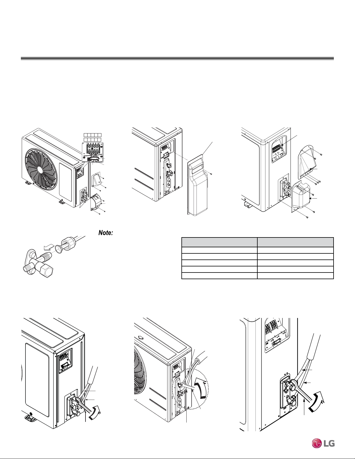
Due to our policy of continuous product innovation, some specications may change without notication.
©
LG Electronics U.S.A., Inc., Englewood Cliffs, NJ. All rights reserved. “LG ” is a registered trademark of LG Corp.
62 | REFRIGERANT DESIGN
Single Zone Mega Wall Mounted Engineering Manual
Refrigerant Piping System Layout
INSTALLATION & LAYOUT BEST PRACTICES
Table 18: Torque Wrench Tightening
Figure 38: LSU90-120HEV1, LSU90-120HXV
Outdoor Unit Connection Cover Removal.
Figure 39: LSU180HEV1 Outdoor Unit Con-
nection Cover Removal.
Conduit cover
Piping connection
Tubing cover
Terminal Block
1(L1) 2(L2)1(L1) 2(L2)
3
Power
connecting
cable
Power
cord
Cord clamp
90-120HEV1
1(L) 2(N)L N
3
90-120HXV
Single Zone Mega Outdoor Unit Connections
1. Remove the tubing cover from the unit by loosening the fastening screws.
2. Align the center of the refrigerant pipe and corresponding connection as shown, and tighten the flare nut initially by hand.
3. Finish tightening the flare nut with a torque wrench until the wrench clicks. Follow the guidelines as outlined in Table 18 for the amount of
torque to use.
When tightening the are nut with
torque wrench, ensure the direc-
tion for tightening follows the ar-
row on the wrench.
Tubing cover
Figure 40: LSU240HEV1 Outdoor Unit
Connection Cover Removal.
Tubing
Cover
Terminal
Block Cover
Terminal Block
Figure 41: Pipe Attachment.
Outdoor unit
Gas side piping
(Bigger diameter)
Liquid side piping
(Smaller diameter )
Torque wrench
Figure 42: LSU90-120HEV1, LSU90-120HXV
Outdoor Unit Piping Connection.
Figure 43: LSU180HEV1 Outdoor Unit
Piping Connection.
Torque wrench
Liquid side piping
(Smaller diameter)
Gas side piping
(Bigger diameter)
Outdoor unit
Liquid side piping
(Smaller diameter)
To rque wrench
Gas side piping
(Bigger diameter)
Outdoor unit
Figure 44: LSU240HEV1 Outdoor Unit Pip-
ing Connection.
Outside Diameter (Inches) Torque (Lbs.-ft)
1/4 13-18
3/8 24.6-30.4
1/2 39.8-47.7
5/8 45.6-59.3
3/4 71.6-87.5
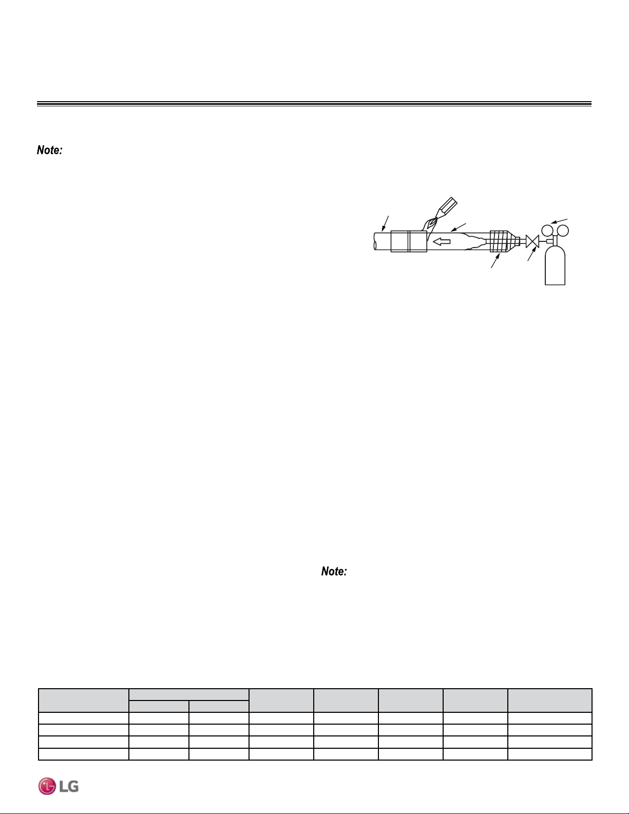
Due to our policy of continuous product innovation, some specications may change without notication.
©
LG Electronics U.S.A., Inc., Englewood Cliffs, NJ. All rights reserved. “LG ” is a registered trademark of LG Corp.
REFRIGERANT DESIGN | 63
Electrical Connections & Mechanical Specifications
INSTALLATION & LAYOUT BEST PRACTICES
Installation of Refrigerant Piping / Brazing Practices
Pressure-reducing
Valve
Valve
Taping
Nitrogen
Pipe to
be brazed
Refrigerant
Piping
Figure 45: Refrigerant Pipe Brazing.
Refrigerant Piping System Layout
Refrigerant Piping System Insulation
All refrigerant piping, field-provided isolation ball valves, service valves, and elbows shall be completely insulated using closed cell pipe
insulation. The liquid and vapor lines must be insulated separately.
To prevent heat loss/heat gain through the refrigerant piping, all refrigerant piping including liquid lines, and vapor lines shall be insulated
separately. Insulation shall be a minimum 1/2″ thick, and thickness needs to be increased based on ambient conditions and local codes.
All insulation joints are to be glued with no air gaps. Insulation material must fit snugly against the refrigeration pipe with no air space
between it and the pipe. Insulation passing through pipe hangers, inside conduit, and/or sleeves must not be compressed. Protect insulation
inside hangers and supports with a second layer. All pipe insulation exposed to the sun and outdoor elements shall be properly protected
with PVC, aluminum vapor barrier, or alternatively placed in a weather-resistant enclosure such as a pipe rack with a top cover; and meet
local codes.
The design engineer performs calculations to determine if the factory-supplied insulation jackets are sufficient to meet local codes and avoid
sweating. Add additional insulation if necessary. Mark all pipes at the point where the insulation jacket ends. Remove the jacket. Install
field provided insulation on the run-out and main trunk pipes first. Peel the adhesive glue protector slip from the insulation jacket and install
the clam-shell jacket over the fitting.
All joints are brazed in the field. Single Zone Mega refrigeration system com-
ponents contain very small capillary tubes, small orifices, electronic expansion
valves, oil separators, and heat exchangers that can easily become blocked.
Proper system operation depends on the installer using best practices and utmost
care while assembling the piping system (see Figure 45).
• While brazing, use a dry nitrogen purge operating at a minimum pressure of three
(3) psig and maintain a steady flow.
• Blow clean all pipe sections with dry nitrogen prior to assembly.
• Use a tubing cutter, do not use a saw to cut pipe. De-burr and clean all cuts
before assembly.
• Store pipe stock in a dry place. Keep pipe capped and clean.
• Use adapters to assemble different sizes of pipe.
• Do not use flux, soft solder, or anti-oxidant agents.
• Use a 15% silver phosphorous copper brazing alloy to avoid overheating and produce good flow.
• Protect isolation valves, electronic expansion valves, and other heat-sensitive control components from excessive heat with a wet rag or a
heat barrier spray product
Keep the piping system free of contaminants and debris such as copper burrs, slag, or carbon dust during installation.
Charging
Each outdoor unit is factory charged (nameplate charge) for the
evaporator as well as a standard 24.6 ft line. Any time a line set is
used longer then the standard 24.6 ft line set length, the refrigerant
charge has to be adjusted.
You must adjust the charge based on how many feet of piping are
added based on 0.22 or 0.33 oz of R410A per foot. The factory
charge accommodates pipe lengths up to the standard length without
requiring refrigerant removal.
Example: A 30 ft line set is used --
5.4 additional feet x 0.33 oz per ft = Add 1.78 oz
of R410A
If you are uncertain of the unit charge, reclaim, evacuate and weigh in
the correct charge using the unit nameplate (capacity) charge adjusting
for line sets longer than 24.6 ft. This will prevent any interruptions to the
functioning of the unit and possible damage.
Capacity
(Btu/h)/Model
Pipe Size
Standard
Length (ft)
Max.
Elevation (ft)
Max.
Length (ft)
Min.
Length (ft)
Additional
Refrigerant (oz/ft)
Vapor Liquid
9k, 12k/HEV1 3/8 1/4 24.6 22.9 49.2 9.8 0.22
9k, 12k/HXV 3/8 1/4 24.6 22.9 49.2 6.6 0.22
18k/HEV1 1/2 1/4 24.6 32.8 65.6 9.8 0.33
24k/HEV1 5/8 1/4 24.6 32.8 65.6 9.8 0.33
Table 19: Charging Capacity.
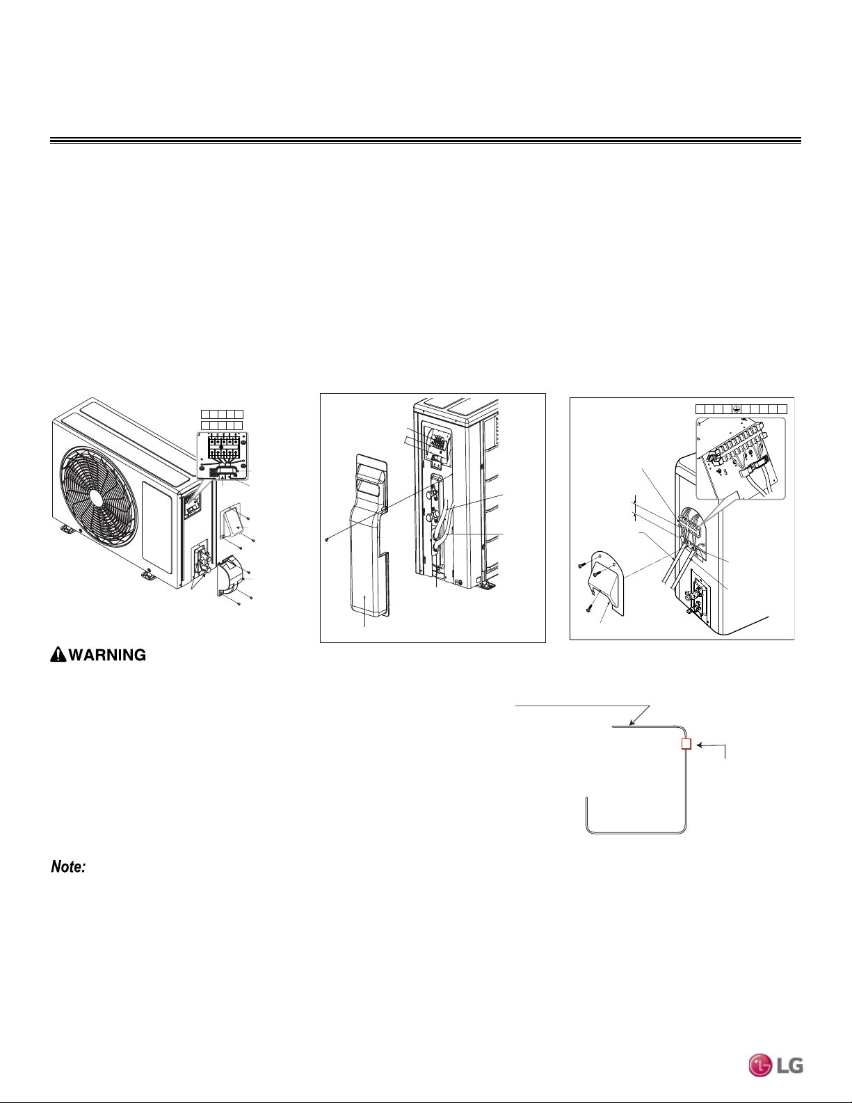
Due to our policy of continuous product innovation, some specications may change without notication.
©
LG Electronics U.S.A., Inc., Englewood Cliffs, NJ. All rights reserved. “LG ” is a registered trademark of LG Corp.
64 | REFRIGERANT DESIGN
Single Zone Mega Wall Mounted Engineering Manual
Figure 46: LSU90-120HEV1, LSU90-120HXV
Outdoor Unit Electrical Connection.
ELECTRICAL CONNECTIONS
Figure 47: LSU180HEV1 Outdoor Unit
Electrical Connection.
Figure 48: LSU240HEV1 Outdoor Unit
Electrical Connection.
Terminal Block
Connecting
Cable
Power
Supply
Cord
Conduit Panel
Tubing Cover
Over 0.2”
Terminal Block
Over 0.2”
Terminal Cover
Conduit Panel
Connecting
Cable
Power Supply
Cord
1(L1) 2(L2) 1(L1) 2(L2)
3
Outdoor Electrical Connection
1. Remove the control cover from the unit by loosening the fastening screw (Figures 46 to 48).
2. Take off the caps on the conduit panel.
3. Connect both the power supply and low voltage lines to the corresponding terminals on the terminal block (terminals block may be differ-
ent depending on model).
4. Be sure to ground the unit by following local codes.
5. Allow for enough length (add several inches) for each wiring.
6. Secure the cable with a cord clamp.
7. Secure conduit tubes with lock nuts.
8. Reattach the control cover to the original position with the fastening screw.
Conduit cover
Piping connection
Tubing cover
Terminal Block
1(L1) 2(L2)1(L1) 2(L2)
3
Power
connecting
cable
Power
cord
Cord clamp
90-120HEV1
1(L) 2(N)L N
3
90-120HXV
Figure 49: Circuit Breaker.
• Separately wire the high and low voltage lines. There is a risk of electric shock,
physical injury, or death.
• Use heat-proof electrical wire capable of withstanding temperatures up to
167°F to avoid wiring malfunction and electrical shock, which may cause
physical injury or death.
• Ensure you connect the wire firmly. Loose wiring may cause unit malfunction,
the wires to burnout or the terminal to overheat and catch fire. There is a risk
of electric shock, physical injury or death.
• Use outdoor and waterproof connection cable rated up to 300V for the connec-
tion between the indoor and outdoor unit to avoid electrical shock, which may
cause physical injury or death.
Air
Conditioner
Main Power Source
Circuit Breaker
Use a circuit breaker
or time delay fuse
• Separately wire the high and low voltage lines to avoid damage to unit.
• Use heat-proof electrical wire capable of withstanding temperatures up to 167°F to avoid damage to unit.
• Always use a circuit breaker or time delay fuse when connecting electrical wiring to the unit.
• Ensure you connect the wire firmly. Loose wiring may cause unit malfunction, the wires to burnout or the terminal to overheat and catch
fire. There is a risk of equipment malfunction or property damage.
• Use outdoor and waterproof connection cable rated up to 300V for the connection between the indoor and outdoor unit to avoid damage
to the unit.
• Comply with local codes while running wire from the indoor unit to the outdoor unit.
• Do not allow wire to touch refrigerant tubing, the compressor or any moving parts since it can lead to mechanical failure.
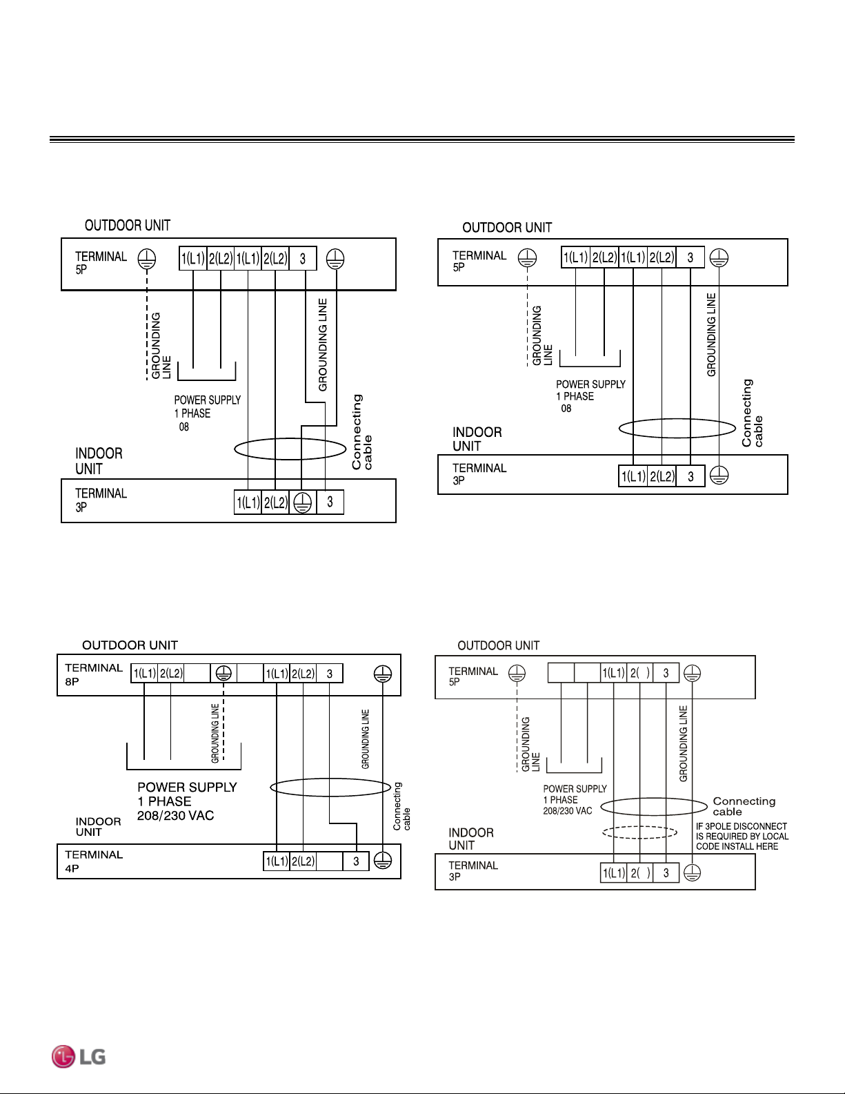
Due to our policy of continuous product innovation, some specications may change without notication.
©
LG Electronics U.S.A., Inc., Englewood Cliffs, NJ. All rights reserved. “LG ” is a registered trademark of LG Corp.
REFRIGERANT DESIGN | 65
Electrical Connections & Mechanical Specifications
ELECTRICAL CONNECTIONS
Figure 50: Terminal Block Wiring Diagram LS090HEV1
LS090HEV1
208/230 VA C
Figure 51: Terminal Block Wiring Diagram LS120HEV1
LS120HEV1
208/230 VA C
LS180HEV1, LS240HEV1
LSU090HXV, LSU120HXV
N
2(L2)
N
1(L1)
Figure 52: Terminal Block Wiring Diagram LS180HEV1, LS240HEV1 Figure 53: Terminal Block Wiring Diagram LS090HXV, LS120HXV

Due to our policy of continuous product innovation, some specications may change without notication.
©
LG Electronics U.S.A., Inc., Englewood Cliffs, NJ. All rights reserved. “LG ” is a registered trademark of LG Corp.
66 | REFRIGERANT DESIGN
Single Zone Mega Wall Mounted Engineering Manual
Single Zone Mega and Mega 115V
MECHANICAL SPECIFICATIONS
General
LG Single Zone Mega Wall Mounted system
comprises of a single outdoor unit connected
to a single indoor unit with a single refriger-
ant circuit.
An LG Single Zone Mega Inverter Wall
Mounted system is a Duct-Free Split system
that can operate in either cooling or heat-
ing mode. The system shall be capable of
changing mode within a maximum time of
three (3) minutes to ensure indoor tempera-
ture can be properly maintained.
LG Single Zone Mega systems are manu-
factured in a facility registered to ISO 9001
and ISO 14001, which is a set of standards
applying to environmental protection
set by the International Organization for
Standardization (ISO). The units are listed
by Intertek Electrical Testing Laboratories
(ETL) and bear the ETL label. Wiring in
these units are in accordance with the
National Electrical Code (NEC).
Temperature Ranges
Mega (HEV1)
Operating ranges for outdoor unit of 14°F to
118°F (DB) for cooling; 14°F to 65°F (WB)
for heating.
Operating ranges for indoor unit of 53°F to
75°F (WB) for cooling; 60°F to 86°F (DB) for
heating.
Mega 115V (HXV)
Operating ranges for outdoor unit of 14°F to
118°F (DB) for cooling; 14°F to 65°F (WB)
for heating.
Operating ranges for indoor unit of 53°F to
75°F (WB) for cooling; 60°F to 86°F (DB) for
heating.
Casing / Frame
Outdoor unit is constructed with pre-coated
metal (PCM).
Indoor unit is constructed of heavy duty
Acrylonitrile Butadiene Styrene (ABS) and
High Impact Polystyrene (HIPS) plastic.
Refrigerant System
The refrigeration system consists of a single
refrigeration circuit and uses R410A refriger-
ant. The outdoor unit is provided with factory
installed components, including a refriger-
ant strainer, check valves, oil separator,
accumulator, four-way reversing valve, EEV,
high and low side charging ports, service
valves, and interconnecting piping.
Refrigeration Oil Control
Heat Pump outdoor units have a centrifugal
oil separator and controls to ensure suf-
ficient oil supply is maintained, and that oil
does not travel with the refrigerant.
Compressors
The outdoor unit is equipped with one
hermetic digitally controlled inverter driven
rotary (9k/12k Btu/h systems) or twin-rotary
(18k/24k Btu/h systems) compressor to
modulate capacity (modulation in 1 Hz
increments).
Frequency ranges for the (HEV1) outdoor
units are:
9k Btu/h = 20 to 80 Hz
12k Btu/h = 20 to 90 Hz
18/24k Btu/h = 15 to 100 Hz
Frequency ranges for the (HXV) outdoor
units are:
9k Btu/h = 15 to 100 Hz
12k Btu/h = 15 to 100 Hz
Over-current protection and vibration isola-
tion are integrated with the compressor.
Outdoor Unit Coil
Heat Pump outdoor unit coils are of a
nonferrous construction with louvered fins
on copper tubing, and are protected with an
integral coil guard. Coil fins have a factory
applied corrosion resistant GoldFin™ mate-
rial with hydrophilic coating.
Fans and Motors
The outdoor unit includes one direct drive,
variable speed propeller type fan.
The Brushless Digitally Controlled (BLDC)
fan motor has inherent protection, perma-
nently lubricated bearings, and variable
speed with a maximum speed up to 950 rpm.
Raised guards are provided to limit contact
with moving parts.
The outdoor unit has horizontal discharge
airflow.
Electrical
The HEV model unit is available in a
208-230V 60 Hz, 1-phase power supply.
The HXV model unit is available in a 115V
60 Hz, 1-phase power supply. The units are
capable of operating within voltage limits of
±10% rated voltage, and include overcurrent
protection.
Controls
The unit is factory wired with necessary
electrical control components, integral
microprocessors, printed circuit boards,
thermistors, sensors, terminal blocks, and
lugs for power wiring.
Microprocessor-based algorithms provide
component protection, soft-start capability,
refrigeration system pressure, temperature,
defrost, and ambient control.
Due to our policy of continuous product innovation, some specications may change without notication.
©
LG Electronics U.S.A., Inc., Englewood Cliffs, NJ. All rights reserved. “LG ” is a registered trademark of LG Corp.
REFRIGERANT DESIGN | 67
Electrical Connections & Mechanical Specifications
Table 20: Table of Acronyms
ACRONYMS
ABS
Acrylonitrile Butadiene Styrene
IDU
Indoor Unit
AC
Air Conditioner
ISO
International Organization for Standardization
ACP
Advanced Control Platform
kW
Kilo Watts
ASHRAE
American Society of Heating, Refrigeration, and
Air Conditioning
LED
Light Emitting Diode
AWG
American Wire Gauge
MBh
Thousands BTUs per hour
BLDC
Brushless Digitally Controlled/Direct
MCA
Maximum Circuit Ampacity
Btu/h
British Thermal Units per hour
MOP
Maximum Overcurrent Protection
BUS
Binary Unit System
MSC
Maximum Starting Current
CFM
Cubic Feet per Minute
NC
Noise Criterion (regarding Sound Pressure Levels)
COP
Coefficient Of Performance
NEC
National Electrical Code
CR
Combination Ratio
ODU
Outdoor Unit
DB
Dry Bulb
PCB
Printed Circuit Board
dB(A)
Decibels with “A” frequency weighting
PCM
Pre-Coated Metal
DDOAS
Decoupled Dedicated Outdoor Air
PDI
Power Distribution Indicator
DI
Digital Input
PI
Power Input
DO
Digital Output
PTAC
Packaged Terminal Air Conditioner
DPST
Double-Pole Single-Throw (switch)
PVC
Polyvinyl Chloride
EEV
Electronic Expansion Valve
SW or
S/W
Switch
ELF
Equivalent Length in Feet
USB
Universal Serial BUS
ESP
External Static Pressure
VAC
Voltage Alternating Current
ETL
Electronic Testing Laboratories
VAV
Variable Air Volume
HIPS
High Impact Polystyrene
VRF
Variable Refrigerant Flow
H/M/L
High/Medium/Low
WB
Wet Bulb
HVAC
Heating, Ventilation and Air Conditioning
LG Electronics
Commercial Air Conditioning Division
11405 Old Roswell Road
Alpharetta, Georgia 30009
www.lghvac.com
EM-SZ_Mega_Mega115V-4-15
Supersedes: EM-SZ_Mega_Mega115V-10-14
DFS-EM-AL-001-US_014D09
20001747 ISO 9001: 2008
LG ELECTRONICS INC.
LG Electronics Commercial Products Support
1-888-865-3026 USA
Follow the prompts for commercial A/C products.