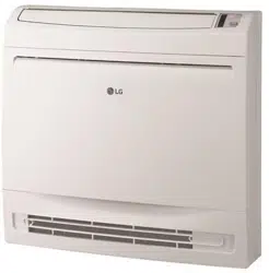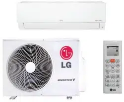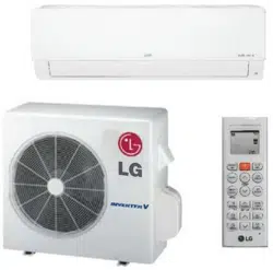

Single Zone Mega: LS090HEV2, LS120HEV2, LS180HEV2, LS240HEV2
Single Zone Standard Eciency: LS090HFV3, LS120HFV3, LS180HFV3, LS240HFV3
Single Zone Mega 115V: LS090HXV2, LS120HXV2
SINGLE ZONE MEGA, STANDARD EFFICIENCY,
AND MEGA 115V WALL MOUNTED
INSTALLATION MANUAL
The instructions included in this manual must be followed to prevent product malfunction, property damage, injury, or death to the user or
other people. Incorrect operation due to ignoring any instructions will cause harm or damage. The level of seriousness is classified by the
symbols described below.
Do not throw away, destroy, or lose this manual.
Please read carefully and store in a safe place for future reference.
Content familiarity required for proper installation.
A summary list of safety precautions begins on page 3.
For more technical materials such as submittals, engineering
databooks, and catalogs, visit www.lghvac.com.
For continual product development, LG Electronics U.S.A., Inc., reserves the right to change specifications without notice.
©LG Electronics U.S.A., Inc.
This document, as well as all reports, illustrations, data, information, and other materials are the property of LG Electronics U.S.A., Inc.
PROPRIETARY DATA NOTICE
This document, as well as all reports, illustrations, data, information, and
other materials are the property of LG Electronics U.S.A., Inc., and are
disclosed by LG Electronics U.S.A., Inc., only in confidence.
This document is for design purposes only.
3
Safety Instructions
Due to our policy of continuous product innovation, some specifications may change without notification.
©LG Electronics U.S.A., Inc., Englewood Cliffs, NJ. All rights reserved. “LG” is a registered trademark of LG Corp.
SAFETY INSTRUCTIONS
The instructions below must be followed to prevent product malfunction, property damage, injury or death to the user or other people. Incor-
rect operation due to ignoring any instructions will cause harm or damage. The level of seriousness is classified by the symbols described
below.
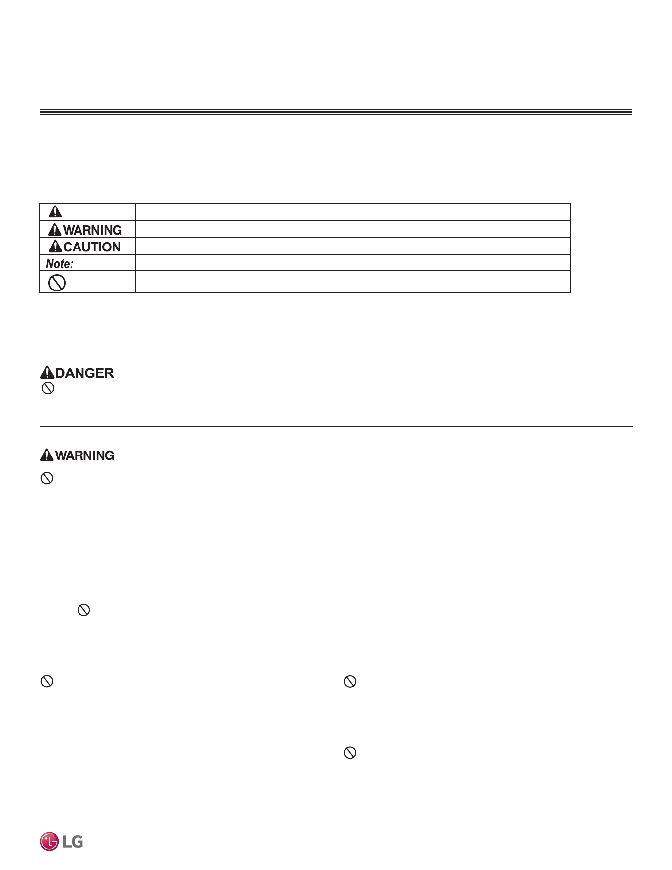
TABLE OF SYMBOLS
Do not install or remove the unit by yourself (end user).
Ask the dealer or an LG trained service provider to install the
unit.
Improper installation by the user will result in water leakage, re,
explosion, electric shock, physical injury or death.
For replacement of an installed unit, always contact an LG
trained service provider.
There is risk of re, electric shock, explosion, and physical injury or death.
The unit is shipped with refrigerant and the service valves
closed. Do not open service valves on the unit until all
non-condensibles have been removed from the piping sys-
tem and authorization to do so has been obtained from the
commissioning agent.
There is a risk of physical injury or death.
Do not run the compressor with the service valves
closed.
There is a risk of explosion, physical injury, or death.
Periodically check that the outdoor frame is not damaged.
There is a risk of explosion, physical injury, or death.
Replace all control box and panel covers.
If cover panels are not installed securely, dust, water and animals will
enter the unit, causing re, electric shock, and physical injury or death.
Always check for system refrigerant leaks after the unit has
been installed or serviced.
Exposure to high concentration levels of refrigerant gas will lead to illness
or death.
Wear protective gloves when handling equipment. Sharp
edges will cause personal injury.
Dispose the packing materials safely.
• Packing materials, such as nails and other metal or wooden parts,
will cause puncture wounds or other injuries.
• Tear apart and throw away plastic packaging bags so that children do
not play with them and risk suffocation and death.
Install the unit considering the potential for strong winds or
earthquakes.
Improper installation will cause the unit to fall over, resulting in physical
injury or death.
Do not change the settings of the protection devices.
If the pressure switch, thermal switch, or other protection device is
shorted and forced to operate improperly, or parts other than those
specied by LG are used, there is risk of re, electric shock, explosion,
and physical injury or death.
Do not install the unit on a defective stand.
There is a risk of physical injury.
INSTALLATION
Don’t store or use ammable gas / combustibles near the unit.
There is risk of re, explosion, and physical injury or death.
This symbol indicates an imminently hazardous situation which, if not avoided, will result in death or serious injury.
This symbol indicates a potentially hazardous situation which, if not avoided, could result in death or serious injury.
This symbol indicates a potentially hazardous situation which, if not avoided, may result in minor or moderate injury.
This symbol indicates situations that may result in equipment or property damage accidents only.
This symbol indicates an action must not be completed.
DANGER

4
Single Zone Mega, Standard Eciency, and Mega 115V Wall Mounted Installation Manual
Due to our policy of continuous product innovation, some specifications may change without notification.
©LG Electronics U.S.A., Inc., Englewood Cliffs, NJ. All rights reserved. “LG” is a registered trademark of LG Corp.
SAFETY INSTRUCTIONS
INSTALLATION - CONTINUED
Don’t install the unit where it’s directly exposed to ocean
winds.
Ocean winds will cause corrosion, particularly on the condenser and
evaporator ns, which, in turn could cause product malfunction or inef-
cient performance.
When installing the unit in a low-lying area, or a location that
is not level, use a raised concrete pad or concrete blocks to
provide a solid, level foundation.
This will prevent water damage and reduce abnormal vibration.
Properly insulate all cold surfaces to prevent “sweating.”
Cold surfaces such as uninsulated piping can generate condensate that
will drip and cause a slippery surface condition and/or water damage to
walls.
When installing the unit in a hospital, mechanical room, or
similar electromagnetic eld (EMF) sensitive environment,
provide sucient protection against electrical noise.
Inverter equipment, power generators, high-frequency medical equipment,
or radio communication equipment will cause the air conditioner to operate
improperly. The unit will also affect such equipment by creating electrical
noise that disturbs medical treatment or image broadcasting.
Do not use the product for special purposes such as
preserving foods, works of art, wine coolers, or other
precision air conditioning applications. The equipment is
designed to provide comfort cooling and heating.
There is risk of property damage.
Do not make refrigerant substitutions. Use R410A only.
If a different refrigerant is used, or air mixes with original refrigerant, the
unit will malfunction and be damaged.
Keep the unit upright during installation to avoid vibration or
water leakage.
Do not install the unit in a noise sensitive area.
When connecting refrigerant tubing, remember to allow for
pipe expansion.
Improper piping will cause refrigerant leaks and system malfunction.
Take appropriate actions at the end of HVAC equipment life
to recover, recycle, reclaim or destroy R410A refrigerant
according to applicable U.S. Environmental Protection
Agency (EPA) rules.
Periodically check that the outdoor frame is not damaged.
There is a risk of equipment damage.
Install the unit in a safe location where nobody can step on or
fall onto it. Do not install the unit on a defective stand.
There is risk of unit and property damage.
Install the drain hose to ensure adequate drainage.
There is a risk of water leakage and property damage.
Don’t store or use ammable gas / combustibles near the
unit.
There is risk of product failure.
Always check for system refrigerant leaks after the unit has
been installed or serviced.
Low refrigerant levels will cause product failure
The unit is shipped with refrigerant and the service valves
closed. Do not open service valves on the unit until all
non-condensibles have been removed from the piping system
and authorization to do so has been obtained from the com-
missioning agent.
There is a risk of refrigerant contamination, refrigerant loss and equip-
ment damage.
Do not run the compressor with the service valves closed.
There is a risk of equipment damage.
Be very careful when transporting the product. Failure to follow these directions will result in minor or moderate physical injury.
• Do not attempt to carry the product without assistance.
• Some products use polypropylene bands for packaging. Do not use polypropylene bands to lift the unit.
• Suspend the unit from the base at specified positions.
• Support the unit a minimum of four points to avoid slippage from rigging apparatus.
If the air conditioner is installed in a small space, take
measures to prevent the refrigerant concentration from
exceeding safety limits in the event of a refrigerant leak.
Consult the latest edition of ASHRAE (American Society of Heating,
Refrigerating, and Air Conditioning Engineers) Standard 15. If the
refrigerant leaks and safety limits are exceeded, it could result in personal
injuries or death from oxygen depletion.
Install the unit in a safe location where nobody can step on or
fall onto it.
There is risk of physical injury or death.
Properly insulate all cold surfaces to prevent “sweating.”
Cold surfaces such as uninsulated piping can generate condensate that
could drip, causing a slippery surface that creates a risk of slipping, falling,
and personal injury.

5
Safety Instructions
Due to our policy of continuous product innovation, some specifications may change without notification.
©LG Electronics U.S.A., Inc., Englewood Cliffs, NJ. All rights reserved. “LG” is a registered trademark of LG Corp.
SAFETY INSTRUCTIONS
High voltage electricity is required to operate this system.
Adhere to the National Electrical Codes and these
instructions when wiring.
Improper connections and inadequate grounding can cause accidental
injury or death.
Always ground the unit following local, state, and National
Electrical Codes.
Turn the power o at the nearest disconnect before servicing
the equipment.
Electrical shock can cause physical injury or death.
Properly size all circuit breakers or fuses.
There is risk of re, electric shock, explosion, physical injury or death.
WIRING
The information contained in this manual is intended for use
by an industry-qualied, experienced, certied electrician
familiar with the U.S. National Electric Code (NEC) who is
equipped with the proper tools and test instruments.
Failure to carefully read and follow all instructions in this manual can
result in personal injury or death.
All electric work must be performed by a licensed electrician
and conform to local building codes or, in the absence of
local codes, with the National Electrical Code, and the
instructions given in this manual.
If the power source capacity is inadequate or the electric work is not per-
formed properly, it will result in re, electric shock, physical injury or death.
Refer to local, state, and federal codes, and use power wires
of sucient current capacity and rating.
Wires that are too small will generate heat and cause a re.
Secure all eld wiring connections with appropriate wire
strain relief.
Improperly securing wires will create undue stress on equipment power
lugs. Inadequate connections will generate heat, cause a re and physical
injury or death.
The information contained in this manual is intended for use by an industry-qualied, experienced, certied electrician famil-
iar with the U.S. National Electric Code (NEC) who is equipped with the proper tools and test instruments.
Failure to carefully read and follow all instructions in this manual can result in equipment malfunction and property damage,.

6
Single Zone Mega, Standard Eciency, and Mega 115V Wall Mounted Installation Manual
Due to our policy of continuous product innovation, some specifications may change without notification.
©LG Electronics U.S.A., Inc., Englewood Cliffs, NJ. All rights reserved. “LG” is a registered trademark of LG Corp.
SAFETY INSTRUCTIONS
Clean up the site after installation is nished, and check
that no metal scraps, screws, or bits of wiring have been left
inside or surrounding the unit.
Do not use this equipment in mission critical or special-
purpose applications such as preserving foods, works of art,
wine coolers or refrigeration. The equipment is designed to
provide comfort cooling and heating.
Do not block the inlet or outlet.
Unit will malfunction.
Securely attach the electrical part cover to the indoor unit
and the service panel to the outdoor unit.
Non-secured covers can result in malfunction due to dust or water in the
service panel.
Periodically verify the equipment mounts have not
deteriorated.
If the base collapses, the unit could fall and cause property damage
or product failure.
Do not allow water, dirt, or animals to enter the unit.
There is risk of unit failure.
OPERATION
Do not provide power to or operate the unit if it is ood-
ed or submerged.
There is risk of re, electric shock, physical injury or death.
Use a dedicated power source for this product.
There is risk of re, electric shock, physical injury or death.
Do not operate the disconnect switch with wet hands.
There is risk of re, electric shock, physical injury or death.
Periodically verify that the hardware securing the unit has
not deteriorated.
If the unit falls from its installed location, it can cause property damage,
product failure, physical injury or death.
If gas leaks out, ventilate the area before operating the unit.
If the unit is mounted in an enclosed, low-lying, or poorly ventilated area,
and the system develops a refrigerant leak, it will cause re, electric
shock, explosion, physical injury or death.
To avoid physical injury, use caution when cleaning or servicing the air conditioner.
Do not allow water, dirt, or animals to enter the unit.
There is risk of re, electric shock, physical injury or death.
Avoid excessive cooling, and periodically perform venti-
lation to the unit.
Inadequate ventilation is a health hazard.
Do not touch the refrigerant piping during or after
operation.
It can cause burns or frostbite.
Do not operate the unit with the panel(s) or protective
cover(s) removed; keep ngers and clothing away from
moving parts.
The rotating, hot, cold, and high-voltage parts of the unit can cause
physical injury or death.
Periodically verify the equipment mounts have not
deteriorated.
If the base collapses, the unit could fall and cause physical injury or death.
Periodically check power cord and plug for damage.
Cord must be replaced by the manufacturer, its service agent, or similar
qualied persons in order to avoid physical injury and/or electric shock.
Do not open the inlet grille of the unit during operation.
Do not operate the unit with the panels or guards re-
moved. Do not insert hands or other objects through the
inlet or outlet when the unit is plugged in. Do not touch
the electrostatic lter, if the unit includes one.
The unit contains sharp, rotating, hot, and high voltage parts that can
cause personal injury and/or electric shock.
Securely attach the electrical part cover to the indoor unit
and the service panel to the outdoor unit.
Non-secured covers can result in burns or electric shock due to dust or
water in the service panel.

7
Due to our policy of continuous product innovation, some specifications may change without notification.
©LG Electronics U.S.A., Inc., Englewood Cliffs, NJ. All rights reserved. “LG” is a registered trademark of LG Corp.
TABLE OF CONTENTS
Safety Instructions ............................................................................. 3-6
General Data ..................................................................................... 8-13
Unit Nomenclature ............................................................................... 8
Parts .................................................................................................... 9
Specications ............................................................................... 10-12
Electrical ............................................................................................ 13
General Installation Guidelines ..................................................... 14-25
Outdoor Unit Location Selection ................................................... 14-16
Required Outdoor Unit Clearances ................................................... 17
Rigging and Lifting / Outdoor Unit Mounting ................................. 18-19
Indoor Unit Location Selection / Required Clearances ...................... 20
Indoor Unit Mounting .................................................................... 21-25
General Refrigerant Piping System Information ......................... 26-35
Refrigerant Safety Standards ............................................................ 26
Device Connection Limitations .......................................................... 26
Selecting Field Supplied Piping ......................................................... 27
Copper Expansion and Contraction .............................................. 28-29
Piping Materials and Handling ........................................................... 30
Refrigerant System Engineering ................................................... 31-33
Flaring and Brazing Procedures ................................................... 34-35
Refrigerant Piping Connections .................................................... 36-46
Installation Overview ......................................................................... 36
Special Applications ........................................................................... 37
Outdoor Unit Connections ................................................................. 38
Indoor Unit Connections ............................................................... 39-41
Outdoor Unit Drain Piping / Indoor Unit Drain Hose ..................... 42-44
Bundling ............................................................................................. 44
Insulation ...................................................................................... 45-46
Electrical System Installation ........................................................ 47-57
Safety Guidelines .............................................................................. 47
Connections and Specications ................................................... 48-52
Controller Options .............................................................................. 53
Indoor Unit Electrical Connections ............................................... 54-55
Outdoor Unit Electrical Connections ............................................. 56-57
Final Installation Procedures ........................................................ 58-68
Triple Leak / Pressure Test ........................................................... 58-59
Deep Evacuation Test ................................................................... 59-60
Triple Evacuation Test................................................................... 60-61
Refrigerant Trim Charge, Finishing the Job .................................. 62-63
Reattaching the Indoor Unit Bottom Cover ........................................ 64
Air Filter Disassembly and Assembly ................................................ 65
Installing Batteries, Test Run, Performance Evaluation ..................... 66
Installer Mode, Cooling Only Mode ................................................... 67
Pump Down Procedure ..................................................................... 68
Troubleshooting ............................................................................. 69-73
LG SIMS - Self Diagnosis Functions ........................................... 69-70
Error Codes ................................................................................. 71-72
Refrigerant Leaks .............................................................................. 73
Installation Checklist ........................................................................... 74

8
Single Zone Mega, Standard Eciency, and Mega 115V Wall Mounted Installation Manual
Due to our policy of continuous product innovation, some specifications may change without notification.
©LG Electronics U.S.A., Inc., Englewood Cliffs, NJ. All rights reserved. “LG” is a registered trademark of LG Corp.
GENERAL DATA
Unit Nomenclature
Single Zone Wall Mount Indoor and Outdoor Units
LS
N 090 HEV 2
Type
N = Indoor Wall Mount Unit
U = Outdoor Heat Pump Unit
No N or U = System
Family
LA= Art Cool Premier / Gallery / Mirror
LS= High Efficiency Wall Mount / Standard / Mega
Generation or Revision
1 = First
2 = Second
3 = Third
4 = Fourth
Nominal Capacity
(Nominal cooling capacity in Btu/h)
090 = 9,000
120 = 12,000
180 = 18,000
240 = 24,000
300/307 = 30,000
360 = 36,000
Indoor/Outdoor Product
HEV = Mega
HFV = Standard Efficiency
HXV = Mega 115V
HYV = Art Cool Premier
HVP = Art Cool Gallery
HSV = Art Cool Mirror, High Efficiency
HV = Standard
HLV = Extended Pipe
9
Product Data
Due to our policy of continuous product innovation, some specifications may change without notification.
©LG Electronics U.S.A., Inc., Englewood Cliffs, NJ. All rights reserved. “LG” is a registered trademark of LG Corp.
GENERAL DATA
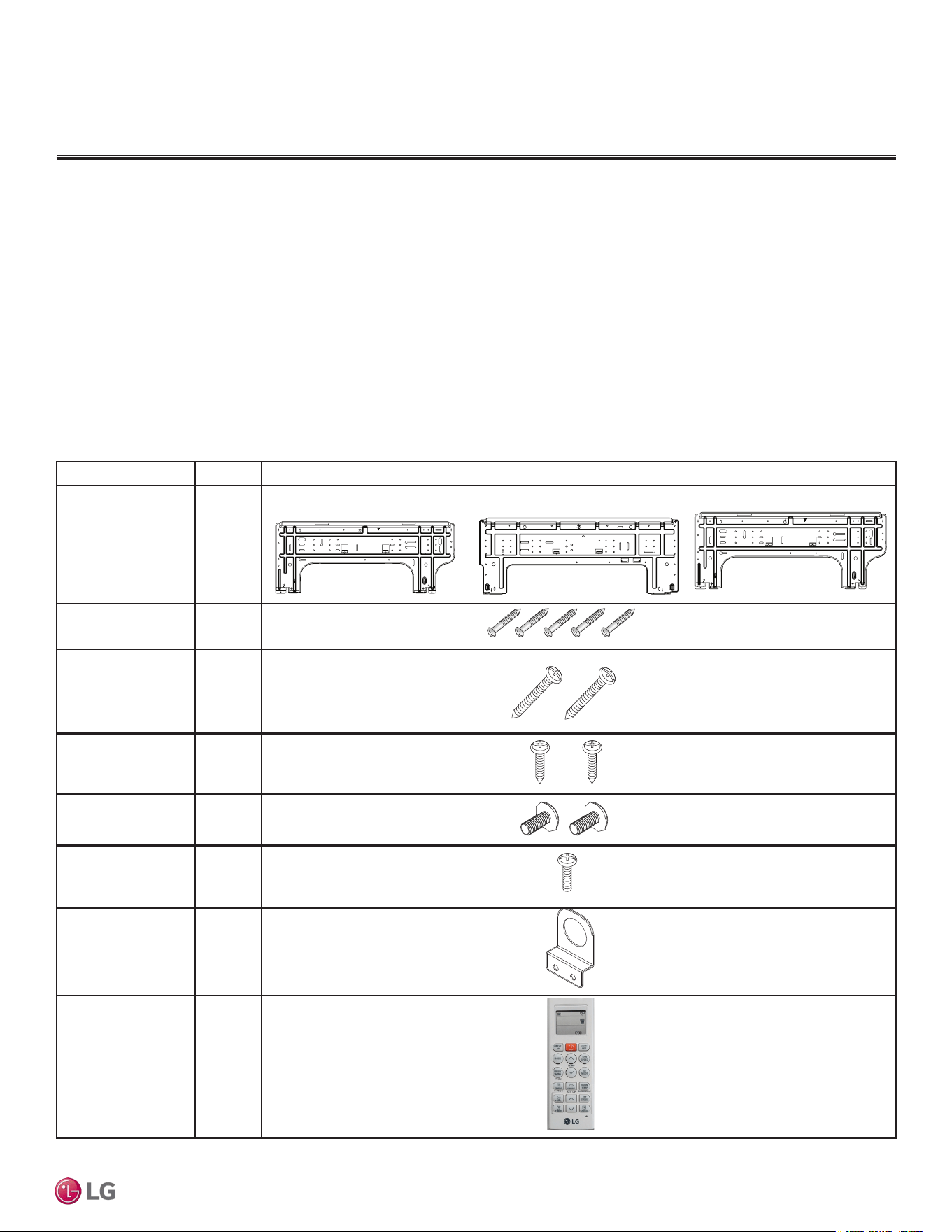
Parts
Part Quantity Image
Installation Plate One (1)
Type “A” Screws Five (5)
Type “B” Screws Two (2)
Type “C” Screws Two (2)
Type “D” Screws Two (2)
Type “E” Screws One (1)
Bracket One (1)
Wireless
Controller with Holder
One (1)
• Connecting cable (power and control)
• Pipes - vapor line and liquid line, with insulation
• Insulated drain hose
• Additional drain hose
• Level
• Screwdriver
• Electrical lineman pliers
• Electric drill
• Hole saw
• Drill
• Flaring tool set
• Tubing cutter
• Tube/pipe reamer
• Torque wrenches
• Allen wrench
• Gas-leak detector
• Thermometer
• Measuring tape
• Multimeter
• Ammeter
Required Tools (field provided)
Required Parts (field provided)
Included Parts (Depends on Model)
Mega 115V 9,000 and 12,000
Mega, Standard Efficiency
9,000 and 12,000
Mega, Standard Efficiency
18,000 and 24,000

10
Single Zone Mega, Standard Eciency, and Mega 115V Wall Mounted Installation Manual
Due to our policy of continuous product innovation, some specifications may change without notification.
©LG Electronics U.S.A., Inc., Englewood Cliffs, NJ. All rights reserved. “LG” is a registered trademark of LG Corp.
GENERAL DATA
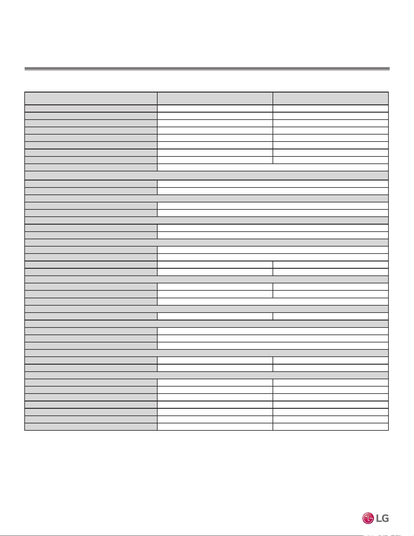
Table 1: Single Zone Mega System Specications.
Specications
System Model Number (IDU/ODU)
LS090HEV2
(LSN090HEV2/
LSU090HEV2)
LS120HEV2
(LSN120HEV2/
LSU120HEV2)
LS180HEV2
(LSN180HEV2/
LSU180HEV2)
LS240HEV2
(LSN240HEV2/
LSU240HEV2)
Cooling Capacity (Min/Rated/Max) (Btu/h) 3,070 ~ 9,000 ~10,330 3,070 ~ 12,000 ~ 13,780 3,685 ~ 18,000 ~ 18,493 3,685 ~ 22,000 ~ 24,000
Cooling Power Input
1
(kW) 0.72 1.142 1.5 2.0
Heating Capacity (Min/Rated/Max) (Btu/h) 3,070 ~ 10,900 ~ 12,520 3,070 ~ 12,000 ~ 13,780 3,685 ~ 19,000 ~ 22,997 3,685 ~ 22,000 ~25,260
Heating Power Input
1
(kW) 0.875 1.000 1.583 1.93
COP 12.46 12.00 12.00 11.40
Max. Heating Capacity (Btu/h)
Outdoor 17°F (WB)/Indoor 70°F (DB)
8,760 (80%) 9,640 (80%) 15,270 (80%) 17,680 (80%)
EER 12.5 10.51 12.00 11.00
SEER 20.0 19.0 19.0 19.0
HSPF 10.0 9.5 10.0 9.5
Power Supply (V/Hz/Ø) 208-230/60/1
Outdoor Unit Operating Range
Cooling (°F DB) 14 to 118
Heating (°F WB) 14 to 65
Indoor Unit Operating Range
Cooling (°F WB) 53 to 75
Heating (°F DB) 60 to 86
Indoor Temperature Setting Range
Cooling (°F) 64 to 86
Heating (°F) 60 to 86
Unit Data
Refrigerant Type
2
R410A
Refrigerant Control EEV
IDU Sound Pressure
3
dB(A) (H/M/L/Sleep) 42 / 36 / 28 / 21 42 / 36 / 28 / 21 48 / 43 / 38 / 32 48 / 43 / 38 / 32
ODU Sound Pressure
3
dB(A) 50 50 55 55
Unit Weight (lbs)
IDU (Net / Shipping) 19.2 / 25.4 19.2 / 25.4 26 / 30 26 / 30
ODU (Net / Shipping) 55.3 / 60 55.3 / 60 98.1 / 108 98.1 / 108
Power/Communication Cable
4
(No. x AWG) 4 x 14
Compressor
Compressor Type (Qty) Twin Rotary (1)
Fan
Indoor Unit Type (Qty) Cross Flow (1)
Outdoor Unit Type (Qty) Propeller (1)
Motor/Drive Brushless Digital Controlled/Direct
Airflow Rate
Indoor Unit Max/H/M/L (CFM) 459 / 353 / 264 / 148 459 / 353 / 264 / 148 689 / 512 / 459 / 371 689 / 512 / 459 / 371
Outdoor Unit (Max. [CFM]) 953 953 1,730 1,730
Piping
Liquid Line (in, OD) 1/4 1/4 1/4 1/4
Vapor Line (in, OD) 3/8 3/8 1/2 1/2
Condensation Line (OD, ID) 27/32, 5/8 27/32, 5/8 27/32, 5/8 27/32, 5/8
Additional Refrigerant Charge (oz/ft) 0.22 0.22 0.26 0.26
Pipe Length
5
(Minimum/Maximum)(ft) 9.8 / 49.2 9.8 / 49.2 9.8 / 65.6 9.8 / 65.6
Piping Length
5
(no add’l refrigerant, ft) 24.6 24.6 24.6 24.6
Max Elevation Difference (ft) 23 23 32.8 32.8
EEV: Electronic Expansion Valve IDU: Indoor Unit ODU: Outdoor Unit
This unit comes with a dry helium charge.
This data is rated 0 ft above sea level with 24.6 of refrigerant line per indoor unit and a 0 ft level
difference outdoor and indoor units.
Cooling capacity rating obtained with air entering the indoor unit at 80ºF dry bulb (DB) and 67ºF wet
bulb (WB) and outdoor ambient conditions of 95ºF dry bulb (DB) and 75ºF wet bulb (WB).
Heating capacity rating obtained with air entering the indoor unit at 70ºF dry bulb (DB) and 59ºF wet
bulb (WB) and outdoor ambient conditions of 47ºF dry bulb (DB) and 43ºF wet bulb (WB).
1
Power Input is rated at high speed.
2
Take appropriate actions at the end of HVAC equipment life to recover, recycle, reclaim or destroy R410A
refrigerant according to applicable regulations (40 CFR Part 82, Subpart F) under section 608 of CAA.
3
Sound Pressure levels are tested in an anechoic chamber under ISO Standard 3745.
4
All communication / connection (power) cable from the outdoor unit to the indoor unit is field supplied
and must be a minimum of four-conductor, 14 AWG, stranded, shielded or unshielded (if shielded, it
must be grounded to the chassis of the outdoor unit only), and must comply with applicable local and
national codes. For detailed electrical information, please see the Electrical Data section.
5
Piping lengths are equivalent.

11
Product Data
Due to our policy of continuous product innovation, some specifications may change without notification.
©LG Electronics U.S.A., Inc., Englewood Cliffs, NJ. All rights reserved. “LG” is a registered trademark of LG Corp.
GENERAL DATA
Table 2: Single Zone Standard Efciency System Specications.
System Model Number (IDU/ODU)
LS090HFV3
(LSN090HFV3 /
LSU090HFV3)
LS120HFV3
(LSN120HFV3 /
LSU120HFV3)
LS180HFV3
(LSN180HFV3 /
LSU180HFV3)
LS240HFV3
(LSN240HFV3 /
LSU240HFV3)
Cooling Capacity (Min/Rated/Max) (Btu/h)
3,070 ~ 9,000 ~10,330 3,070 ~ 12,000 ~ 13,780 3,685 ~ 18,000 ~ 18,493 3,685 ~ 22,000 ~ 24,000
Cooling Power Input
1
(kW)
0.82 1.25 1.65 2.2
Heating Capacity (Min/Rated/Max) (Btu/h)
3,070 ~ 10,900 ~ 12,520 3,070 ~ 12,000 ~ 13,780 3,685 ~ 19,000 ~ 22,997 3,685 ~ 22,000 ~25,260
Heating Power Input
1
(kW)
0.95 1.05 1.74 2.02
COP
11.47 11.43 10.92 10.86
Max. Heating Capacity (Btu/h)
Outdoor 17°F (WB)/Indoor 70°F (DB)
8,760 (80%) 9,640 (80%) 15,270 (80%) 17,680 (80%)
EER
10.98 9.60 10.91 10.00
SEER
17 17 17 17
HSPF
9.0 9.0 9.0 9.0
Power Supply (V/Hz/Ø)
208-230/60/1
Outdoor Unit Operating Range
Cooling (°F DB)
14 to 118
Heating (°F WB)
14 to 65
Indoor Unit Operating Range
Cooling (°F WB)
53 to 75
Heating (°F DB)
60 to 86
Indoor Temperature Setting Range
Cooling (°F)
64 to 86
Heating (°F)
60 to 86
Unit Data
Refrigerant Type
2
R410A
Refrigerant Control
EEV
IDU Sound Pressure
3
dB(A) (H/M/L/Sleep)
42 / 36 / 28 / 21 42 / 36 / 28 / 21 48 / 43 / 38 / 32 48 / 43 / 38 / 32
ODU Sound Pressure
3
dB(A)
50 50 55 55
Unit Weight (lbs)
IDU (Net / Shipping)
19.2 / 25.4 19.2 / 25.4 26 / 30 26 / 30
ODU (Net / Shipping)
55.3 / 60 55.3 / 60 98.1 / 108 98.1 / 108
Power/Communication Cable
4
(No. x AWG)
4 x 14
Compressor
Compressor Type (Qty)
Twin Rotary (1)
Fan
Indoor Unit Type (Qty)
Cross Flow (1)
Outdoor Unit Type (Qty)
Propeller (1)
Motor/Drive
Brushless Digital Controlled/Direct
Airflow Rate
Indoor Unit Max/H/M/L (CFM)
459 / 353 / 264 / 148 459 / 353 / 264 / 148 689 / 512 / 459 / 371 689 / 512 / 459 / 371
Outdoor Unit (Max. [CFM])
953 953 1,730 1,730
Piping
Liquid Line (in, OD)
1/4 1/4 1/4 1/4
Vapor Line (in, OD)
3/8 3/8 1/2 1/2
Condensation Line (OD, ID)
27/32, 5/8 27/32, 5/8 27/32, 5/8 27/32, 5/8
Additional Refrigerant Charge (oz/ft)
0.22 0.22 0.26 0.26
Pipe Length
5
(Minimum/Maximum)(ft)
9.8 / 49.2 9.8 / 49.2 9.8 / 65.6 9.8 / 65.6
Piping Length
5
(no add’l refrigerant, ft)
24.6 24.6 24.6 24.6
Max Elevation Difference (ft)
23 23 32.8 32.8
EEV: Electronic Expansion Valve IDU: Indoor Unit ODU: Outdoor Unit
This unit comes with a dry helium charge.
This data is rated 0 ft above sea level with 24.6 of refrigerant line per indoor unit and a 0 ft level
difference outdoor and indoor units.
Cooling capacity rating obtained with air entering the indoor unit at 80ºF dry bulb (DB) and 67ºF wet
bulb (WB) and outdoor ambient conditions of 95ºF dry bulb (DB) and 75ºF wet bulb (WB).
Heating capacity rating obtained with air entering the indoor unit at 70ºF dry bulb (DB) and 59ºF wet
bulb (WB) and outdoor ambient conditions of 47ºF dry bulb (DB) and 43ºF wet bulb (WB).
1
Power Input is rated at high speed.
2
Take appropriate actions at the end of HVAC equipment life to recover, recycle, reclaim or destroy R410A
refrigerant according to applicable regulations (40 CFR Part 82, Subpart F) under section 608 of CAA.
3
Sound Pressure levels are tested in an anechoic chamber under ISO Standard 3745.
4
All communication / connection (power) cable from the outdoor unit to the indoor unit is field supplied
and must be a minimum of four-conductor, 14 AWG, stranded, shielded or unshielded (if shielded, it
must be grounded to the chassis of the outdoor unit only), and must comply with applicable local and
national codes. For detailed electrical information, please see the Electrical Data section.
5
Piping lengths are equivalent.
Specications
12
Single Zone Mega, Standard Eciency, and Mega 115V Wall Mounted Installation Manual
Due to our policy of continuous product innovation, some specifications may change without notification.
©LG Electronics U.S.A., Inc., Englewood Cliffs, NJ. All rights reserved. “LG” is a registered trademark of LG Corp.
GENERAL DATA
Specications
Table 3: Single Zone Mega 115V System Specications.
EEV: Electronic Expansion Valve IDU: Indoor Unit ODU: Outdoor Unit
This unit comes with a dry helium charge.
This data is rated 0 ft above sea level with 24.6 of refrigerant line per indoor unit and a 0 ft level
difference outdoor and indoor units.
Cooling capacity rating obtained with air entering the indoor unit at 80ºF dry bulb (DB) and 67ºF wet
bulb (WB) and outdoor ambient conditions of 95ºF dry bulb (DB) and 75ºF wet bulb (WB).
Heating capacity rating obtained with air entering the indoor unit at 70ºF dry bulb (DB) and 59ºF wet
bulb (WB) and outdoor ambient conditions of 47ºF dry bulb (DB) and 43ºF wet bulb (WB).
1
Power Input is rated at high speed.
2
Take appropriate actions at the end of HVAC equipment life to recover, recycle, reclaim or destroy R410A
refrigerant according to applicable regulations (40 CFR Part 82, Subpart F) under section 608 of CAA.
3
Sound Pressure levels are tested in an anechoic chamber under ISO Standard 3745.
4
All communication / connection (power) cable from the outdoor unit to the indoor unit is field supplied
and must be a minimum of four-conductor, 14 AWG, stranded, shielded or unshielded (if shielded, it
must be grounded to the chassis of the outdoor unit only), and must comply with applicable local and
national codes. For detailed electrical information, please see the Electrical Data section.
5
Piping lengths are equivalent.
System Model Number (IDU/ODU) LS090HXV2 (LSN090HXV2/LSU090HXV2) LS120HXV2 (LSN120HXV2/LSU120HXV2)
Cooling Capacity (Min/Rated/Max) (Btu/h) 3,070 ~ 9,000 ~ 10,330 3,070 ~ 12,000 ~ 13,780
Cooling Power Input
1
(kW) 0.732 1.142
Heating Capacity (Min/Rated/Max) (Btu/h) 3,070 ~ 10,900 ~ 12,520 3,070 ~ 12,000 ~ 13,780
Heating Power Input
1
(kW) 0.875 1.000
COP 3.65 3.52
EER 12.30 10.51
SEER 20 19
HSPF 10 9.5
Power Supply (V/Hz/Ø) 115/60/1
Outdoor Unit Operating Range
Cooling (°F DB) 14 to 118
Heating (°F WB) 14 to 65
Indoor Unit Operating Range
Cooling (°F WB) 53 to 75
Heating (°F DB) 60 to 86
Indoor Temperature Setting Range
Cooling (°F) 65 to 86
Heating (°F) 60 to 86
Unit Data
Refrigerant Type
2
R410A
Refrigerant Control EEV
IDU Sound Pressure
3
dB(A) (H/M/L/Sleep) 42 / 36 / 28 / 21 42 / 36 / 28 / 21
ODU Sound Pressure
3
dB(A) 50 50
Unit Weight (lbs)
IDU (Net/Shipping) 19.2 / 22 19.2 / 22
ODU (Net/Shipping) 58.4 / 60 58.4 / 60
Power/Communication Cable
4
(No. x AWG) 4 x 14
Compressor
Compressor Type (Qty) Twin Rotary (1) Twin Rotary (1)
Fan
IDU Type (Qty) Cross Flow (1)
ODU Type (Qty) Propeller (1)
Motor/Drive Brushless Digitally Controlled/Direct
Airflow Rate
IDU Max/H/M/L (CFM) 459 / 353 / 264 / 148 459 / 353 / 264 / 148
ODU Max (CFM) 953 953
Piping
Liquid Line (in, OD) 1/4 1/4
Vapor Line (in, OD) 3/8 3/8
Condensation Line (OD, ID) 27/32, 5/8 27/32, 5/8
Additional Refrigerant Charge (oz/ft) 0.22 0.22
Pipe Length
5
(Minimum/Maximum)(ft) 9.8 / 49.2 9.8 / 49.2
Piping Length
5
(no add’l refrigerant, ft) 24.6 24.6
Max Elevation Difference (ft) 23 23

13
Product Data
Due to our policy of continuous product innovation, some specifications may change without notification.
©LG Electronics U.S.A., Inc., Englewood Cliffs, NJ. All rights reserved. “LG” is a registered trademark of LG Corp.
GENERAL DATA
Electrical
Table 4: 115V, 60Hz, 1-Phase Single Zone Mega 115V System Electrical Data Table.
Voltage tolerance is ±10%.
Maximum allowable voltage unbalance is 2%.
MCA = Minimum Circuit Ampacity.
Maximum Overcurrent Protection (MOP) is calculated as follows: (Largest motor FLA x 2.25) + (Sum of
other motor FLA) rounded down to the nearest standard fuse size.
RLA = Rated Load Amps.
FLA = Full Load Amps.
Nominal
Tons
Unit Model
No.
Hertz Voltage
Voltage
Range (Min.
to Max.)
MCA MOP
Compressor
Quantity
Compressor Motor
RLA
Outdoor Fan
Motor
Indoor Fan
Motor
Cooling Heating W FLA W FLA
3/4 LS090HXV2
60 115 98-132
15 25 1 11.0 11.0 43 0.4 30 0.4
1 LS120HXV2 15 25 1 11.0 11.0 43 0.4 30 0.4
Nominal
Tons
Unit Model
No.
Hertz Voltage
Voltage
Range (Min.
to Max.)
MCA MOP
Compressor
Quantity
Compressor
Motor RLA
Outdoor Fan
Motor
Indoor Fan
Motor
Cooling Heating W FLA W FLA
3/4 LS090HEV2
60 208 - 230 187-253
10.0 15 1 7.0 7.0 43 0.4 30 0.4
1 LS120HEV2 10.0 15 1 7.0 7.0 43 0.4 30 0.4
1-1/2 LS180HEV2 15.0 20 1 10.0 10.0 85 0.4 58 0.4
2 LS240HEV2 15.0 20 1 10.0 10.0 85 0.4 58 0.4
3/4 LS090HFV3 10.0 15 1 7.0 7.0 43 0.4 30 0.4
1 LS120HFV3 10.0 15 1 7.0 7.0 43 0.4 30 0.4
1-1/2 LS180HFV3 15.0 20 1 10.0 10.0 85 0.4 58 0.4
2 LS240HFV3 15.0 20 1 10.0 10.0 85 0.4 58 0.4
Table 5: 208-230V, 60Hz, 1-Phase Single Zone Mega, Standard Efciency System Electrical Data Table.
Electrical Data for Mega, Standard Efficiency Models
Electrical Data for Mega 115V Models

14
Single Zone Mega, Standard Eciency, and Mega 115V Wall Mounted Installation Manual
Due to our policy of continuous product innovation, some specifications may change without notification.
©LG Electronics U.S.A., Inc., Englewood Cliffs, NJ. All rights reserved. “LG” is a registered trademark of LG Corp.
GENERAL INSTALLATION GUIDELINES
Selecting the Best Location for the Outdoor Unit
DANGER
• Do not install the unit in an area where combustible gas will generate, flow, stagnate, or leak. These conditions can cause a fire, resulting
in bodily injury or death.
• Do not install the unit in a location where acidic solution and spray (sulfur) are often used as it can cause bodily injury or death.
• Do not use the unit in environments where oil, steam, or sulfuric gas are present as it can cause bodily injury or death.
When deciding on a location to place the outdoor unit, be sure to choose an area where run-off water from defrost cycle will not accumulate and freeze
on sidewalks or driveways, which will create unsafe conditions. Properly install and insulate any drain hoses to prevent the hose from freezing, crack-
ing, leaking, and causing unsafe conditions from frozen condensate.
Install a fence to prevent vermin from crawling into the unit or unauthorized individuals from accessing it. Vermin and unauthorized individuals will cause
a re, electric shock, physical injury or death. Follow the placement guidelines set forth in “Clearance Requirements”.
Install a fence to prevent vermin from crawling into the unit or unauthorized individuals from accessing it. Vermin and unauthorized individuals will
damage the unit. Follow the placement guidelines set forth in “Clearance Requirements”.
Select a location for installing the outdoor unit that will meet the following conditions:
• Where there is enough structural strength to bear the weight of the unit.
• A location that allows for optimum air flow and is easily accessible for inspection, maintenance, and service.
• Where piping between the outdoor unit and indoor unit is within allowable limits.
• Include space for drainage to ensure condensate flows properly out of the unit when it is in heating mode.
Avoid placing the outdoor
unit in a low-lying area where water could accumulate.
• If the outdoor unit is installed in a highly humid environment (near an ocean, lake, etc.), ensure that the site is well-ventilated and has a lot
of natural light (Example: Install on a rooftop).
Do Not’s
• Where it will be subjected to direct thermal radiation from other heat sources, or an area that would expose the outdoor unit to heat or steam
like discharge from boiler stacks, chimneys, steam relief ports, other air conditioning units, kitchen vents, plumbing vents, and other sources
of extreme temperatures.
• Where high-frequency electrical noise / electromagnetic waves will affect operation.
• Where operating sound from the unit will disturb inhabitants of surrounding buildings.
• Where the unit will be exposed to direct, strong winds.
• Where the discharge of one outdoor unit will blow into the inlet side of an adjacent unit (when installing multiple outdoor units).
Planning for Snow and Ice
To ensure the outdoor unit operates properly, certain measures are required in locations where there is a possibility of heavy snowfall or
severe windchill or cold:
1. Prepare for severe winter wind chills and heavy snowfall, even in areas of the country where these are unusual phenomena.
2. Position the outdoor unit so that its airflow fans are not buried by direct, heavy snowfall. If snow piles up and blocks the airflow, the sys-
tem will malfunction.
3. Remove any snow that has accumulated four (4) inches or more on the top of the outdoor unit.
4. In climates that can experience significant snow buildup, mount the outdoor unit on a raised, field-provided platform or stand. The raised
support platform must be high enough to allow the unit to remain above possible snow drifts, and must be higher than the maximum antici-
pated snowfall for the location.
5. Design the mounting base to prevent snow accumulation on the platform in front or back of the unit frame.
6. Provide a field fabricated snow protection hood to keep snow and ice and/or drifting snow from accumulating on the coil surfaces.
7. To prevent snow and heavy rain from entering the outdoor unit, install the condenser air inlets and outlets facing away from direct
winds.
8. Consider tie-down requirements in case of high winds or where required by local codes.
Outdoor Unit Location Selection

15
General Installation Guidelines
Due to our policy of continuous product innovation, some specifications may change without notification.
©LG Electronics U.S.A., Inc., Englewood Cliffs, NJ. All rights reserved. “LG” is a registered trademark of LG Corp.
GENERAL INSTALLATION GUIDELINES
Planning for Snow and Ice, continued.
The indoor unit will take longer to provide heat, or heating performance will be reduced in winter if the unit is installed:
Choose an area where run-off water from defrost cycle will not accumulate and freeze on sidewalks or driveways. Properly install and insulate any drain
hoses to prevent the hose from freezing, cracking, leaking, and damaging the outdoor unit.
1. In a narrow, shady location.
2. Near a location that has a lot of ground moisture.
3. In a highly humid environment.
4. In an area in which condensate does not drain properly.
Outdoor Unit Location Selection
When deciding on a location to place the outdoor unit, be sure to choose an area where run-off water from defrost cycle will not accumulate and freeze
on sidewalks or driveways, which will create unsafe conditions. Properly install and insulate any drain hoses to prevent the hose from freezing, crack-
ing, leaking, and causing unsafe conditions from frozen condensate.
Tie-Downs and Lightning Protection
Tie-Downs
• The strength of the roof must be checked before installing the
outdoor units.
• If the installation site is prone to high winds or earthquakes, when
installing on the wall or roof, securely anchor the mounting base
using a field-provided tie-down configuration approved by a local
professional engineer.
• The overall tie-down configuration must be approved by a local
professional engineer.
Always refer to local code when using a wind restraint system.
Lightning Protection
• To protect the outdoor unit from lightning, it must be placed within
the specified lightning safety zone.
• Power cable and communication cable must be installed five (5) feet away from lightning rod.
• A high-resistance ground system must be included to protect against induced lightning or indirect strike.
Building Height (feet) 66 98 148 197
Protection Angle (˚) 55 45 35 25
If the building does not include lightning protection, the outdoor unit will be damaged from a lightning strike. Inform the customer of this possibility in
advance.
Ground
Safe zone
Lightning rod
Protection Angle (25˚~55˚)
5 feet
Lightning rod
Figure 1: Lightning Protection Diagram.
Table 6: Safety Zone Specifications.

16
Single Zone Mega, Standard Eciency, and Mega 115V Wall Mounted Installation Manual
Due to our policy of continuous product innovation, some specifications may change without notification.
©LG Electronics U.S.A., Inc., Englewood Cliffs, NJ. All rights reserved. “LG” is a registered trademark of LG Corp.
GENERAL INSTALLATION GUIDELINES
• Avoid installing the outdoor unit where it would be directly
exposed to ocean winds.
• Install the outdoor unit on the side of the building opposite from
direct ocean winds.
• Select a location with good drainage.
• Periodically clean dust or salt particles off of the heat exchanger
with water.
• If the outdoor unit must be placed in a location where it would
be subjected to direct ocean winds, install a concrete windbreak
strong enough to block any winds.
• Windbreak must be more than 150% of the outdoor unit’s height.
There must be 2 to 3-1/2 inches of clearance between the outdoor
unit and the windbreaker for purposes of air flow.
Additional anti-corrosion treatment will need to be applied to the outdoor
unit at oceanside locations.
Ocean winds will cause corrosion, particularly on the condenser and
evaporator ns, which, in turn could cause product malfunction or inef-
cient performance.
Oceanside Applications
Use of a Windbreak to Shield from Sea Wind
Use of a Building to Shield from Sea Wind
If a windbreak is not possible, a building or larger structure must be
used to shield the outdoor unit from direct exposure to the sea wind.
The unit must be placed on the side of the building directly opposite
to the direction of the wind as shown at right.
Figure 2: Oceanside Placement Using Windbreak.
Figure 3: Placement Using Building as Shield.
Sea wind
Windbreak
Sea wind
Sea wind
Building
Building
Outdoor Unit Location Selection

17
General Installation Guidelines
Due to our policy of continuous product innovation, some specifications may change without notification.
©LG Electronics U.S.A., Inc., Englewood Cliffs, NJ. All rights reserved. “LG” is a registered trademark of LG Corp.
GENERAL INSTALLATION GUIDELINES
Required Outdoor Unit Clearances
Mega, Standard Efficiency, and Mega 115V Outdoor Unit Service Access and Allowable Clearances
Specific clearance requirements in the diagram below are for all outdoor units. The figure below shows the overall minimum clearances that
must be observed for safe operation and adequate airflow around the outdoor unit.
When placing the outdoor unit under an overhang, awning, sunroof or other “roof-like structure”, observe the clearance requirements (as
shown in Cases 1 and 2) for height in relation to the unit. To have successful service access to the outdoor unit, see the figure below for
minimum spacing. When installing multiple outdoor units, see Cases 4 and 5 for correct spacing requirements.
Figure 4: Single Zone Mega, Standard Efciency, and Mega 115V Outdoor Unit Service Access and Allowable Clearances Diagram.
Unit: Inch A B C D E F G
Case 1
Standard 12 24 - 12 - - -
Minimum 4 10 - 4 - - 40
Case 2
Standard - - 20 - - - -
Minimum - - 14 - - - 40
Case 3
Standard - - 20 12 - - -
Minimum - - 14 4 - - -
Case 4
Standard - - - 12 24 - -
Minimum - - - 4 8 79 -
Case 5
Standard - 24 - 12 - - -
Minimum - 10 - 4 - - -
Table 7: Single Zone Mega, Standard Efciency, and Mega 115V Outdoor Unit Service Access and Allowable Clearances Diagram Legend.
Do not place the unit where animals
and/or plants will be in the path of the
warm air, or where the warm air and/or
noise will disturb neighbors.
If the outdoor unit is installed between standard and minimum clearances, capacity decreases approximately 10%.
Minimum Allowable Clearance and Service Access Requirements
Proper clearance for the outdoor unit coil is critical for proper operation. When installing the outdoor unit, consider service, inlet and outlet,
and minimum allowable space requirements as illustrated in the diagrams below.
• Include enough space for airflow and for service access. If installing multiple outdoor units,
avoid placing the units where the discharge
of one unit will blow into the inlet side of an adjacent unit.
• If an awning is built over the unit to prevent direct sunlight or rain exposure, make sure that the discharge air of the outdoor unit isn’t restricted.
•
No obstacles to air circulation around the unit; keep proper distances from ceilings, fences, floor, walls, etc. (Install a fence to prevent
pests from damaging the unit or unauthorized individuals from accessing it.)
A
B
D
G
C
G
C
D
E
D
D
B
B
F
1/16 inch
20 inches or less
Case 1
Case 4
Case 2 Case 3
Case 5
20 inches or less

18
Single Zone Mega, Standard Eciency, and Mega 115V Wall Mounted Installation Manual
Due to our policy of continuous product innovation, some specifications may change without notification.
©LG Electronics U.S.A., Inc., Englewood Cliffs, NJ. All rights reserved. “LG” is a registered trademark of LG Corp.
GENERAL INSTALLATION GUIDELINES
Rigging and Lifting / Outdoor Unit Mounting
Rigging and Lifting Instructions
Wear protective gloves and safety goggles when handling equipment. Sharp edges will cause personal injury.
Dispose of the packing materials safely.
• Packing materials, such as nails and other metal or wooden parts, will cause puncture wounds or other injuries.
• Tear apart and throw away plastic packaging bags so that children do not play with them and risk suffocation and death.
• Be very careful when transporting the product. There is a risk of the product falling and causing physical injury.
• Use appropriate moving equipment to transport each frame; ensure the equipment is capable of supporting the weights listed.
• Some products use polypropylene bands for packaging. Do not use polypropylene bands to lift the unit.
• Support the outdoor unit at a minimum of four points to avoid slippage from rigging apparatus.
• Make sure the outdoor unit is in its original packaging to avoid damage during local transport.
• At the time of delivery, the package must be checked for any damage (exterior and interior). Report any damage to the carrier claims agent
immediately.
• Handle the outdoor unit with care. Keep the outdoor unit upright to avoid damaging inside components.
• If a forklift is to transport the outdoor unit, the forklift arms must pass through the openings at the bottom.
• If a crane is to suspend the outdoor unit, it is required that two (2) ropes at least twenty-three (23) feet in length be used. Pass the ropes under
the unit. Pass the rope through the two (2) forklift slots each at the front and rear of the outdoor unit.
• To prevent damage to the outdoor unit, always lift the unit with the ropes attached at four (4) points at an angle of ≤40°.
• Always include padding to protect the outdoor unit from rope damage, and take into consideration the outdoor unit’s center of gravity.
General Outdoor Unit Mounting
Any underlying structure or foundation must be designed to support
the weight of the outdoor unit. Avoid placing the unit in a low
lying area where water and ice will accumulate. Securely attach the
outdoor unit to a condenser pad, base rails, or a mounting platform
that is solidly anchored to the ground or building structure. When
installing the outdoor unit on the wall or roof top, securely anchor the
mounting base to account for wind, earthquakes, or vibration.
Anchoring the Outdoor Unit
• Tightly anchor the outdoor unit with a bolt and nut to a concrete or
rigid platform (see next page for more details).
• When installing on a wall (with field-supplied brackets), roof, or
rooftop, securely anchor the mounting platform with nails, taking
into consideration the possibility of strong winds or earthquakes.
• If there is a possibility of vibration from the outdoor unit transmit-
ting to the building, add an anti-vibration material.
Follow applicable local codes for clearance, mounting, anchor and vibration attenuation requirements.
Figure 5: Examples of Outdoor Unit Mounting Methods.

19
General Installation Guidelines
Due to our policy of continuous product innovation, some specifications may change without notification.
©LG Electronics U.S.A., Inc., Englewood Cliffs, NJ. All rights reserved. “LG” is a registered trademark of LG Corp.
GENERAL INSTALLATION GUIDELINES
Model
Foundation (Inches) Leg
Thickness
(Inches)
A B C
LSU090HEV2,
LSU120HEV2,
LSU090HFV3,
LSU120HFV3;
LSU090HXV2,
LSU120HXV2
18-7/32 Minimum 4 11-1/32 1/16
LSU180HEV2,
LSU180HFV3,
LSU240HEV2,
LSU240HFV3
23-1/16 Minimum 4 15-3/4 1/16
Concrete Platform Specifications
• Concrete foundations must be made of one part cement, two parts sand, and four parts gravel.
• The surface of the foundation must be finished with mortar with rounded edges, and weatherproofed.
All referenced materials are to be eld-supplied. Images are not to scale.
B
A
C
M10
Anchor Bolt
Min. 3 to 5 inches
Min. 1
inches
Bolt
Placement
& Anti-Vibration
Pad
Piping Connection
Top of Unit
Foundation
Bolting the Outdoor Unit to the Platform
1. Ensure that the concrete platform will not degrade easily, and
has enough structural strength to bear the weight of the unit.
2. Include an H-beam support. Firmly attach the corners, otherwise
the support will bend.
3. Use a hexagon nut.
4. Use anti-vibration material.
5. Include enough space around the concrete foundation for con-
densate drainage.
6. Seal all wiring and piping access holes to prevent insects from
entering the unit.
Figure 6: Example of Using an Insert for a Hole
in a Reinforced Concrete Beam.
Outdoor Unit Platform Dimensional Requirements
Figure 7: Close up of Bolt Attachment.
Figure 8: Single Zone Mega, Standard Efciency, and Mega 115V Wall
Mount Outdoor Units (Appearances Will Vary Depending on Model).
Table 8: Mega , Standard Efciency, and Mega 115V Outdoor Unit
Foundation Specications.
Figure 9: Bolting the Outdoor Unit to the Platform (Piping Location Will
Differ Depending on Outdoor Unit Model).
Concrete Beam
Insert
Suspension Bolt
Polyblock /
Anti-Vibration
Material
Nail Securing
Polyblock
Outdoor Unit Mounting
Review the specications for eld-supplied pad mounts or brackets to ver-
ify that outdoor dimension requirements are met.

20
Single Zone Mega, Standard Eciency, and Mega 115V Wall Mounted Installation Manual
Due to our policy of continuous product innovation, some specifications may change without notification.
©LG Electronics U.S.A., Inc., Englewood Cliffs, NJ. All rights reserved. “LG” is a registered trademark of LG Corp.
GENERAL INSTALLATION GUIDELINES
Selecting the Best Location for the Indoor Unit
Follow recommended best practices when choosing an indoor location for the single
zone indoor unit.
Dos
• Follow the table at right for minimum clearance of indoor unit from the top of
the unit to the ceiling.
• Clearance gap between any wall or enclosure and the left or right side of the
unit must be greater than 4 inches. Ensure there is sufficient maintenance
space.
• Unit must be at least 6-1/2 feet from the floor for adequate clearance.
• Place the unit where drainage can be obtained easily. Condensation drain
must be conveniently routed away from the unit.
• Locate the indoor unit in a location where it can be easily connected to the
outdoor unit within allowable limits.
• Use a metal detector to locate studs in the walls. Anchor unit following stud
location to prevent damage to the wall.
Do Not’s
• Do not install the unit near a heat or steam source, or where considerable
amounts of oil, iron powder, or flour are used. (These materials will generate condensate, cause a reduction in heat exchanger efficiency, or
the drain to malfunction. If this is a potential problem, install a ventilation fan large enough to vent out these materials.)
• Ensure there are no obstacles to air circulation around the unit; keep proper distances from ceilings, doorways, floor, walls, etc.
• Do not install in an area where operation sound will disturb occupants--place the unit where noise prevention is taken into consideration
• Do not install near doorway.
• Avoid installing the unit near high-frequency generators.
Figure 10: Indoor Unit Clearance Requirements.
Ceiling Clearance (inches) Indoor Unit Model(s)
8
LSN090HEV2, LSN120HEV2,
LSN180HEV2, LSN240HEV2,
LSN090HFV3, LSN120HFV3,
LSN180HFV3, LSN240HFV3
LSN090HXV2, LSN120HXV2
Table 9: Indoor Unit Ceiling Clearance.
>4 (100)
Unit: Inch (mm)
>4 (100)
>8 (200)
At least 6-1/2 feet from the floor
The unit must not be installed where sulfuric acid and ammable or cor-
rosive gases are generated, vented into, or stored. There is risk of re,
explosion, and physical injury or death.
The unit will be damaged, will malfunction, and / or will not
operate as designed if installed in any of the conditions
listed.
• Indoor units (IDUs) must not be placed in an environment where the IDUs will be exposed to harmful volatile organic compounds (VOCs) or in
environments where there is improper air make up or supply or inadequate ventilation. If there are concerns about VOCs in the environment
where the IDUs are installed, proper air make up or supply and/ or adequate ventilation must be provided. Additionally, in buildings where
IDUs will be exposed to VOCs consider a factory-applied epoxy coating to the fan coils for each IDU.
• If the unit is installed near a body of water, the installation parts are at risk of corroding. Appropriate anti-corrosion methods must be taken for
the unit and all installation parts.
Installing in an Area Exposed to Unconditioned Air
In some installation applications, areas (floors, walls) in some rooms will be exposed to unconditioned air (room may be above or next to an
unheated garage or storeroom). To countermeasure:
• Verify that carpet is or will be installed (carpet will increase the temperature by three [3] degrees).
• Add insulation between the floor joists.
• Install radiant heat or another type of heating system to the floor.
Install a ventilation fan
with sufficient capacity
Heat or steam source
Include enough
distance
Indoor Unit
Figure 11: Installing Near a Heat or Steam Source.
Indoor Unit Location Selection / Required Indoor Unit Clearances
21
General Installation Guidelines
Due to our policy of continuous product innovation, some specifications may change without notification.
©LG Electronics U.S.A., Inc., Englewood Cliffs, NJ. All rights reserved. “LG” is a registered trademark of LG Corp.
GENERAL INSTALLATION GUIDELINES
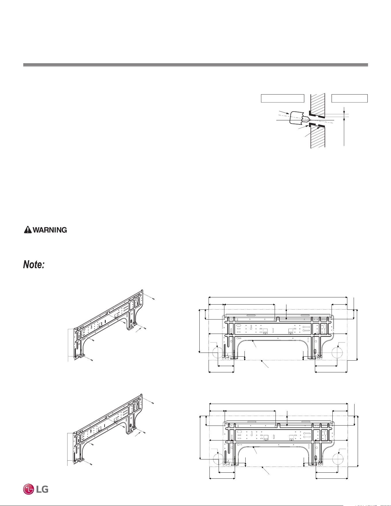
Drilling the Piping Hole in the Wall
Follow all piping clearance recommendations.
1. Using a 2-9/16 inch hole core drill bit, drill a hole at either the right or left side of the
wall mounting, pre-chosen following installation guidelines and application needs.
• The slant of the hole must be 3/16” to 5/16 inches from level with the slant being
upward on the indoor unit side and downward on the outdoor unit side.
2. Finish off the newly drilled hole as shown with bushing and sleeve covering to pre-
vent damage to the insulation and piping.
(3/16"~5/16")
Indoor
WALL
Outdoor
Bushing
Core Drill
Sleeve
Figure 14: Mega 115V Wall Mount Indoor Unit Installation Plate Dimensions.
Indoor Unit Mounting
Mounting the Installation Plate to the Wall
Follow the procedure below and general best practices when mounting the indoor unit’s installation plate to a wall.
1. Depending on the model, the wall mounted indoor unit is shipped with the installation plate attached to its back. To remove, unscrew the
one (1) screw that holds the installation plate to the back of the indoor unit.
2. Align the centerline using a leveling tool. Measure the wall and mark the centerline.
3. Attach the installation plate to the wall following the measurements and marks. Use the type “A” screws that are factory-supplied with the
plate. If mounting the unit on a concrete wall, use field-supplied anchor bolts.
4. Observe all rear piping clearances when drilling into the wall.
• When choosing a location for the wall mount plate, be sure to take into consideration routing of wiring for power outlets within the wall.
Contacting wiring can cause serious bodily injury or death.
• Use caution when drilling holes through the walls for the purposes of piping connections. Power wiring can cause serious bodily injury or death.
Select the location carefully. Unit must be anchored to a strong and solid wall to prevent unnecessary vibration.
Figure 12: Drilling Piping Hole.
Figure 13: Mega 115V Wall Mount Indoor Unit Installation Plate.
Installation Plate
32-15/16 (837)
2-15/32
(63)
12-1/16 (306)
3-21/32 (93)
10-11/32 (263)
5-31/32 (152)
3-27/32 (98)
5-9/32 (134)
12-1/8 (308)
3-11/16 (94)
7-5/8 (194)
Unit Outline
29/32 (23)
Ø2-9/16 (65)
5-19/32 (142)
Ø2-9/16 (65)
7-27/32 (199)
29/32 (23)
2-15/32 (63)
2-17/32 (64)
Figure 15: Mega, Standard Efciency 9K and 12K Wall Mount
Indoor Unit Installation Plate.
Figure 16: Mega, Standard Efciency 9K and 12K Wall Mount Indoor Unit
Installation Plate Dimensions.
Installation Plate
Chassis
Hook
Type "A" Screws
Installation Plate
Chassis
Hook
Type "A" Screws
Installation Plate
32-15/16 (837)
2-15/32
(63)
12-1/16 (306)
3-21/32 (93)
10-11/32 (263)
5-31/32 (152)
3-27/32 (98)
5-9/32 (134)
12-1/8 (308)
3-11/16 (94)
7-5/8 (194)
Unit Outline
29/32 (23)
Ø2-9/16 (65)
5-19/32 (142)
Ø2-9/16 (65)
7-27/32 (199)
29/32 (23)
2-15/32 (63)
2-17/32 (64)

22
Single Zone Mega, Standard Eciency, and Mega 115V Wall Mounted Installation Manual
Due to our policy of continuous product innovation, some specifications may change without notification.
©LG Electronics U.S.A., Inc., Englewood Cliffs, NJ. All rights reserved. “LG” is a registered trademark of LG Corp.
GENERAL INSTALLATION GUIDELINES
Installation Plate
39-9/32 (998)
2-23/32 (69)
14-11/16 (373)
5-13/32 (137)
2-3/32 (53)
13-19/32 (345)
Ø2-9/16 (65)
3-9/32 (83)
Unit Outline
1-1/16 (27)
5-29/32 (150)
4-17/32 (115)
Ø2-9/16 (65)
3-9/32 (83)
5-9/32 (134)
1-1/16 (27)
2-3/32 (53)
11-13/16 (300)
5-29/32 (150)
7-13/32 (188)
Installation Plate
Chassis
Hook
Type "A" Screws
Figure 17: Mega, Standard Efciency 18K and 24K Wall Mount
Indoor Unit Installation Plate.
Figure 18: Mega, Standard Efciency 18K and 24K Wall Mount Indoor Unit
Installation Plate Dimensions.
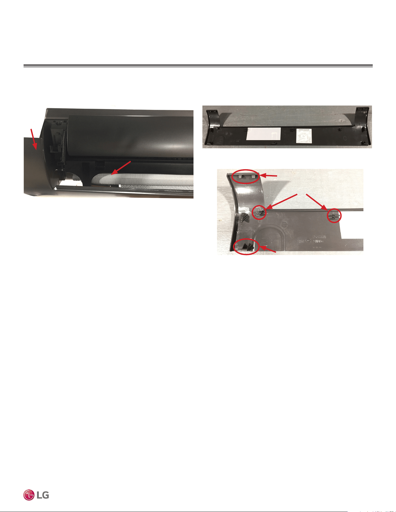
Figure 19: Indoor Unit with the Bottom Cover On (Bottom View; Appear-
ances Will Vary Depending on Indoor Unit Model).
Figure 20: Steps to Removing the
Bottom Cover.
To access the indoor unit piping port connections,
terminal block, and to make the indoor unit installation
procedure easier, it is recommended that the bottom
cover be removed first.
1. Unsnap the bottom cover at its top left and right
sides (Location 1).
2. Unsnap each of the three (3) or four (4) small
C-hooks located in the middle of the bottom cover
(Location 2). Number of C-hooks present depends
on model of indoor unit.
3. Lift the three (3) to four (4) hinges on the bottom
cover up and out of the channels molded to the
left, right, and middle of the indoor unit (Location
3). Number of hinges present depends on model
of indoor unit.
4. Set aside the bottom cover to re-install after all
procedures are complete.
3
3
3
Removing the Indoor Unit Bottom Cover (HEV2, HFV3, and HXV2 Indoor
Units)
Figure 21: Removing the Bottom Cover
(Appearances Will Vary Depending on
Indoor Unit Model).
Indoor Unit Mounting
23
General Installation Guidelines
Due to our policy of continuous product innovation, some specifications may change without notification.
©LG Electronics U.S.A., Inc., Englewood Cliffs, NJ. All rights reserved. “LG” is a registered trademark of LG Corp.
GENERAL INSTALLATION GUIDELINES
Figure 22: Back of Bottom Cover Completely Removed from Indoor Unit
(Appearances Will Vary Depending on Indoor Unit Model).
Figure 23: Bottom Cover with Top and Middle Unsnapped, Front View
(Appearances Will Vary Depending on Indoor Unit Model).
Inside of Indoor Unit
Top Left Side of
Bottom Cover
Figure 24: Close Up of Bottom Cover Connections (Appearances Will
Vary Depending on Indoor Unit Model).
Hinge
Top Snaps
C-Hooks
Removing the Indoor Unit Bottom Cover (HEV2, HFV3, and HXV2 Indoor Units), continued.
Indoor Unit Mounting
24
Single Zone Mega, Standard Eciency, and Mega 115V Wall Mounted Installation Manual
Due to our policy of continuous product innovation, some specifications may change without notification.
©LG Electronics U.S.A., Inc., Englewood Cliffs, NJ. All rights reserved. “LG” is a registered trademark of LG Corp.
GENERAL INSTALLATION GUIDELINES
The indoor unit can fall from the wall if it is not properly installed and secured to the installation plate. Falling indoor units can cause bodily injury or
death.
• To avoid a gap between the indoor unit and the wall, ensure the screws are correctly and fully secured to the installation plate.
• To prevent condensate from forming due to an inflow of outdoor air, before indoor unit installation is finished, completely seal the piping access
hole in the wall.
6. Finish the installation by completely securing the indoor unit to the installation plate using the factory-supplied two Type “C” screws at the
locations indicated.
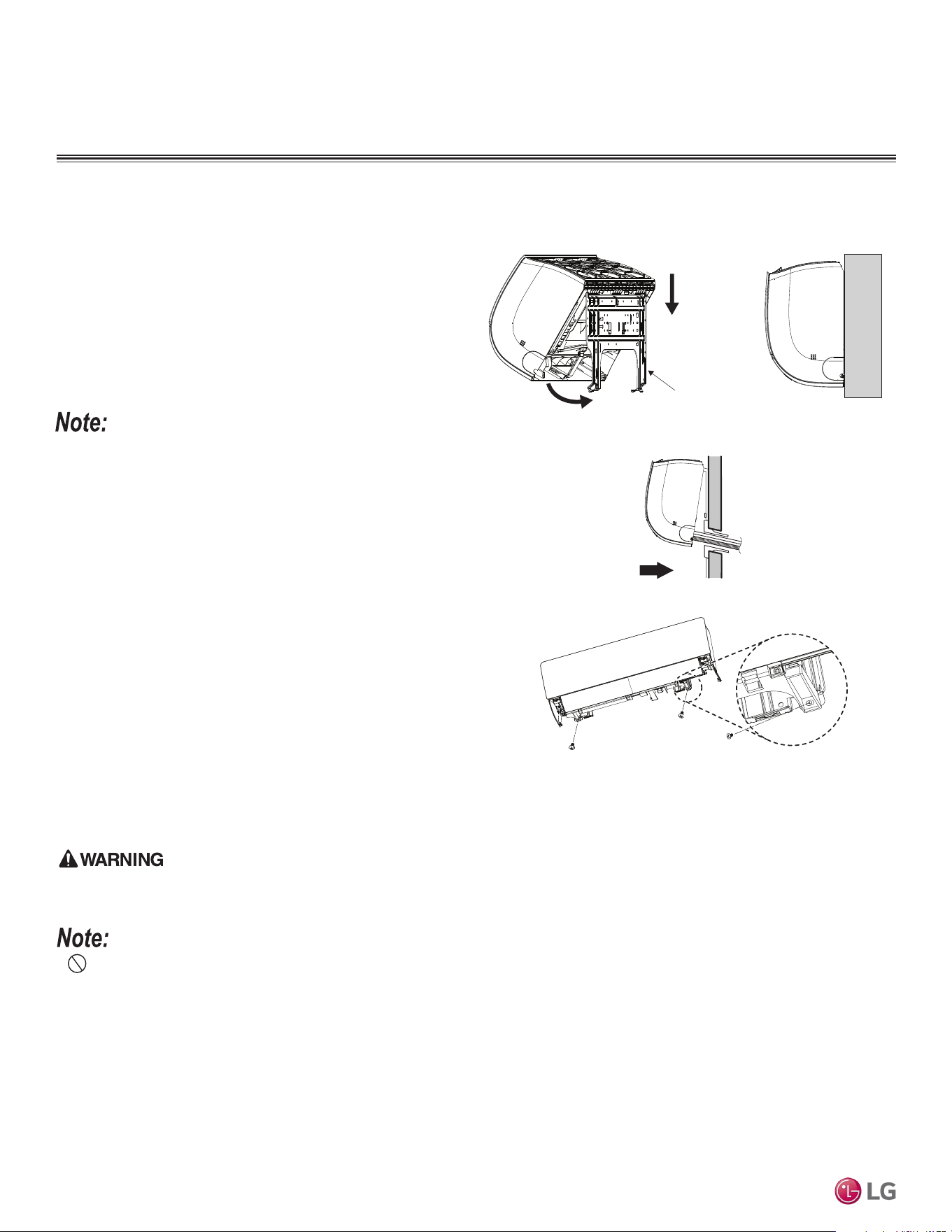
Mounting the Indoor Unit to the Installation Plate
1. Position the indoor unit onto the upper portion of the installation
plate.
2. Engage the hooks at the top of the indoor unit with the upper
edge of the installation plate (number of hooks depends on model
type).
3. Ensure the hooks are properly seated on the installation plate by
shaking the indoor unit left and right.
Permanently secure the indoor unit to the wall ONLY AFTER all other
tasks such as Refrigerant Piping Connections, Drain Piping Connections,
Electrical Connections, and Final Installation Procedures are complete.
See next page for steps on how to prepare for piping and electrical con-
nections.
4. Carefully guide the refrigerant piping and drain piping through the
access hole.
5. Push the bottom of indoor unit towards the installation plate to
anchor to the wall.
• Press the lower left and right sides of the unit against the instal-
lation plate until the hooks engage into their slots.
• A clicking sound will be heard as the bottom of the indoor unit
attaches to the installation plate successfully.
• Pay attention to the positioning of the piping through the wall.
Installation Plate
Type 'C' screw
Figure 25: Attaching the Indoor Unit to the Installation Plate
(Appearances Will Vary Depending on Model).
Figure 26: Finishing Indoor Unit Installation to the Wall Plate
(Appearances Will Vary Depending on Model).
Indoor Unit Mounting

25
General Installation Guidelines
Due to our policy of continuous product innovation, some specifications may change without notification.
©LG Electronics U.S.A., Inc., Englewood Cliffs, NJ. All rights reserved. “LG” is a registered trademark of LG Corp.
GENERAL INSTALLATION GUIDELINES
• Go to the Refrigerant Piping Connections section of this manual for information on indoor unit piping connection installation. See also the
Refrigerant Piping Connections section for drain piping installation.
• Go to the Electrical Installation section of this manual for information on electrical wiring to the indoor unit.
• After all Refrigerant Piping and Electrical Connection procedures are complete, snap the L-bracket closed, and secure the indoor unit to the
installation plate as detailed in Steps 5 and 6 in “Mounting the Indoor Unit to the Installation Plate”.
1. To prepare the indoor unit for piping and electrical installation,
disengage bottom on indoor unit from installation plate by
reversing Steps 6, 5, and 4 from the previous procedure, if those
procedures have been performed.
2. Unsnap the piping / drain hose holder (L-bracket) out from the
indoor unit chassis. Prop it open between the indoor unit chassis
and installation plate to separate the bottom of the indoor unit
from the wall. This will allow for more working space.
Figure 27: L-bracket Closed (Appearances Will Vary Depending on
Indoor Unit Model).
Figure 28: Mounting the Indoor Unit on Installation Plate.
Piping / Drain Hose Holder
Preparing for Piping / Electrical Connections
Figure 29: L-bracket Open (Appearances Will Vary Depending on Indoor
Unit Model).
Indoor Unit Mounting

26
Single Zone Mega, Standard Eciency, and Mega 115V Wall Mounted Installation Manual
Due to our policy of continuous product innovation, some specications may change without notication.
© LG Electronics U.S.A., Inc., Englewood Cliffs, NJ. All rights reserved. “LG” is a registered trademark of LG Corp.
Refrigerant Safety Standards
ASHRAE Standards 15-2010 and 34-2010 address refrigerant safety and the maximum allowable concentration of refrigerant in an occupied
space. Refrigerant will dissipate into the atmosphere, but a certain volume of air is required to safely dissipate the refrigerant. For R410A
refrigerant, the maximum allowable concentration of refrigerant is 26 lbs./1,000 cubic feet (Addendum L modified the RCL to 26) of occupied
spaces. Buildings with 24-hour occupancy are allowed half of that concentration.
If a single zone system develops a refrigerant leak, the entire refrigerant charge of the system will dump into the area where the leak occurs.
To meet ASHRAE Standards 15 and 34, the smallest room volume on the system must be calculated and compared to the maximum allow-
able concentration. Also consult state and local codes in regards to refrigerant safety.
REFRIGERANT SAFETY STANDARDS /
DEVICE CONNECTION LIMITATIONS
Device Connection Limitations
A single-zone system consists of one outdoor unit and one indoor
unit. One of the most critical elements of a single-zone system is the
refrigerant piping. If the connection piping is not within allowable lim-
its, there will be reliability, performance, noise, and vibration issues.
The table below lists pipe length limits that must be followed in the
design of a Single Zone Mega, Standard Efficiency, or Mega 115V
refrigerant pipe system. Refer to the figure at right for maximum
length and elevation of piping.
Table 10: Single Zone Mega, Standard Efciency, and Mega 115V Refrigerant Piping System Limitations.
Figure 30: System Layout.
Max Length = A
Max Elevation = B
Unit = Feet
Outdoor unit
Indoor unit
A
B
Outdoor unit
Indoor unit
A
B
Model Numbers
LS090HEV2, LS120HEV2
LS090HFV3, LS120HFV3
LS180HEV2, LS240HEV2
LS180HFV3, LS240HFV3
LS090HXV2, LS120HXV2
Pipe Sizes
Vapor 3/8 inches 1/2 inches 3/8 inches
Liquid 1/4 inches 1/4 inches 1/4 inches
Pipe Length
(ELF = Equivalent Length
of pipe in Feet)
Standard Piping Length 24.6 24.6 24.6
Piping Length with No
Additional Refrigerant
24.6 24.6 24.6
Longest total equivalent
piping length
49.2 65.6 49.2
Shortest total equivalent
piping length
9.8 9.8 9.8
Distance between fittings
and indoor units or
outdoor units
≥20 inches ≥20 inches ≥20 inches
Elevation
(All Elevation Limitations
are Measured in Actual
Feet)
If outdoor unit is above
indoor unit
23 feet 32.8 feet 23 feet
If outdoor unit is below
indoor unit
23 feet 32.8 feet 23 feet
Additional Refrigerant Needed (oz/ft) 0.22 0.26 0.22

27
General Refrigerant Piping System Information
Due to our policy of continuous product innovation, some specications may change without notication.
© LG Electronics U.S.A., Inc., Englewood Cliffs, NJ. All rights reserved. “LG” is a registered trademark of LG Corp.
Selecting Field-Supplied Copper Piping
Always follow local codes when selecting and installing copper pipe and piping system components.
Approved piping for use with LG Single Zone products will be marked “R410 RATED” along the length of the pipe. Piping wall thickness must
meet local code requirements and be approved for a maximum operating pressure of 551 psi. When bending piping, try to keep the number
of bends to a minimum, and use the largest radii possible to reduce the equivalent length of installed piping; also, bending radii greater than
ten (10) piping diameters can minimize pressure drop. Be sure no traps or sags are present.
For Single Zone Systems
LG prefers the use of ACR copper piping rated at the system working pressure was used.
Always properly support the piping as per the instructions in the “Pipe Supports” section.
Table 11: Piping Tube Thicknesses.
Type Seamless Phosphorous Deoxidized
Class UNS C12200 DHP
Straight Lengths H58 Temper
Coils O60 Temper
Table 12: ACR Rated Copper Tubing Material.
OD (in) 1/4 3/8 1/2 5/8 3/4 7/8 1-1/8 1-3/8 1-5/8
Material Rigid or Soft ACR Rated for R410A Rigid or Solid ACR Rated for R410A
Min. Bend Radius (in) 0.563 0.9375 1.5 2.25 3.0 3.0 3.5 4.0 4.5
Min. Wall Thickness (in) 0.03 0.03 0.03 0.03 0.03 0.03 0.03 0.04 0.050
Table 13: ACR Copper Tubing Dimensions and Physical Characteristics
1-3
.
Nominal Pipe
Outside
Diameter (in)
Actual Outside
Diameter (in)
Drawn Temper Annealed Temper
Nominal Wall
Thickness (in)
Weight (lb/ft)
Cubic ft per
Linear ft
Nominal Wall
Thickness (in)
Weight (lb/ft)
Cubic ft per
Linear ft
1/4 0.250 -- -- -- 0.030 0.081 0.00020
3/8 0.375 0.030 0.126 0.00054 0.032 0.134 0.00053
1/2 0.500 0.035 0.198 0.00101 0.032 0.182 0.00103
5/8 0.625 0.040 0.285 0.00162 0.035 0.251 0.00168
3/4 0.750 0.042 0.362 0.00242 0.042 0.362 0.00242
7/8 0.875 0.045 0.455 0.00336 0.045 0.455 0.00336
1-1/8 1.125 0.050 0.655 0.00573 0.050 0.655 0.00573
1
All dimensions provided are in accordance with ASTM B280 – Standard..
2
Design pressure = 551 psig.
3
The Copper Tube Handbook, 2010, Copper Development Association Inc., 260 Madison Avenue, New York, NY 10016.
• Commercially available piping often contains dust and other materials. Always blow it clean with a dry inert gas.
• Prevent dust, water or other contaminants from entering the piping during installation.
SELECTING FIELD SUPPLIED PIPING

28
Single Zone Mega, Standard Eciency, and Mega 115V Wall Mounted Installation Manual
Due to our policy of continuous product innovation, some specications may change without notication.
© LG Electronics U.S.A., Inc., Englewood Cliffs, NJ. All rights reserved. “LG” is a registered trademark of LG Corp.
Under normal operating conditions, the vapor pipe temperature of
a Duct Free System can vary as much as 280°F. With this large
variance in pipe temperature, the designer must consider pipe
expansion and contraction to avoid pipe and fitting fatigue failures.
Refrigerant pipe along with the insulation jacket form a cohesive
unit that expands and contracts together. During system operation,
thermal heat transfer occurs between the pipe and the surrounding
insulation.
If the pipe is mounted in free air space, no natural restriction to
movement is present if mounting clamps are properly spaced and
installed. When the refrigerant pipe is mounted underground in a
utility duct stacked among other pipes, natural restriction to linear
movement is present. In extreme cases, the restrictive force of
surface friction between insulating jackets could become so great
that natural expansion ceases and the pipe is “fixed” in place. In this
situation, opposing force caused by change in refrigerant fluid/vapor
temperature can lead to pipe/fitting stress failure.
The refrigerant pipe support system must be engineered to allow
free expansion to occur. When a segment of pipe is mounted
between two fixed points, provisions must be provided to allow pipe
expansion to naturally occur. The most common method is the
inclusion of expansion Loop or U-bends. Each segment of pipe has
a natural fixed point where no movement occurs. This fixed point is
located at the center point of the segment assuming the entire pipe
is insulated in a similar fashion. The natural fixed point of the pipe
segment is typically where the expansion Loop or U-bend must be.
Linear pipe expansion can be calculated using the following formula:
1. From Table 13 find the row corresponding with the actual length
of the straight pipe segment.
2. Estimate the minimum and maximum temperature of the pipe.
In the column showing the minimum pipe temperature, look up the
anticipated expansion distance. Do the same for the maximum
pipe temperature.
3. Calculate the difference in the two expansion distance values.
The result will be the anticipated change in pipe length.
General Example:
A system is installed and the design shows that there is a 100 foot
straight segment of tubing between an indoor unit and the outdoor
unit. In heating, this pipe transports hot gas vapor to the indoor units
at 120 °F. In cooling, the same tube is a suction line returning refrig-
erant vapor to the outdoor unit at 40 °F. Look up the copper tubing
expansion at each temperature and calculate the difference.
Vapor Line
Transporting Hot Vapor: 100 ft. pipe at 120 °F = 1.40 in.
Transporting Suction Vapor: 100 ft. pipe at 40 °F = 0.40 in.
Anticipated Change in Length: 1.40 in. – 0.40 in. = 1.00 in.
Liquid Line
The liquid temperature remains relatively the same temperature; only
the direction of flow will reverse. Therefore, no significant change in
length of the liquid line is anticipated.
When creating an expansion joint, the joint height must be a
minimum of two times the joint width. Although different types of
expansion arrangements are available, the data for correctly sizing
an Expansion Loop is provided in Table 14. Use soft copper with
long radius bends on longer runs or long radius elbows for shorter
pipe segments. Using the anticipated linear expansion (LE) distance
calculated, look up the Expansion Loop or U-bend minimum design
dimensions. If other types of expansion joints are chosen, design
per ASTM B-88 Standards.
LE = C x L x (T
r
– T
a
) x 12
LE = Anticipated linear tubing expansion (in.)
C = Constant (For copper = 9.2 x 10
-6
in./in.°F)
L = Length of pipe (ft.)
T
R
= Refrigerant pipe temperature (°F)
T
a
= Ambient air temperature (°F)
12 = Inches to feet conversion (12 in./ft.)
Copper Expansion and Contraction
See table on next page for precalculated anticipated expansion for various pipe sizes and lengths of refrigerant tubing.
To find the anticipated expansion value:
1. From the table on the next page, find the row corresponding with the actual feet of the straight pipe segment.
2. Estimate the minimum and maximum temperature of the pipe.
3. In the column showing the minimum pipe temperature, look up the anticipated expansion distance corresponding to the segment length.
Do the same for the maximum pipe temperature.
4. Calculate the difference in the two expansion distance values. The result will be the change in pipe length.
COPPER EXPANSION AND CONTRACTION

29
General Refrigerant Piping System Information
Due to our policy of continuous product innovation, some specications may change without notication.
© LG Electronics U.S.A., Inc., Englewood Cliffs, NJ. All rights reserved. “LG” is a registered trademark of LG Corp.
Pipe
Length
1
Fluid Temperature °F
35° 40° 45° 50° 55° 60° 65° 70° 75° 80° 85° 90° 95° 100° 105° 110° 115° 120° 125° 130°
10 0.04 0.04 0.05 0.06 0.06 0.07 0.08 0.08 0.09 0.09 0.10 0.10 0.11 0.11 0.11 0.12 0.13 0.14 0.15 0.15
20 0.08 0.08 0.10 0.12 0.13 0.14 0.15 0.16 0.17 0.18 0.19 0.20 0.21 0.22 0.22 0.23 0.26 0.28 0.29 0.30
30 0.12 0.12 0.15 0.18 0.20 0.21 0.23 0.24 0.26 0.27 0.29 0.30 0.32 0.33 0.32 0.35 0.39 0.42 0.44 0.45
40 0.16 0.16 0.20 0.24 0.26 0.28 0.30 0.32 0.34 0.36 0.38 0.40 0.42 0.44 0.43 0.46 0.52 0.56 0.58 0.60
50 0.20 0.20 0.25 0.30 0.33 0.35 0.38 0.40 0.43 0.45 0.48 0.50 0.53 0.55 0.54 0.58 0.65 0.70 0.73 0.75
60 0.24 0.24 0.30 0.36 0.39 0.42 0.45 0.48 0.51 0.54 0.57 0.60 0.63 0.66 0.65 0.69 0.78 0.84 0.87 0.90
70 0.28 0.28 0.35 0.42 0.46 0.49 0.53 0.56 0.60 0.63 0.67 0.70 0.74 0.77 0.76 0.81 0.91 0.98 1.02 1.05
80 0.32 0.32 0.40 0.48 0.52 0.56 0.60 0.64 0.68 0.72 0.76 0.80 0.84 0.88 0.86 0.92 1.04 1.12 1.16 1.20
90 0.36 0.36 0.45 0.54 0.59 0.63 0.68 0.72 0.77 0.81 0.86 0.90 0.95 0.99 0.97 1.04 1.17 1.26 1.31 1.35
100 0.40 0.40 0.50 0.60 0.65 0.70 0.75 0.80 0.85 0.90 0.95 1.00 1.05 1.10 1.08 1.15 1.30 1.40 1.45 1.50
120 0.48 0.48 0.60 0.72 0.78 0.84 0.90 0.96 1.02 1.08 1.14 1.20 1.26 1.32 1.30 1.38 1.56 1.68 1.74 1.80
140 0.56 0.56 0.70 0.84 0.91 0.98 1.05 1.12 1.19 1.26 1.33 1.40 1.47 1.54 1.51 1.61 1.82 1.96 2.03 2.10
160 0.64 0.64 0.80 0.96 1.04 1.12 1.20 1.28 1.36 1.44 1.52 1.60 1.68 1.76 1.73 1.84 2.08 2.24 2.32 2.40
180 0.72 0.72 0.90 1.08 1.17 1.26 1.35 1.44 1.53 1.62 1.71 1.80 1.89 1.98 1.94 2.07 2.34 2.52 2.61 2.70
Table 14: Linear Thermal Expansion of Copper Tubing in Inches.
1
Pipe length baseline temperature = 0°F. "Expansion of Carbon, Copper and Stainless Steel Pipe," The Engineers' Toolbox, www.engineeringtoolbox.com.
COPPER EXPANSION AND CONTRACTION
Anticipated Linear
Expansion (LE) (inches)
Nominal Tube Size (OD) inches
1/4 3/8 1/2 3/4
1/2
R
1
6 7 8 9
L
2
38 44 50 59
1
R
1
9 10 11 13
L
2
54 63 70 83
1-1/2
R
1
11 12 14 16
L
2
66 77 86 101
2
R
1
12 14 16 19
L
2
77 89 99 117
2-1/2
R
1
14 16 18 21
L
2
86 99 111 131
3
R
1
15 17 19 23
L
2
94 109 122 143
3-1/2
R
1
16 19 21 25
L
2
102 117 131 155
4
R
1
17 20 22 26
L
2
109 126 140 166
Table 15: Radii of Coiled Expansion Loops and Developed Lengths of Expansion Offsets.
Figure 31: Coiled Expansion Loops and Offsets (Plan View).
Large Tubing U-bend (>3/4 in.) Loop Small Tubing U-bend (<3/4 in.)
R
L
R
L
L
1
R = Centerline Length of Pipe.
2
L = Centerline Minimum Radius (inches).
All expansion loops and offsets must be installed in the horizontal plane to prevent the possibility of trapping oil. Loops and offsets in vertical risers
must also be installed in a horizontal plane.

30
Single Zone Mega, Standard Eciency, and Mega 115V Wall Mounted Installation Manual
Due to our policy of continuous product innovation, some specications may change without notication.
© LG Electronics U.S.A., Inc., Englewood Cliffs, NJ. All rights reserved. “LG” is a registered trademark of LG Corp.
Piping Materials and Handling
Pipes used for the refrigerant piping system must include the specified thickness, and the
interior must be clean.
While handling and storing, do not bend or damage the pipes, and take care not to
contaminate the interior with dust, moisture, etc.
Clean Airtight
No moisture should be inside the piping. No dust should be inside the piping. No leaks should occur.
Possible
Problems
- Significant hydrolysis of refrigerant oil.
- Refrigerant oil degradation.
- Poor insulation of the compressor.
- System does not operate properly.
- EEVs, capillary tubes are clogged.
- Refrigerant oil degradation.
- Poor insulation of the compressor.
- System does not operate properly.
- EEVs and capillary tubes become
clogged.
- Refrigerant gas leaks / shortages.
- Refrigerant oil degradation.
- Poor insulation of the compressor.
- System does not operate properly.
Solutions
- Remove moisture from the piping.
- Piping ends should remain capped until
connections are complete.
- Do not install piping on a rainy day.
- Connect piping properly at the unit’s side.
- Remove caps only after the piping is
cut, the burrs are removed, and after
passing the piping through the walls.
- Evacuate system to a minimum of 500
microns and insure the vacuum holds at
that level for 24 hours
- Remove dust from the piping.
- Piping ends should remain capped until
connections are complete.
- Connect piping properly at the side of
the unit.
- Remove caps only after the piping is cut
and burrs are removed.
- Retain the cap on the piping when
passing it through walls, etc.
- Test system for air tightness.
- Perform brazing procedures that comply
with all applicable standards.
- Perform flaring procedures that comply
with all applicable standards.
- Perform flanging procedures that
comply with all applicable standards.
- Ensure that refrigerant lines are pressure
tested to 550 psig and hold for 24 hours.
Moisture
Dust
Leaks
Keep Pipes Capped While Storing.
Keep refrigerant pipe dry, clean, and airtight.
PIPING MATERIALS AND HANDLING

31
General Refrigerant Piping System Information
Due to our policy of continuous product innovation, some specications may change without notication.
© LG Electronics U.S.A., Inc., Englewood Cliffs, NJ. All rights reserved. “LG” is a registered trademark of LG Corp.
No Pipe Size Substitutions
Use only the pipe size selected by the information in this manual. Using a different size is prohibited and will result in a system malfunction or
failure to work at all.
No In-line Refrigeration Components
Components such as oil traps, solenoid valves, filter-driers, sight glasses, tee fittings, and other after-market accessories are
not
permitted on the refrigerant piping system between the outdoor units and the indoor units. LG Single Zone systems are provided with
redundant systems that make sure oil is properly returned to the compressor. Sight-glasses and solenoid valves will cause vapor to form in
the liquid stream. Over time, driers will deteriorate and introduce debris into the system. The designer and installer must verify the refrigerant
piping system is free of traps, sagging pipes, sight glasses, filter driers, etc.
Field-Provided Isolation Ball Valves
LG maintains a neutral position on using isolation valves in LG HVAC refrigerant piping systems. LG does not endorse any manufacturer of
isolation valves. It is recognized that installing isolation valves will simplify future maintenance requirements, and, if used, considerations
must be taken including, but not limited to, the following:
• Pressure drops for any component used, including isolation valves, must be known in equivalent pipe length and calculated into the total
and segment equivalent piping lengths and compared to product design limitations.
• In all cases, materials must be suitable for the application and any applicable codes, including, but not limited to, diameter and wall thick-
ness continuity per ACR standards.
Failure to do so will cause significant performance degradation. Proper leak checks must be performed. Using isolation valves does not
automatically void any LG product warranty, however, a limited warranty will be voided in whole or part if any field supplied accessory fail in
any way that causes product failure.
REFRIGERANT SYSTEM ENGINEERING
Proper system operation depends on the installer using utmost care while assembling the piping system. The following pages are an over-
view of best practices when installing the refrigerant piping system.
LG Electronics U.S.A.,Inc., is not responsible for any piping calculations, refrigerant leaks, degradation of performance, any other potential problems
or damages caused by the interconnecting piping, their joint connections, isolation valves, or introduced debris inside the piping system.
Elbow (ft.)
1/4 3/8 1/2 5/8 3/4
0.5 0.6 0.7 0.8 1.2
Table 16: Equivalent Piping Length for Elbows.
Using Elbows
Field-supplied elbows are allowed if they are long radius and designed for
use with R410A refrigerant. The designer and installer, however, must be
cautious with the quantity and size of fittings used, and must account for
the additional pressure losses in equivalent pipe length calculation for each
branch. The equivalent pipe length of each elbow must be added to each
pipe segment manually (see table).
Pipe Bends
When bending soft copper, use long radius bends. Refer to the “Radii of Coiled Expansion Loops and Developed Lengths of Expansion
Offsets” table for minimum radius specifications.

32
Single Zone Mega, Standard Eciency, and Mega 115V Wall Mounted Installation Manual
Due to our policy of continuous product innovation, some specications may change without notication.
© LG Electronics U.S.A., Inc., Englewood Cliffs, NJ. All rights reserved. “LG” is a registered trademark of LG Corp.
Figure 32: Installing Piping Above and Below an Obstacle.
Obstacles
When an obstacle, such as an I-beam or concrete T, is in the path
of the planned refrigerant pipe run, it is best practice to route the
pipe over the obstacle. If adequate space is not available to route
the insulated pipe over the obstacle, then route the pipe under the
obstacle. In either case, it is imperative the length of the horizontal
section of pipe above or below the obstacle be a minimum of three
(3) times the longest vertical rise (or fall) at either end of the
segment.
MINIMUM
Above an obstacle
MINIMUM
Below an obstacle
3X
X
3X
X
Pipe Supports
A properly installed pipe system must be adequately supported to avoid pipe sagging. Sag-
ging pipes become oil traps that lead to equipment malfunction.
Pipe supports must
never touch the pipe wall; supports must be installed outside
(around) the primary pipe insulation jacket. Insulate the pipe first because pipe supports
must be installed outside (around) the primary pipe insulation jacket. Clevis hangers must
be used with shields between the hangers and insulation. Field provided pipe supports must
be designed to meet local codes. If allowed by code, use fiber straps or split-ring hangers
suspended from the ceiling on all-thread rods (fiber straps or split ring hangers can be used
as long as they do not compress the pipe insulation). Place a second layer of insulation over
the pipe insulation jacket to prevent chafing and compression of the primary insulation within
the confines of the support pipe clamp.
A properly installed pipe system will have sufficient supports to avoid pipes from sagging
during the life of the system. As necessary, place supports closer for segments where poten-
tial sagging could occur. Maximum spacing of pipe supports must meet local codes. If local
codes do not specify pipe support spacing, pipe must be supported:
• Maximum of five (5) feet on center for straight segments of pipe up to 3/4 inches outside
diameter size.
• Maximum of six (6) feet on center for pipe up to one (1) inch outside diameter size.
• Maximum of eight (8) feet on center for pipe up to two (2) inches outside diameter size.
Wherever the pipe changes direction, place a hanger within twelve (12) inches on one side
and within twelve (12) to nineteen (19) inches of the bend on the other side.
Figure 33: Pipe Hanger Details.
Use a 4" + long sheet curved sheet metal
saddles between hanger bracket and insula-
tion to promote linear expansion/contraction.
Figure 34: Typical Pipe Support Location—
Change in Pipe Direction.
Max. 12"
~ 12" – 19"
REFRIGERANT SYSTEM ENGINEERING

33
General Refrigerant Piping System Information
Due to our policy of continuous product innovation, some specications may change without notication.
© LG Electronics U.S.A., Inc., Englewood Cliffs, NJ. All rights reserved. “LG” is a registered trademark of LG Corp.
REFRIGERANT SYSTEM ENGINEERING
Pipe Sleeves at Penetrations
LG recommends that all pipe penetrations through walls, floors, and pipes buried underground be properly insulated and routed through an
appropriate wall sleeve of sufficient size to prevent compression of refrigerant pipe insulation and free movement of the pipe within the
sleeve. Use 4”+ curved sheet metal saddles between the bottom surface of the pipe and the bottom surface of the penetration.
Figure 35: Pipe Sleeve Options.
Diameter of penetrations must be determined by pipe diameter plus the thickness of the
insulation.
Underground Refrigerant Piping
Refrigerant pipe installed underground must be routed inside a vapor tight protective
sleeve to prevent insulation deterioration and water infiltration. Refrigerant pipe in-
stalled inside underground casing must be continuous without any joints. Underground
refrigerant pipe must be located at a level below the frost line.
Table 17: Utility Conduit Sizes.
1
OD pipe diameter in inches; Values in parenthesis () indicate OD of pipe with insulation jacket.
2
Diameter of pipe with insulation. Thickness of pipe insulation is typical. Actual required thickness will
vary based on surrounding ambient conditions and must be calculated and specified by the design
engineer.
3
Insulation thickness (value in parenthesis) = 3/8 inch.
4
Insulation thickness (value in parenthesis) = 1 inch.
5
Insulation thickness (value in parenthesis) = 3/4 inch.
Liquid Pipe
1
Vapor Pipe
1
3/8 (2.0
2,5
) 1/2 (2.0
2,5
) 5/8 (2-1/8
2,5
) 3/4 (2-1/4
2,5
)
1/4 (1.0)
3
4 4 4 4
3/8 (1-1/8)
3
4 4 4 5
1/2 (1-1/2)
4
5 5 5 5
5/8 (1-5/8)
4
5 5 5 5
3/4 (1-3/4)
4
5 5 5 5
Figure 36: Typical Arrangement of Single Zone Refrig-
erant Pipe and Cable(s) in a Utility Conduit.
Table 18: Heat Pump Unit Refrigerant Pipe Connections (All Flared
Type).
Model
Liquid Conn.
(inches)
Vapor Conn.
(inches)
LSU090HEV2, LSU120HEV2,
LSU090HFV3, LSU120HFV3,
LSU90HXV2, LSU120HXV2
1/4 3/8
LSU180HEV2, LSU240HEV2,
LSU180HFV3, LSU240HFV3
1/4 1/2
Provide expansion joints in long pipe segments and place in an accessi-
ble conduit box for inspection. Use galvanized curved sheet metal sad-
dles at all mounting points. Pipe must be allowed to move freely linearly.
Vapor Line
Liquid Line
Min. 14 Gauge
Cable
Power/Communication
Pi
p
e Sleeve
Insulation Material
Insulation
Material

34
Single Zone Mega, Standard Eciency, and Mega 115V Wall Mounted Installation Manual
Due to our policy of continuous product innovation, some specications may change without notication.
© LG Electronics U.S.A., Inc., Englewood Cliffs, NJ. All rights reserved. “LG” is a registered trademark of LG Corp.
Flaring Procedure
Flaring and Brazing Procedures
One of the main causes of refrigerant leaks is a defective connection. For LG HVAC systems, the installer needs to know how perform both
flared and brazed connections successfully.
When selecting are ttings, always use a 45° tting rated for use with high pressure refrigerant R410A. Selected ttings must also comply with local,
state, or federal standards.
• During installation, it is imperative to keep the piping system free of contaminants and debris such as copper burrs, slag, or carbon dust.
•
Do not use kinked pipe caused by excessive bending in one specific area on its length.
3. Flaring the pipe end.
• Use the proper size flaring tool to finish flared connections as
shown.
• ALWAYS create a 45° flare when working with R410A.
1. Cut the pipe to length.
• Measure the distance between the indoor unit and the outdoor unit.
• Cut the pipes a little longer than measured distance.
2A. Remove the burrs.
• Completely remove all burrs from pipe ends.
• When removing burrs, point the end of the copper pipe down to
avoid introducing foreign materials in the pipe.
2B. Slide the flare nut onto the copper tube.
90°
Slanted Uneven Rough
Pipe
Reamer
Point
down
Flare nut
Copper
tube
Bar
Copper pipe
Clamp handle
Red arrow
Cone
Bar
Slanted
Smooth
Uneven
Thickness
1.
2A. 2B.
3.
4.
4. Carefully inspect the flared pipe end.
• Compare the geometry with the figure to the right
• If the flare is defective, cut it off and re-do procedure.
• If flare looks good, blow the pipe clean with dry nitrogen.
90°
45°
“A”
R=0.4 – 0.8
Dimensions of the Flare.
Pipe Size (in. O.D.) “A” Dimension (mm [in.])
1/2
1/4
5/8
3/8
3/4
Flared Connection Dimensions / Tightening Torque.
Handle
Incorrect Flare
Even Length
Cracked
Yoke
Inside is shiny with no scratches
Surface
Damaged
Copper
tube
Outside Diameter (mm)
6.35
9.52
12.7
15.88
19.05
~ 9.1 (11/32 - 23/64)
~ 13.2 (1/2 - 33/64)
~ 16.6 (41/64 - 21/32)
~ 19.7 (49/64 - 25/32)
-
FLARING AND BRAZING PROCEDURES
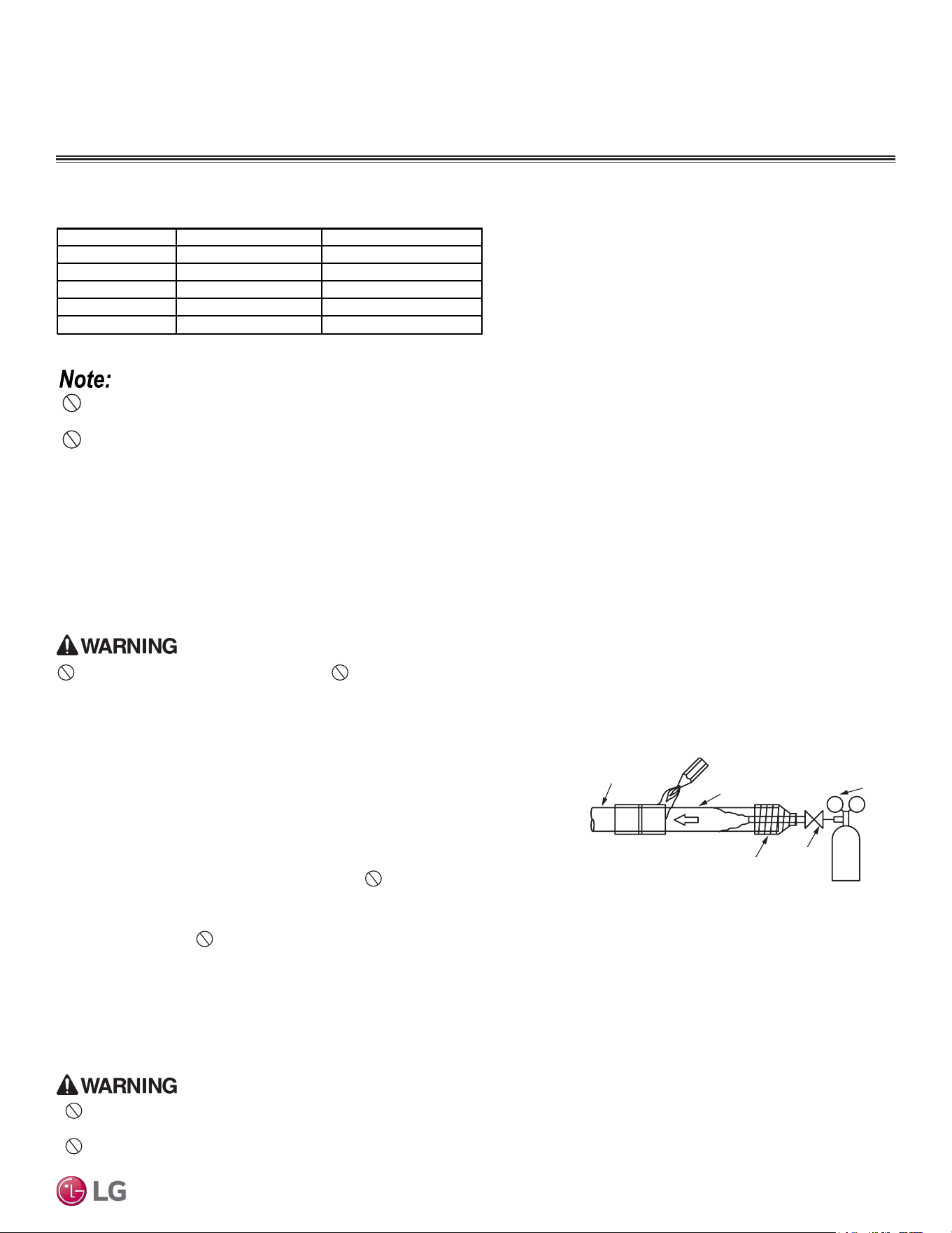
35
General Refrigerant Piping System Information
Due to our policy of continuous product innovation, some specications may change without notication.
© LG Electronics U.S.A., Inc., Englewood Cliffs, NJ. All rights reserved. “LG” is a registered trademark of LG Corp.
13.0 - 18.0
24.6 - 30.4
39.8 - 47.7
T
ightening Torque for Flare Nuts.
T
ightening the Flare Nuts
1. When connecting the flare nuts, coat the flare (outside only) with
polyvinyl ether (PVE) refrigeration oil only.
2. Initially hand tighten the flare nuts using three (3) or four (4) turns.
3. To finish tightening the flare nuts, use both a torque wrench and a backup wrench.
4. After all the piping has been connected and the caps have been tightened, check for refrigerant gas leaks.
Loosening the Flare Nuts
Always use two (2) wrenches to loosen the flare nuts.
Do not use polyolyester (POE) or any other type of mineral oil as a thread lubricant. These lubricants are not compatible with the PVE oil
used in this system and create oil sludge leading to equipment damage and system malfunction.
Pipe Size (in. O.D.) Tightening Torque (ft-lbs.)
1/2
1/4
5/8
3/8
3/4
Outside Diameter (mm)
6.35
9.52
12.7
15.88
19.05
45.4 - 59.3
71.5 - 87.5
Do not add any contaminants inside the refrigerant piping.
Figure 37: Refrigerant Pipe Brazing.
Pressure-reducing
Valve
Valve
Taping
Nitrogen
Pipe to
be brazed
Refrigerant
Piping
Brazing Practices
1. Joints are brazed in the field. Single Zone refrigeration system components
contain very small capillary tubes, small orifices, electronic expansion valves, oil
separators, and heat exchangers that can easily become blocked. Proper system
operation depends on the installer using best practices and utmost care while
assembling the piping system.
2. Store pipe stock in a dry place; keep stored pipe capped and clean.
3. Blow clean all pipe sections with dry nitrogen prior to assembly.
4. Always use a non-oxidizing material for brazing. Do not use flux, soft solder, or
anti-oxidant agents. If the proper material is not used, oxidized film will accumulate
and clog or damage the compressors. Flux can harm the copper piping or refrigerant oil.
5. Use a tubing cutter, do not use a saw to cut pipe. De-bur and clean all cuts before assembly.
6. Brazing joints:
• Use a dry nitrogen purge operating at a minimum pressure of three (3) psig and maintain a steady flow.
• Use a 15% silver phosphorous copper brazing alloy to avoid overheating and produce good flow.
• Protect isolation valves, electronic expansion valves, and other heat-sensitive control components from excessive heat with a wet rag or
heat barrier spray.
Do not braze in an enclosed location. Do not allow the refrigerant to leak during brazing. Always test for gas leaks
before and after brazing.
If the refrigerant combusts, it generates a toxic gas the will cause physical injury or death.
FLARING AND BRAZING PROCEDURES
•
Do not allow the refrigerant to leak during brazing; if the refrigerant combusts, it generates a toxic gas. There is risk of fire, explosion, and
physical injury or death.
• Do not braze in an enclosed location, and always test for gas leaks before / after brazing. There is risk of fire, explosion, and physical
injury or death.

36
Single Zone Mega, Standard Eciency, and Mega 115V Wall Mounted Installation Manual
Due to our policy of continuous product innovation, some specifications may change without notification.
©LG Electronics U.S.A., Inc., Englewood Cliffs, NJ. All rights reserved. “LG” is a registered trademark of LG Corp.
REFRIGERANT PIPING CONNECTIONS
Installation Overview
Figure 38: Installation and Piping Connection Overview (Appearances Will Vary
Depending on Model).
Installation
Single Zone Mega, Standard Efficiency, and Mega
115V Wall-Mounted systems are one-to-one systems.
There is a direct piping connection between the
outdoor unit and the indoor unit. The figure at right
illustrates the basic pipe connections between the
outdoor and indoor unit. Refer to the illustration when
proceeding with pipe connections.
The illustration shows the indoor unit being installed at
a higher position than the outdoor unit. However, if the
outdoor unit is installed at a higher position than the
indoor unit, the basic pipe connections are the same.
Refer to the “Connection Limitations” section for
specific length limitations in conjunction with outdoor
unit and indoor unit positioning.
• When proceeding with piping connections, adhere to
pipe support spacing lengths as shown in the General
Refrigerant Piping System Information section. Refer
to the “Pipe Supports” section for information on
using clamps and pipe support materials.
• Always adhere to local codes regarding piping and
accurate support spacing along the piping system.
• Always include insulation on all refrigerant and drain
piping to ensure condensate does not form and
cause damage to walls, floors, etc.
Connecting Cable
Vinyl tape (Wide)
Saddle
Gas Piping
Liquid Piping
Additional Drain Pipe
Vinyl Tape (Narrow)
Drain Hose
Installation Plate
Sleeve
Bushing-Sleeve
Sealant
• Install after drainage test.
• For the drainage test,
remove the air filters and
pour water into the heat
exchanger.
Bend the pipe as closely
to the wall as possible,
but be careful not to break it.
Additional field-provided accessories /
parts / tools that are needed for
installation.
Air Intake Vents
Air Outlet Vents
Base Plate
Front Grille
On/Off Button
Signal Receiver
Display
Air Deflector
(Vertical Louver & Horizontal Vane)
Air Outlet
Air Filter
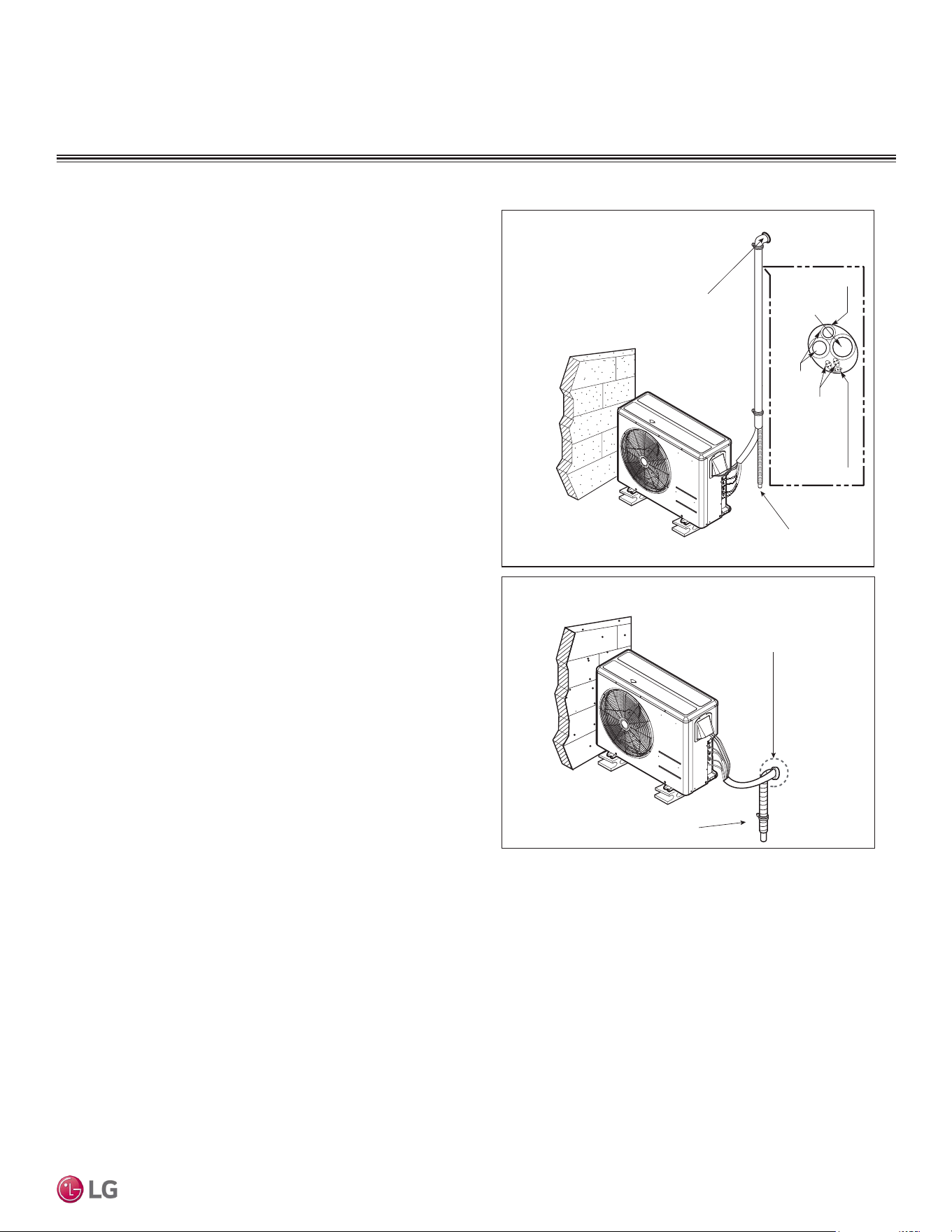
37
Refrigerant Piping Connections
Due to our policy of continuous product innovation, some specifications may change without notification.
©LG Electronics U.S.A., Inc., Englewood Cliffs, NJ. All rights reserved. “LG” is a registered trademark of LG Corp.
REFRIGERANT PIPING CONNECTIONS
Special Applications
If an additional drain hose is necessary, the end of drain outlet must
be routed above the ground. Secure the drain hose appropriately.
When the Outdoor Unit is Installed Below the Indoor Unit:
1. Use a conduit, piping set cover, or bundle the (separately) insu-
lated refrigerant piping, the drain hose, and the communications /
connection (power) cable together.
2. Make sure to include some slack in the wiring. Wiring must be
installed in an upwards direction to prevent water from accessing
into the control box.
3. Secure the conduit, piping set cover, or bundle along the outside
wall using saddles or a similar type of piping support.
4. Seal any openings in the wall that are around the piping.
When the Outdoor Unit is Installed Above the Indoor Unit:
1. Use a conduit, piping set cover, or bundle the (separately)
insulated refrigerant piping and the communications / connection
(power) cable together up to the outdoor unit service valves.
2. Make sure to include some slack in the wiring. Wiring must be
installed in upwards direction to prevent water from traveling into
the control box.
3. If necessary, secure the conduit, piping set cover, or bundle
along the outside wall using saddles or a similar type of piping
support.
4. Ensure the insulated drain hose from the indoor unit is installed
away from the outdoor unit, and in a downwards direction. If nec-
essary, secure along the outside wall using saddles or a similar
type of support.
5. Seal any openings in the wall that are around the piping.
Figure 39: Special Applications.
Special Applications
Insulation
Drain Hose
Piping
Communication
Cables
Power Wiring
Seal the small access hole
in the wall around the piping.
Outdoor Unit Below Indoor Units
Outdoor Unit Above Indoor Units
Seal the small access hole
in the wall around the piping.
Drainage from the Indoor Units
Drainage from the Indoor Units

38
Single Zone Mega, Standard Eciency, and Mega 115V Wall Mounted Installation Manual
Due to our policy of continuous product innovation, some specifications may change without notification.
©LG Electronics U.S.A., Inc., Englewood Cliffs, NJ. All rights reserved. “LG” is a registered trademark of LG Corp.
REFRIGERANT PIPING CONNECTIONS
Pipe Size
(in. O.D.)
Outside
Diameter (mm)
Torque
(ft-lbs.)
1/4 6.35 13.0 - 18.0
3/8 9.52 24.6 - 30.4
1/2 12.7 39.8 - 47.7
5/8 15.88 45.4 - 59.3
3/4 19.05 71.5 - 87.5
Table 19: Torque Wrench Tightening.
Outdoor Unit Connections
1. Remove the piping cover or piping / control box cover (configuration depends on outdoor unit model) from the unit by loosening the fas-
tening screws.
2. Align the center of the refrigerant piping and corresponding connection as shown.
3. Refer to the figures below for liquid and gas (vapor) piping attachments onto the outdoor unit.
4. Place a couple of drops of PVE refrigerant oil on outside of the flare before assembling.
Do not add any contaminants. Tighten the
flare nut initially by hand.
5. Finish tightening the flare nut with a torque wrench until the wrench clicks. Follow torque guidelines in the table below. See figures for
correct connection points.
Terminal Block
Piping / Control
Box Cover
Piping Connection
Cover
Outdoor Unit
Control Box
Cover
Terminal Block
Outdoor Unit
Torque Wrench
Liquid Side Piping
(Smaller Diameter)
Vapor Side Piping
(Larger Diameter)
Figure 40: LSU090-120HEV2,
LSU090-120HFV3, LSU090-120HXV2 Piping /
Control Box Cover Removal (Appearances Will
Differ Depending on Model).
Figure 41: LSU180-240HEV2,
LSU180-240HFV3 Piping / Control Box Cover
Removal.
Figure 42: Outdoor Unit Piping Connection
(Appearances Will Differ Depending on Model).
Figure 43: Pipe Attachment.
Outdoor Unit Connections

39
Refrigerant Piping Connections
Due to our policy of continuous product innovation, some specifications may change without notification.
©LG Electronics U.S.A., Inc., Englewood Cliffs, NJ. All rights reserved. “LG” is a registered trademark of LG Corp.
REFRIGERANT PIPING CONNECTIONS
Right Side
Piping
Piping / Drain Hose Holder
Left Side Piping
Rear
Piping
Piping / Drain Hose Holder
Figure 44: Removing the Bottom Cover. Figure 45: Removing the Bottom Cover,
Alternate View.
Unfold
slowly
downward
Bend from
downward
position
Accessing and Positioning the Indoor Unit Piping / Connections (HEV2,
HFV3, and HXV2)
1. Unsnap the piping / drain hose holder (L-bracket) out from the indoor unit chassis. Prop it open between the indoor unit chassis and
installation plate to separate the bottom of the indoor unit from the wall. This will allow for more working space.
2. Remove the piping port cover.
3. Position the piping by unfolding and bending the piping slowly
downward first as shown, then to the left or right (pre-chosen
following installation guidelines and application needs) as shown.
Secure piping with the piping holder.
Figure 46: Propping Open the Piping / Drain Hose Holder (L-bracket). Figure 47: Back of Indoor Unit.
Figure 48: Bending Piping at Rear of Indoor Unit.
To access the indoor unit piping port connections, and
to make the indoor unit installation procedure easier,
it is recommended that the bottom cover be removed
first.
1. Unsnap the bottom cover at its top left and right
sides (Location 1).
2. Unsnap each of the three (3) or four (4) small
C-hooks located in the middle of the bottom cover
(Location 2). Number of C-hooks present depends
on model of indoor unit.
3. Lift the three (3) to four (4) hinges on the bottom
cover up and out of the channels molded to the
left, right, and middle of the indoor unit (Location
3). Number of hinges present depends on model
of indoor unit.
4. Set aside the bottom cover to re-install after all
procedures are complete.
3
3
3
Removing the Indoor Unit Bottom Cover (HEV2, HFV3, and HXV2)
Indoor Unit Connections

40
Single Zone Mega, Standard Eciency, and Mega 115V Wall Mounted Installation Manual
Due to our policy of continuous product innovation, some specifications may change without notification.
©LG Electronics U.S.A., Inc., Englewood Cliffs, NJ. All rights reserved. “LG” is a registered trademark of LG Corp.
REFRIGERANT PIPING CONNECTIONS
• Do not bend the piping directly backwards or to the left or right sides without bending it downward first; this will damage the indoor unit
piping.
• Do not forcibly press the refrigerant piping onto the bottom frame or the front grille; this will damage the indoor unit piping and / or
indoor unit frame.
• Ensure the piping is straight. Do not kink the piping; this will damage the indoor unit and piping.
Figure 49: Improper Piping Bending.
Figure 50: Keep Piping Straight;
Avoid Kinks.
Piping Installation When Piping is on the Left Side (HEV2,
HFV3, and HXV2)
• See the Electrical System Installation section for information on
how to connect the communication / connection (power) cable from
the outdoor unit.
• For left-side piping, it is recommended that the communication /
power connections are complete before starting the piping connec-
tions.
1. Insert drain hose on left (feature will differ depending on model of
indoor unit).
2. Align the center of the refrigerant piping and corresponding con-
nection as shown on the next page.
3. Place a couple of drops of refrigerant oil on outside of the flare
before assembling. Do not add any contaminants. Tighten
the flare nut initially by hand.
4. Finish tightening the flare nut with a torque wrench until the
wrench clicks. Follow torque guidelines in the table on the next
page.
When tightening the are nut with a torque wrench, ensure the direction
for tightening follows the arrow on the wrench.
5. Bundle the refrigerant piping, drain hose, and communication /
connection (power) cable together. Ensure that the drain hose is
located at the bottom of the bundle.
• If using a conduit for the power wiring / communications cable,
see the next page.
Figure 51: Piping Installation When Piping is on the Left Side.
Accessing and Positioning the Indoor Unit Piping / Connections (HEV2, HFV3, and HXV2), continued.
Positioning the drain hose at the top of the bundle can cause condensate to overow from the drain pan in the inside of the indoor unit.
Indoor Unit Connections
Left Side Piping
Drain Hose
Piping
Connection
Cable
Tape
Drain Hose

41
Refrigerant Piping Connections
Due to our policy of continuous product innovation, some specifications may change without notification.
©LG Electronics U.S.A., Inc., Englewood Cliffs, NJ. All rights reserved. “LG” is a registered trademark of LG Corp.
REFRIGERANT PIPING CONNECTIONS
Accessing and Positioning the Indoor Unit Piping / Connections (HEV2, HFV3, and HXV2), continued.
Using a Conduit for IDU Wiring / Cable Installation
Use a liquidtight 3/4 inch elbow connector for exible conduit.
1. Prop indoor unit away from wall bracket.
2. Guide communication / connection (power) cable insulation into the conduit.
• Check local, state, and federal codes when choosing a conduit size.
• For systems with wiring greater than 130 feet, see the “Communication / Connection (Power) Cable Specifications
from Outdoor Unit to Indoor Unit” in the Electrical System Installation section for information.
3. Attach conduit using the liquidtight 3/4 inch elbow connector.
4. Reassemble the indoor unit properly onto the wall bracket.
5. If conduit is not used, see pages in this section for refrigerant piping, condensate drain, power wiring / communica-
tion cable bundling information.
6. To protect the piping, condensate drain, and conduit from the elements, add a lineset cover from the indoor access
hole to the outdoor unit.
Indoor Unit Piping Flare Nut Field-
Installed
Piping
Pipe Size (in. O.D.) Outside Diameter (mm) Torque (ft-lbs.)
1/4 6.35 13.0 - 18.0
3/8 9.52 24.6 - 30.4
1/2 12.7 39.8 - 47.7
5/8 15.88 45.4 - 59.3
3/4 19.05 71.5 - 87.5
Table 20: Torque Wrench Tightening.
Figure 52: Piping Installation When Piping is on the Right Side.
Piping Installation When Piping is on the Right Side (HEV2,
HFV3, and HXV2)
See the Electrical System Installation section for information on how to connect
the communication / connection (power) wiring from the outdoor unit.
1. Align the center of the refrigerant piping and corresponding connection
as shown.
2. Place a couple of drops of refrigerant oil on outside of the flare before
assembling. Do not add any contaminants. Tighten the flare nut
initially by hand.
3. Finish tightening the flare nut with a torque wrench until the wrench
clicks. Follow torque guidelines in the table below.
When tightening the are nut with a torque wrench, ensure the direction for
tightening follows the arrow on the wrench.
4. Bundle the refrigerant piping, drain hose, and communication / con-
nection (power) cable together. Ensure that the drain hose is located
at the bottom of the bundle.
• If using a conduit for the power wiring / communications cable, see
below.
Positioning the drain hose at the top of the bundle can cause condensate to
overow from the drain pan in the inside of the indoor unit.
Figure 53: Indoor Unit Connection.
Figure 54: Liquidtight 3/4 Inch Elbow Connector
Attached to Flexible Conduit.
Indoor Unit Connections
Right Side Piping
Piping
Connection
Cable
Tape
Drain Hose

42
Single Zone Mega, Standard Eciency, and Mega 115V Wall Mounted Installation Manual
Due to our policy of continuous product innovation, some specifications may change without notification.
©LG Electronics U.S.A., Inc., Englewood Cliffs, NJ. All rights reserved. “LG” is a registered trademark of LG Corp.
REFRIGERANT PIPING CONNECTIONS
Depending on the installation location, it could be necessary to
install factory-supplied drain plug(s). See the section Outdoor Unit
Location Selection for information in reference to ODU placement.
Ensure drain piping is insulated. Drain water from the defrost mode will
freeze and build up in the outdoor unit, impairing heating performance,
and even will damage the outdoor unit.
Installing Outdoor Unit Drain Plug / Piping
1. See diagrams at right for drain connection, drain caps, and drain
washer locations specific to each outdoor unit. Components and
location differ depending on model of outdoor unit.
2. Connect field-supplied vinyl condensate piping to the outdoor
unit drain connection. If the field-supplied vinyl piping is too long,
position it to prevent kinks.
Check local codes for materials approved for eld-suppled condensate
drain piping.
ODU Condensate Drain Piping Installation
Figure 55: HEV2, HFV3 Outdoor Unit Drain Connection Components
Figure 56: HXV2 ODU Drain Connection Components
Condensate Drain Hose Installation; from Indoor
Unit to Drain System (HEV2, HFV3, and HXV2)
Refer to the diagrams and follow proper installation and the position of the drain hose along the refrig-
erant piping installation path to avoid leaks. After the drain hose is set in place, always follow with leak
/ pressure testing and deep evacuation procedures of the refrigerant piping to be sure all refrigerant
piping is properly installed. Re-check and retest as necessary.
• Drain hose is routed from the indoor unit through the structure (wall) to the outdoor. It must slope at an angle where it is higher at the
indoor unit and lower toward the outdoor area, thereby letting gravity push any condensation down and out.
• The drain hose might need to be extended so that condensate can be properly routed away.
• The drain hose extension must be properly insulated to ensure condensation will not damage walls, floors, etc. Foamed polyethylene or
equivalent of at least 5/16 inches thick is required.
Downward Slope
to Outdoor
for Proper Drainage
Indoor
Unit
Piping
Indoor Outdoor
Indoor Unit
Drain Hose
Indoor Unit
Drain Hose
Insulation
(>4 to 12 inches long
and 5/16 inches thick)
Drain Hose
Extension
Choosing the Indoor Unit Condensate Drain Hose
Connection Side (HEV2, HFV3, and HXV2)
1. Remove the drain plug on left or right side depending on the piping installation. Insert the
drain hose on the left side when left side piping is used; install the drain hose on the right
side when right side piping is used.
2. Plug up the unused drain hose hole with a drain cap.
3. Install the drain hose onto the drain connection, and firmly attach it to the indoor unit using
a type “E” screw.
Figure 57: Choosing the Location of the Drain
Hose Connection (HEV2, HFV3, HXV2).
Figure 58: Installing the Drain Hose.
Figure 59: Correct Slope Angle for Drain Hose. Figure 60: Indoor Unit Drain Hose Extension.
Outdoor Unit Drain Piping / Indoor Unit Drain Hose
Drain Cap
Drain Washer
Drain Connection
LSU090HXV2, LSU120HXV2
Drain Washer
LSU090HEV2, LSU120HEV2
Drain Cap
Drain Connection
Drain Connection
Drain Washer
Drain Cap
LSU180HEV2, LSU240HEV2
LSU090HFV3, LSU120HFV3 LSU180HFV3, LSU240HFV3

43
Refrigerant Piping Connections
Due to our policy of continuous product innovation, some specifications may change without notification.
©LG Electronics U.S.A., Inc., Englewood Cliffs, NJ. All rights reserved. “LG” is a registered trademark of LG Corp.
REFRIGERANT PIPING CONNECTIONS
• Insert the drain hose >two (2) inches so it won’t pull out of the
field-supplied drain pipe.
•
Avoid piping the drain hose as shown in the diagrams in the
figure below. These methods are incorrect and can cause leaks at
the indoor unit site.
Figure 61: Inserting the Drain Hose >Two (2) inches Into the Field-Sup-
plied Drain Pipe.
Insert the drain
hose >2 inches
so it won’t be pulled
out of the field-
supplied drain pipe.
>2 inches
Drain Hose
Interior Wall
Vinyl Chloride
Drain Pipe
Exterior Wall
Accumulated
drain water
Tip of Drain Hose
In Container
Tip of Drain
Hose Pointing
Up
Tip of Drain Hose
In Water
Air
Kinks
Water
Leak
Water
Leak
Ditch
Less than
2 inch Gap
Between Bottom
of Drain Hose and
Ground
Water
Leak
No rainwater trap
Drain Hose and
Ground are Parallel
Horizontal Drain Hose
>6-1/2 feet
Drain Hose Inserted
<2 inches
Bundle Taped in
Downward
Direction
Less than 2 inch Gap
Buried Pipe
Upward slope
to outdoor
can cause indoor
leaks!
Indoor
Unit
Indoor
Unit
Indoor
Unit
Indoor
Unit
Water
Leak
Indoor
Unit
Indoor
Unit
Water
Leak
Indoor
Unit
Water
Leak
Indoor
Unit
Water
Leak
Drain Hose
Installed in
Upward Direction
Figure 62: Incorrect Slope Angles for the Drain Hose.
Condensate Drain Hose Installation; from Indoor Unit to Drain System (HEV2, HFV3, and HXV2), continued.
Indoor Unit Drain Hose
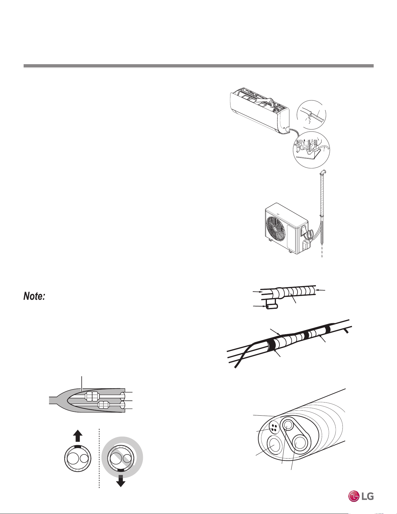
44
Single Zone Mega, Standard Eciency, and Mega 115V Wall Mounted Installation Manual
Due to our policy of continuous product innovation, some specifications may change without notification.
©LG Electronics U.S.A., Inc., Englewood Cliffs, NJ. All rights reserved. “LG” is a registered trademark of LG Corp.
REFRIGERANT PIPING CONNECTIONS
Figure 63: Checking for Leaks at the Indoor Unit.
Figure 64: Bundling the Connection Components (From Outdoor Unit to
Indoor Unit).
Vinyl tape (narrow)
Connection pipe
Connecting cable
Vinyl tape (wide)
Wrap with vinyl tape
Indoor unit pipe
Pipe
Bundling
If a conduit or piping set cover is not used on the connection from
the outdoor unit to the interior, bundle both separately insulated
refrigerant pipes, the drain hose, and outdoor unit to indoor unit
communication / connection (power) cable together with wide vinyl
tape.
1. Both piping must be fully and separately encased in insulation
material: Overlap the field installation piping insulation material
and the indoor unit piping insulation material.
2. Bind together the two pipes, using vinyl tape. Make sure there
are no gaps during the binding.
3. Be sure the cutting line is placed upward.
4. Wrap the rear piping section with narrow vinyl tape.
5. Continue to wrap the indoor unit pipe as connected to the outdoor
connection pipe.
6. Using a wider vinyl tape, bundle the piping and drain hose
together.
• Tape must be sufficient to cover the piping in order to fit into the
rear piping housing area at the back of the indoor unit.
Checking the Indoor Unit Drain Hose
for Leaks
1. Pour a glass of water on the evaporator.
2. Verify that the water flows appropriately through and out of the
drain hose without any leaks.
Figure 65: Cutaway of Proper Bundling.
Drain Pan
Drain
Hose
Check for Leaks
Drain Hose Connection
Check
for Leaks
Indoor Unit Drain Hose
• Always include insulation on all refrigerant and drain piping to
ensure condensate does not form and cause damage to walls,
floors, etc.
• For systems with wiring greater than 130 feet, see the “Commu-
nication / Connection (Power) Cable Specifications from Outdoor
Unit to Indoor Unit” in the Electrical System Installation section for
information.
Figure 66: Cutaway of.Proper Pipe and Cable Bundling.
Cut Line
Cut Line at Top
Piping
Connection
Cable
Tape
Drain Hose

45
Insulation
Due to our policy of continuous product innovation, some specifications may change without notification.
©LG Electronics U.S.A., Inc., Englewood Cliffs, NJ. All rights reserved. “LG” is a registered trademark of LG Corp.
INSULATION
Figure 67: Typical Insulation Butt-
Joint at Indoor Unit Casing.
Figure 68: Typical Refrigerant
Flare Fitting Insulation Detail.
Refrigerant Piping System Insulation
For information regarding insulation for underground or penetration situations, see the “General Refrigerant Piping System Information” section.
All refrigerant piping from the outdoor unit to the indoor units must be insulated correctly for safety and usage. Refrigerant piping, field-pro-
vided isolation ball valves (if present), service valves, and elbows must be properly and completely insulated using closed cell pipe insulation
(up to the indoor unit piping connections). To prevent heat loss / heat gain through the refrigerant piping, all refrigerant piping including liquid
lines and vapor lines must be insulated separately. Insulation must be a minimum 1/2 inches thick, and thickness will need to be increased
based on ambient conditions and local codes. Table on next page lists minimum wall thickness requirements for Ethylene Propylene Diene
Methylene (EPDM) insulation.
Inside the outdoor unit, maximum pipe temperature is 248°F and minimum pipe temperature is -40°F. For field insulation of refrigerant piping
between outdoor units and indoor units, consider the following pipe temperature ranges for an operating heat pump system:
• Heating mode refrigerant temperature ranges: Liquid = 75-118°F; High Pressure Vapor = 95-220°F
• Cooling mode refrigerant temperature ranges: Liquid = 75-118°F; Low Pressure Vapor = 40-90°F
All insulation joints must be glued with no air gaps. Insulation material must fit snugly against the refrigeration pipe with no air space between
it and the pipe. Do not allow insulation passing through pipe hangers, inside conduit, and/or sleeves to be compressed. Protect insulation
inside hangers and supports with a second layer. All pipe insulation exposed to the sun and outdoor elements must be properly protected
with PVC, aluminum vapor barrier, or alternatively placed in a weather-resistant enclosure such as a pipe rack with a top cover; and meet
local codes.
Surface of
Indoor Unit Casing
Field-Provided
Pipe Insulation
Figure 69: Insulating the Shut Off / Insulation Ball Valve (If Present).
Indoor Unit
Insulation (Field Supplied)
Cable Tie, etc.
(Field Supplied)
Refrigerant Piping
Always include plenty of insulation on all refrigerant and drain piping to ensure condensate does not form and cause damage to walls, oors, etc.
46
Single Zone Mega, Standard Eciency, and Mega 115V Wall Mounted Installation Manual
Due to our policy of continuous product innovation, some specifications may change without notification.
©LG Electronics U.S.A., Inc., Englewood Cliffs, NJ. All rights reserved. “LG” is a registered trademark of LG Corp.
INSULATION
1. Typical Conditioned Location
A building plenum or space that contains conditioned air that does not exceed 80°F DB.
2. Special Conditioned Location
1. When the location is air conditioned, but there is severe temperature/humidity difference due to high ceilings.
• Church, auditorium, theater, lobby, etc.
2. When the location is air conditioned, but internal temperature/humidity are high.
• Bathroom, swimming pool, locker room, etc.
3. Typical Unconditioned Location
An unconditioned space inside a building.
Minimum Refrigerant Pipe Ethylene Propylene Diene Methylene (EPDM) Insulation Wall Thickness Requirements
4. Special Unconditioned Location: If conditions 1 and 2 below are present.
1. An unconditioned space or plenum of a building.
2. An area where there is an elevated humidity level.
Classication / Piping O.D.
Air-conditioned location Non-air conditioned location
1. Typical Conditioned
Location
2. Special Conditioned
Location
3. Typical Unconditioned
Location
4. Special Unconditioned
Location
Liquid pipe
ø1/4 inch
>1/2 inches >1/2 inches >1/2 inches >1/2 inches
ø3/8 inch
≥ø1/2 inch >1/2 inches >1/2 inches >1/2 inches >1/2 inches
Vapor pipe
ø3/8 inch
>1/2 inches
>3/4 inches >3/4 inches
>1 inch
ø1/2 inch
ø5/8 inch
ø3/4 inch
ø7/8 inch
ø1 inch
ø1-1/8 inches
>3/4 inches
ø1-1/4 inches
>1 inch >1 inch
ø1-3/8 inches
ø1-1/2 inches
ø1-3/4 inches
Table 21: Minimum Refrigerant Pipe EPDM Insulation Wall Thickness Requirements.
1
• Do not insulate gas and liquid pipes together as this can result in pipe leakage and malfunction due to extreme temperature fluctuations.
• Always properly insulate the piping. Insufficient insulation will result in condensation, reduced heating/cooling performance, etc. Also, if the
pipes aren’t insulated properly, condensation could potentially cause damage to building finishes. Pay special attention to insulating the
pipes installed in the ceiling plenum.
• Fully insulate the piping connections.
• Follow locals codes and the designer’s instructions when selecting ethylene propylene diene methylene (EPDM) insulation wall thickness.
1
The thickness of the above insulation material is based on heat conductivity of 0.61 Btu/in/h/ft
2
/°F.
5. Additional Insulation for Indoor Units May be Required in Humid Environments.
The air conditioner factory insulation has been tested according to “ISO Conditions with Mist,” and it satisfies the requirements. If the system
has been operating for a long time in a high humidity environment (dew point temperature: more than 73°F), condensate is likely to form. If
this happens, install 3/8 inch thick EPDM insulation that is plenum-rated with a heat-resistance factor of more than 248°F.
47
Electrical System Installation
Due to our policy of continuous product innovation, some specifications may change without notification.
©LG Electronics U.S.A., Inc., Englewood Cliffs, NJ. All rights reserved. “LG” is a registered trademark of LG Corp.
ELECTRICAL SYSTEM INSTALLATION
• All power wiring and communication cable installation must be performed by trained service providers working in accordance with local,
state, and National Electrical Code (NEC) / UL / ETL federal regulations related to electrical equipment and wiring, and following the
manufacturer product diagrams, requirements, and instructions in this manual. Failure to do so will lead to electric shock which can cause
physical injury or death.
• Verify that main power to the unit is completely off before proceeding. Follow all safety and warning information outlined at the beginning of
this manual. Failure to do so will cause electric shock and bodily injury or death.
• Familiarize yourself with the location of the circuit breaker. Be sure that a circuit breaker or some other emergency power cutoff device is in
place before any power wiring is done to the system. Failure to do so will cause bodily injury or death.
• Never touch any power lines or live cables before all power is cutoff to the system. To do so will cause bodily injury or death.
• Undersized wiring will lead to unacceptable voltage at the unit and will cause a fire, which will cause bodily injury or death.
• Properly ground the Single Zone outdoor and indoor units. Ground wiring is required to prevent accidental electrical shock, bodily injury,
and death during current leakage.
• Ground wiring must always be installed by a trained technician.
• Install appropriately sized breakers / fuses / overcurrent protection switches and wiring in accordance with local, state, and NEC regulations
related to electrical equipment and wiring, and following the instructions in this manual. Using an oversized breaker or fuse will result in
electric shock, physical injury or death.
• Do not connect ground wire to refrigerant, gas, or water piping; to lightning rods; to telephone ground wiring; or to the building plumb-
ing system. Failure to properly provide a NEC-approved earth ground will result in electric shock, fire, physical injury or death.
• Consider ambient conditions (temperature, direct sunlight, inclement weather, etc.) when selecting, installing, and connecting the power
wiring.
• Properly ground the Single Zone outdoor and indoor unit. Improperly connected ground wire can cause communication problems from
electrical noise and motor current leakage. Ground wiring must always be installed by a trained technician.
• Install appropriately sized breakers / fuses / overcurrent protection switches and wiring in accordance with local, state, and NEC regulations
related to electrical equipment and wiring, and following the instructions in this manual. Using an oversized breaker or fuse will result in
equipment malfunction and property damage.
• Do not connect ground wire to refrigerant, gas, or water piping; to lightning rods; to telephone ground wiring; or to the building plumbing
system. Failure to properly provide a NEC-approved earth ground can result in property damage and equipment malfunction.
• Do not operate the air conditioning system until the refrigerant piping installation is complete. Operating the system before refrigerant
piping is finalized will damage the compressor.
Figure 70: Close up of a Typical Ring Termi-
nal.
Power Wiring / Communication Cable Connections
Best practice dictates using solderless ring or fork terminals at all power wiring and com-
munication cable terminations. Use copper bearing ring or fork terminals;
do not use
galvanized or nickel plate over steel. Use appropriate crimping tool to attach the ring or fork
terminals at all power wiring and control cable terminations.
To Install a Ring or Fork Terminal:
1. Trim the wiring with wire cutters or pliers, then strip the insulation to expose the strand
wiring to about 3/8 inches.
2. Using a ring terminal fastener or pliers, securely clamp a ring terminal to each stripped
wire end.
Ring Terminal
Wiring / Cable
Figure 71: Distance Between the Terminal
Connections.
>1/4
inches
Safety Guidelines
LS090-120HEV2, LS090-120HFV3, and LS090-120HXV2 indoor units and outdoor units have similar frames; however,
LS090-120HEV2 and LS090-120HFV3 systems require 208-230V, 60Hz, 1ph power supply. LS090-120HXV2 systems require
115V, 60Hz, 1ph power supply. Verify which system is being installed. An incorrect power supply will result in electric shock,
re, physical injury, or death.

48
Single Zone Mega, Standard Eciency, and Mega 115V Wall Mounted Installation Manual
Due to our policy of continuous product innovation, some specifications may change without notification.
©LG Electronics U.S.A., Inc., Englewood Cliffs, NJ. All rights reserved. “LG” is a registered trademark of LG Corp.
ELECTRICAL SYSTEM INSTALLATION
Strip to 3/8"
Ring
Terminal
Connecting Cable
Connecting cable
Loosening the
terminal block
screw
Fastening the
wiring tightly
Figure 72: Adding a Ring Terminal to the
Wiring.
To Connect the Wiring to the Terminals:
1. Remove the JIS terminal screws from the (outdoor unit or indoor unit) terminal plate with a
JIS screwdriver. (See information about LG terminal connections below.)
2. Position the ring terminal around the terminal, place the terminal screw in the ring, and
tighten to the terminal plate using a JIS screwdriver.
• Firmly attach the wire; secure in a way to prevent external forces from being imparted to
the terminal block.
• Use an appropriately sized JIS screwdriver for tightening the terminals.
•
Do not overtighten the connections; overtightening will damage the terminals.
If ring terminals or fork terminals are not available, then:
• Do not terminate different gauge wires to the power terminal block. (Slack in the wiring
will generate heat.)
• When terminating wires of the same thickness, follow the instructions demonstrated in the
figures below.
•
Never apply line voltage power to the communications cable terminal block. If contact
is made, the PCBs will be damaged.
• Always include some allowance in the wiring length when terminating. Firmly attach the
wiring or cable, but provide some slack to facilitate removing the electrical panels while
servicing, and to prevent external forces from damaging the terminal block.
:Copper Wire
Terminate multiple power wires of
the same gauge to both sides.
Do not terminate two wires on
one side.
Do not terminate different gauge
wires to a terminal block.
If power wires are not properly terminated and rmly attached, there is risk of re, electric shock,
and physical injury or death.
WARNING
Figure 73: Tightening the Ring Terminal to the
Terminal Plate.
Connections and Specications
Figure 74: Proper and Improper Power Wiring Connections.
Terminal Connections
LG uses a “JIS” type of screw for all terminals; use a JIS screwdriver to tighten and
loosen these screws and
avoid damaging the terminal. Do not overtighten
the connections — overtightening will damage the terminals — but firmly and securely
attach the wiring in a way to prevent external forces from being imparted to the termi-
nal block.
• The terminals labeled “GND” are NOT ground terminals. The terminals labeled
ARE ground terminals.
• Polarity matters. Always connect “A” to “A” and “B” to “B.”
• Do not include splices or wire nuts in the communication cable.
Figure 75: JIS Screws.
Power Wiring / Communication Cable Connections, continued

49
Electrical System Installation
Due to our policy of continuous product innovation, some specifications may change without notification.
©LG Electronics U.S.A., Inc., Englewood Cliffs, NJ. All rights reserved. “LG” is a registered trademark of LG Corp.
ELECTRICAL SYSTEM INSTALLATION
• HEV2 and HFV3 systems operate at 1Ø, 208-230V, 60Hz.
• HXV2 systems operate at 1Ø, 115V, 60Hz
• Power wiring / power wiring gauge to the outdoor unit(s) must be solid or stranded, and
must comply with all National Electrical Code (NEC), UL, and local electrical codes.
• The indoor unit is powered by the outdoor unit.
• Power supply, wire types and sizes, and circuit breaker must be selected based on NEC, UL, and local codes.
Maximum allowable voltage fluctuation ±10% or nameplate rated value.
• Properly ground the outdoor unit and indoor unit per NEC, UL, and local codes.
• Ground wire must be longer than the common power / communication wires.
• Connect the wiring firmly so the wires cannot be easily pulled out.
• Refer to the inside of the chassis cover or control cover for circuit and terminal block diagrams.
• Always match color codes of each wire and follow wiring diagram.
• Do not install power wiring to the outdoor unit and the communication / connection (power) cable to the
indoor unit in the same conduit. Use separate conduits.
Figure 76: Power Wiring
Conduit.
Figure 77: Single Zone Outdoor Unit Power Wiring
Diagram.
7/16" ± 1/8"
13/16"
GN/YL
Power Wiring, Ground
to Outdoor Unit
Power Supply / Power Wiring Specifications
Refer to Electrical Data table for ampere ratings. Properly size all circuit breakers / fuses, wiring and eld provided components per local codes.
There is risk of re, electric shock, explosion, physical injury or death.
• All power wiring installation must be performed by trained service providers working in accordance with local, state, and NEC regulations
related to electrical equipment and wiring, and following the instructions in this manual. Failure to do so will lead to electric shock and bodily
injury or death.
• Use specified wiring for connections, and ensure that external force is not imparted to terminal connections. It will generate heat and / or
cause a fire, resulting in physical injury or death.
• Use heat-proof electrical wire capable of withstanding temperatures up to 167°F to avoid wiring malfunction and electrical shock, which will
cause physical injury or death.
• Install appropriately sized breakers / fuses / overcurrent protection switches and wiring in accordance with local, state, and NEC regulation
related to electrical equipment and wiring, and following the instructions in this manual. Generated overcurrent will include some amount of
direct current. Using an oversized breaker or fuse will result in electric shock, physical injury or death.
• Use the appropriate type of overcurrent protection. Generated overcurrent will include some amount of direct current, and if the appropriate
type of overcurrent protection is not installed, there is a risk of fire, electric shock, and physical injury or death.
• Ground wiring is required to prevent accidental electrical shock during current leakage, communication problems from electrical noise, and
motor current leakage. Do not connect the ground line to the pipes. There is risk of re, electric shock, explosion, physical injury or death.
• Per code, install a main indoor breaker, and an outdoor service disconnect that interrupts all power sources simultaneously. There is risk of
fire, electric shock, explosion, physical injury or death.
• If there is a possibility of momentary blackout, or the power goes on and off while the system is operating, install a field-supplied phase loss
protection circuit. If not, the compressor and other components will be damaged.
• Use heat-proof electrical wire capable of withstanding temperatures up to 167°F to avoid damage to unit.
• Install appropriately sized breakers / fuses / overcurrent protection switches and wiring in accordance with local, state, and NEC regulations
related to electrical equipment and wiring, and following the instructions in this manual. Generated overcurrent will include some amount of
direct current. Using an oversized breaker or fuse will result in equipment malfunction and property damage.
• Do not connect ground wire to refrigerant, gas, or water piping; to lightning rods; to telephone ground wiring; or to the building plumbing
system. Failure to properly provide a NEC approved earth ground can result in property damage and equipment malfunction.
Connections and Specications
LS090-120HEV2, LS090-120HFV3, and LS090-120HXV2 indoor units and outdoor units have similar frames; however,
LS090-120HEV2 and LS090-120HFV3 systems require 208-230V, 60Hz, 1ph power supply. LS090-120HXV2 systems require
115V, 60Hz, 1ph power supply. Verify which system is being installed. An incorrect power supply will result in electric shock,
re, physical injury, or death.

50
Single Zone Mega, Standard Eciency, and Mega 115V Wall Mounted Installation Manual
Due to our policy of continuous product innovation, some specifications may change without notification.
©LG Electronics U.S.A., Inc., Englewood Cliffs, NJ. All rights reserved. “LG” is a registered trademark of LG Corp.
ELECTRICAL SYSTEM INSTALLATION
Communication / Connection (Power) Cable Specifications from Outdoor
Unit to Indoor Unit
• Always verify the communication cable is connected to a communications terminal on the Single Zone unit. Never apply line voltage
power to the communication cable connection. If contact is made, the PCBs will be damaged.
• The shield of the communications cable connecting the outdoor unit to the indoor unit must be grounded only to the outdoor unit frame.
• Tie the shield of each cable segment together using a wire nut at the indoor unit. Maintain polarity throughout the communication network.
• Position the incoming power to the outdoor unit away from the power / communications cables from the outdoor unit to the indoor unit.
• Never use a common multiple-core communications cable.
Connections and Specications
Figure 78: Typical Single Zone Outdoor Unit to Indoor Unit Wiring and
Communications Cable Diagram For Wiring Lengths Up to 130 Feet.
Communication / Connection
(Power), Ground Cable
From Outdoor Unit
To Indoor Unit
13/16"
GN/YL
GN/YL = (Ground, Yellow)
7/16" ± 1/8"
• For communication / connection (power) wires between the Single Zone outdoor unit and the indoor unit for lengths up to 130 feet, use a
minimum 14 gauge, four (4) conductor, stranded, shielded or unshielded wire. If shielded, the wire must be grounded to the chassis at the
outdoor unit only.
• When the communication / connection (power) wires between the indoor unit and outdoor unit is GREATER THAN 130 feet, use:
• A two (2) conductor wire for power.
• A two (2) conductor wire for communication / ground.
• Separate the power AT LEAST two (2) inches away from the communication / ground wire.
• All wiring is still minimum 14 gauge, stranded, shielded, or unshielded as cited above.
• Insulation material as required by local code.
• Firmly attach the cable; provide slack but secure in a way to prevent external forces from being imparted on the terminal block.
• Wiring must be completed without splices.
All power wiring and communication cable installation must be performed by trained service providers working in accordance with local, state, and
National Electrical Code (NEC) / UL / ETL federal regulations related to electrical equipment and wiring, and following the manufacturer product
diagrams, requirements, and instructions in this manual. Failure to do so will lead to electric shock which can cause physical injury or death.

51
Electrical System Installation
Due to our policy of continuous product innovation, some specifications may change without notification.
©LG Electronics U.S.A., Inc., Englewood Cliffs, NJ. All rights reserved. “LG” is a registered trademark of LG Corp.
ELECTRICAL SYSTEM INSTALLATION
Figure 80: Typical LS180HEV2, LS240HEV2, LS180HFV3, LS240HFV3
Power / Communication System Diagram For Wiring Lengths Up to 130
Feet.
Figure 79: Typical LS090HEV2, LS120HEV2, LS090HFV3, LS120HFV3
Power / Communication System Diagram For Wiring Lengths Up to 130
Feet.
Figure 81: Typical LS090-120HXV2 Power / Communication System
Diagram For Wiring Lengths Up to 130 Feet.
208/230 VAC
115 VAC
Connections and Specications
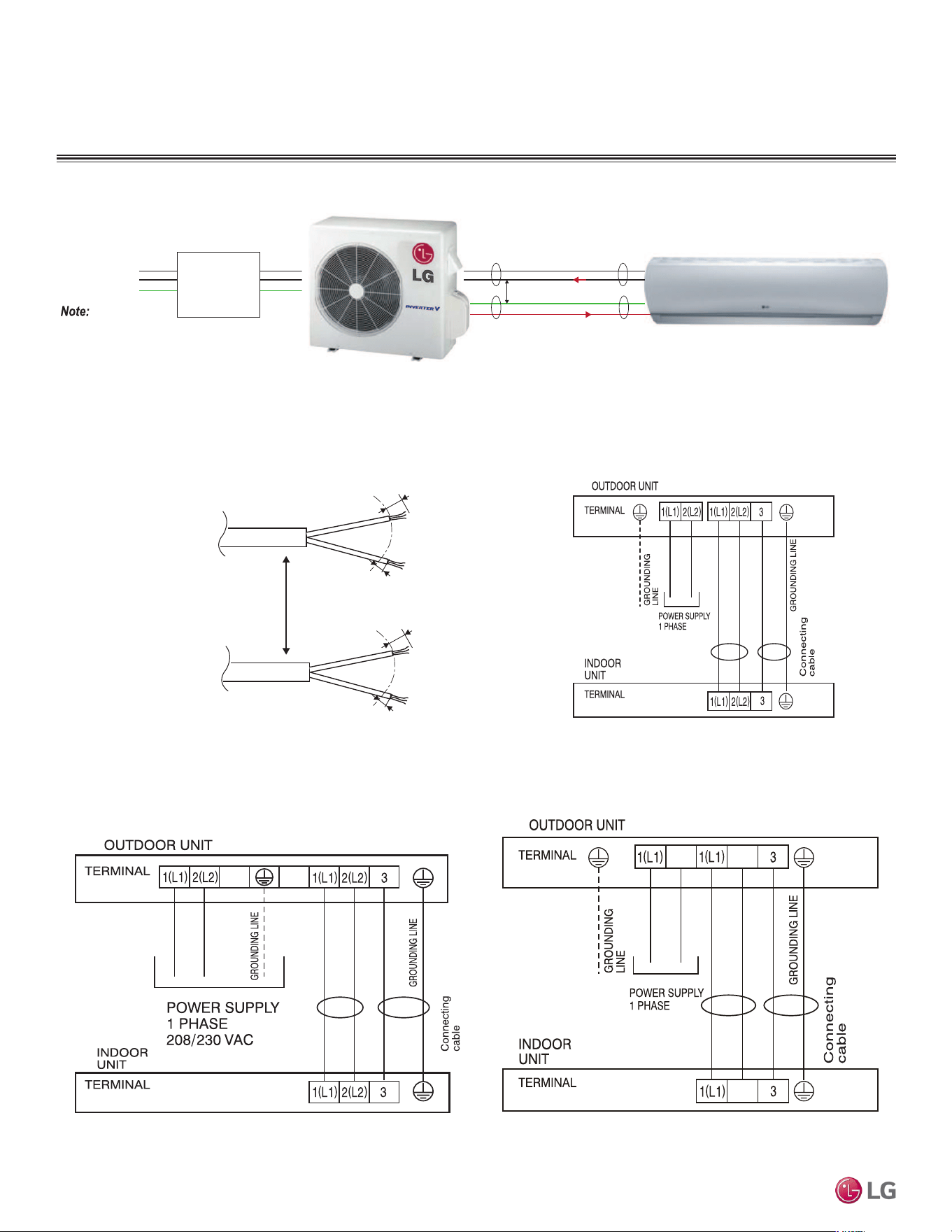
52
Single Zone Mega, Standard Eciency, and Mega 115V Wall Mounted Installation Manual
Due to our policy of continuous product innovation, some specifications may change without notification.
©LG Electronics U.S.A., Inc., Englewood Cliffs, NJ. All rights reserved. “LG” is a registered trademark of LG Corp.
ELECTRICAL SYSTEM INSTALLATION
Figure 82: Schematic of a Single Zone System When the Wiring is GREATER THAN 130 Feet.
Two-Conductor
Power Cable
GN/YL
GN/YL = (Ground, Yellow)
Two-Conductor
Communication /
Ground Cable
Separate At Least
Two (2) Inches
13/16"
7/16" ± 1/8"
1(L1)
2(L2)
13/16"
7/16" ± 1/8"
3
Figure 84: LS090HEV2, LS120HEV2, LS090HFV3, LS120HFV3 Power
/ Communication System Diagram For Wiring Lengths GREATER THAN
130 Feet.
Power
Supply
1(L1) (Power, L)
2(L2) (Neutral, N)
G (Ground)
Power Flow: L → N
Diagram is an example of communication and power
cables when the wiring is GREATER THAN 130 feet.
Terminals may be labeled differently depending on the model.
Outdoor and Indoor Unit appearances may vary depending on the model.
Communication Flow: Comm → N
3 (Communications)
GREATER THAN 130 feet: Must Separate Communications and Ground (G) Cable from the Power
(1[L1]) and Neutral (2[L2]) Cable at Least Two (2) Inches.
At Least Two (2) Inches
Figure 85: LS180HEV2, LS240HEV2, LS180HFV3, LS240HFV3 Power
/ Communication System Diagram For Wiring Lengths GREATER THAN
130 Feet.
Connections and Specications
Figure 83: Single Zone Outdoor Unit to Indoor Unit Wiring and Com-
munications Cable Diagram For Wiring Lengths GREATER THAN 130
Feet.
208/230 VAC
Figure 86: LS090-120HXV2 Power / Communication System Diagram
For Wiring Lengths GREATER THAN 130 Feet.
115 VAC
2(L2)
2(L2)
2(L2)

53
Electrical System Installation
Due to our policy of continuous product innovation, some specifications may change without notification.
©LG Electronics U.S.A., Inc., Englewood Cliffs, NJ. All rights reserved. “LG” is a registered trademark of LG Corp.
ELECTRICAL SYSTEM INSTALLATION
Controller Options
Single Zone Mega, Standard Efficiency, and Mega 115V Wall Mount systems include a wireless handheld
remote controller (Model No. AKB74955602). Optional LG-suppled wired controllers are available. See
“Functions, Controls, Options” in the Single Zone HEV2, HFV3, HXV2 Wall Mounted Engineering Manu-
al”, or contact an LG representative for more information.
Wireless Handheld Remote Controller features:
• Display Panel: Displays operation conditions.
• On / Off Button: Turns system operation on and off.
• Mode Button: Selects the operation mode: Cooling, Heating, Auto, Dry (Dehumidification), or Fan.
• Temp Up / Down Buttons: Adjusts the desired room temperature in the different modes.
• Fan Speed Button: Sets desired fan speed.
• Reset: Initializes the handheld remote control settings.
Wired Controller Connections
Optional controllers (see “Functions, Controls, Options”, in the Single Zone HEV2, HFV3, HXV2 Wall
Mounted Engineering Manual” or contact an LG representative for more information) can connect to the
Single Zone Mega, Standard Efficiency, and Mega 115V Wall Mount indoor units in one of two different
ways.
1. LG Wired Remote Extension Cable with Molex plug (PZCWRC1; sold separately) that connects to the
CN-REMO terminal on the indoor unit PCB.
2. Field-supplied controller cable that connects to the indoor unit terminal block (must be at least UL2547 or UL1007, and at least FT-6 rated
if local electric and building codes require plenum cable usage). Communication cable from indoor unit to remote controller(s) is to be 22
AWG, 3-conductor, twisted, stranded, unshielded. Wiring must comply with all applicable local and national codes.
Display
Screen
Button
*
*
*
RESET
Figure 87: AKB74955602 Wireless
Handheld Remote Controller.
Figure 88: PZCWRC1 LG Wired Remote Extension Cable.
Verify the connectors are properly inserted.
C/BOX Cable (Plug type)
Extension cable
To Indoor Unit
CN-REMO
Terminal
TEMP
FAN
SPEED
OPER
MODE
Figure 89: Wired Controller Connection on the Indoor Unit
Terminal Block (Appearances and Terminal Placement
Will Vary Depending on Model).
When using eld-supplied controller cable, make sure to connect the yellow to yellow
(communications wire), red to red (12V power wire), and black to black (ground wire)
terminals from the remote controller to the indoor unit terminal blocks.
Controller Options
Indoor Unit Terminal Block
1(L1) 2
GND
3
GRN /
YLW
BR
BL
RD
CN-REMO
CN-CC

54
Single Zone Mega, Standard Eciency, and Mega 115V Wall Mounted Installation Manual
Due to our policy of continuous product innovation, some specifications may change without notification.
©LG Electronics U.S.A., Inc., Englewood Cliffs, NJ. All rights reserved. “LG” is a registered trademark of LG Corp.
ELECTRICAL SYSTEM INSTALLATION
Indoor Unit Electrical Connections
Connecting Indoor Unit Electrical Wiring (HEV2, HFV3, and HXV2)
• Verify that main power to the unit is completely off before proceeding with these steps as there is a risk of electrical shock, bodily injury, and /
or death.
• Follow all safety and warning information outlined at the beginning and throughout this manual. Failure to do so will cause electrical shock,
bodily injury, and / or death.
1. The bottom panel must have already been removed. If it hasn’t
been removed, unsnap the bottom cover at its top left and right
sides (Location 1).
2. Unsnap each of the three (3) or four (4) small C-hooks located in
the middle of the bottom cover (Location 2). Number of C-hooks
present depends on model of indoor unit.
3. Lift the three (3) to four (4) hinges on the bottom cover up and
out of the channels molded to the left, right, and middle of the
indoor unit (Location 3). Number of hinges present depends on
model of indoor unit.
4. Set aside the bottom cover to re-install after all procedures are
complete.
5. Terminal block is located at the front bottom-right—hand side of the
indoor unit. To access the terminals, unscrew the metal control cover
screw (if applicable), and raise the metal control cover.
6. Using a JIS screwdriver, connect the cable terminals to the
terminal block. Ensure wire color and terminal number of the
indoor unit matches those of the outdoor unit. Refer to the wiring
diagram on the inside of the bottom cover.
7. Choice of the cable path out of the indoor unit and to the outdoor
unit depends on refrigerant piping / drain hose installation:
left side piping, following back of indoor unit; right side piping,
through the knockout hole; or rear piping.
• Follow all safety and warning information outlined at the beginning and throughout this manual. Failure to do so will cause unit failure.
• Connect the communication / connection (power) cable to the indoor unit by matching the terminals on the outdoor unit control board. Verify
the color of the wires at the outdoor unit, along with the terminal numbers, match those for the indoor unit.
• Images are representative; actual appearance will vary.
• Refer to the circuit diagram on the indoor unit bottom cover.
Figure 90: Steps to Removing
the Bottom Cover.
3
3
3
Figure 91: Removing the Bottom
Cover (Appearances Will Vary De-
pending on Indoor Unit Model).
Cover
1(L1) 2(L2) 3
Communication /
Connection
(Power) Cable
Figure 92: Location of the Indoor
Unit Terminal Block.
Figure 93: Terminal Cover Down. Figure 94: Terminal Cover Up.
LS090-120HEV2, LS090-120HFV3, and LS090-120HXV2 indoor
units and outdoor units have similar frames; however,
LS090-120HEV2 and LS090-120HFV3 systems require 208-
230V, 60Hz, 1ph power supply. LS090-120HXV2 systems
require 115V, 60Hz, 1ph power supply. Verify which system
is being installed. An incorrect power supply will result in
electric shock, re, physical injury, or death.

55
Electrical System Installation
Due to our policy of continuous product innovation, some specifications may change without notification.
©LG Electronics U.S.A., Inc., Englewood Cliffs, NJ. All rights reserved. “LG” is a registered trademark of LG Corp.
ELECTRICAL SYSTEM INSTALLATION
Slide the Metal Plate
Cover Up
Terminal Block
Connection Cable
Cable Clamp
1(L1) 2(L2) 3
Wiring When Piping is on the Left Side
Wiring When Piping is on the Right Side
Slide the Metal Plate
Cover Up
Terminal Block
Connection Cable
Cable Clamp
1(L1) 2(L2) 3
Figure 95: Cable / Refrigerant Piping / Drain Hose Installation Options.
Cable Installation When Piping is on the Left Side:
• Insert the communication / connection (power) cable through the
bottom of the indoor unit,
• Connect the terminals to the terminal block.
• Secure the cable onto the terminal block with the cable retainer.
• Secure the refrigerant piping, drain hose, and communication /
connection (power) cable together using cable ties and conduit, or
by the bundling method.
• Each wire must be securely attached to the terminal block.
• Ground cable must be longer than the other wires.
• Secure the cable onto the control board using a cable tie.
• Use a conduit to protect the cable / refrigerant piping from the
indoor unit to the outdoor unit.
Cable Installation When Piping is on the Right Side:
• Connect the terminals to the terminal block.
• Secure the cable onto the terminal block with the cable retainer.
• Secure the refrigerant piping, drain hose, and communication /
connection (power) cable together using cable ties and conduit, or
by the bundling method.
Position the drain hose at the bottom. Positioning the drain hose at the
top of the bundle can cause condensate to overow from the drain pan
in the inside of the indoor unit.
For more information on conduits or the bundling method, see the
Refrigerant Piping Connection section.
8. Reattach the metal control cover using the screw (if applica-
ble).
Indoor Unit Electrical Connections
LS090-120HEV2, LS090-120HFV3 and LS090-120HXV2 indoor units and outdoor units have similar frames; however,
LS090-120HEV2 and LS090-120HFV3 systems require 208-230V, 60Hz, 1ph power supply. LS090-120HXV2 systems require
115V, 60Hz, 1ph power supply. Verify which system is being installed. An incorrect power supply will result in electric shock,
re, physical injury, or death.
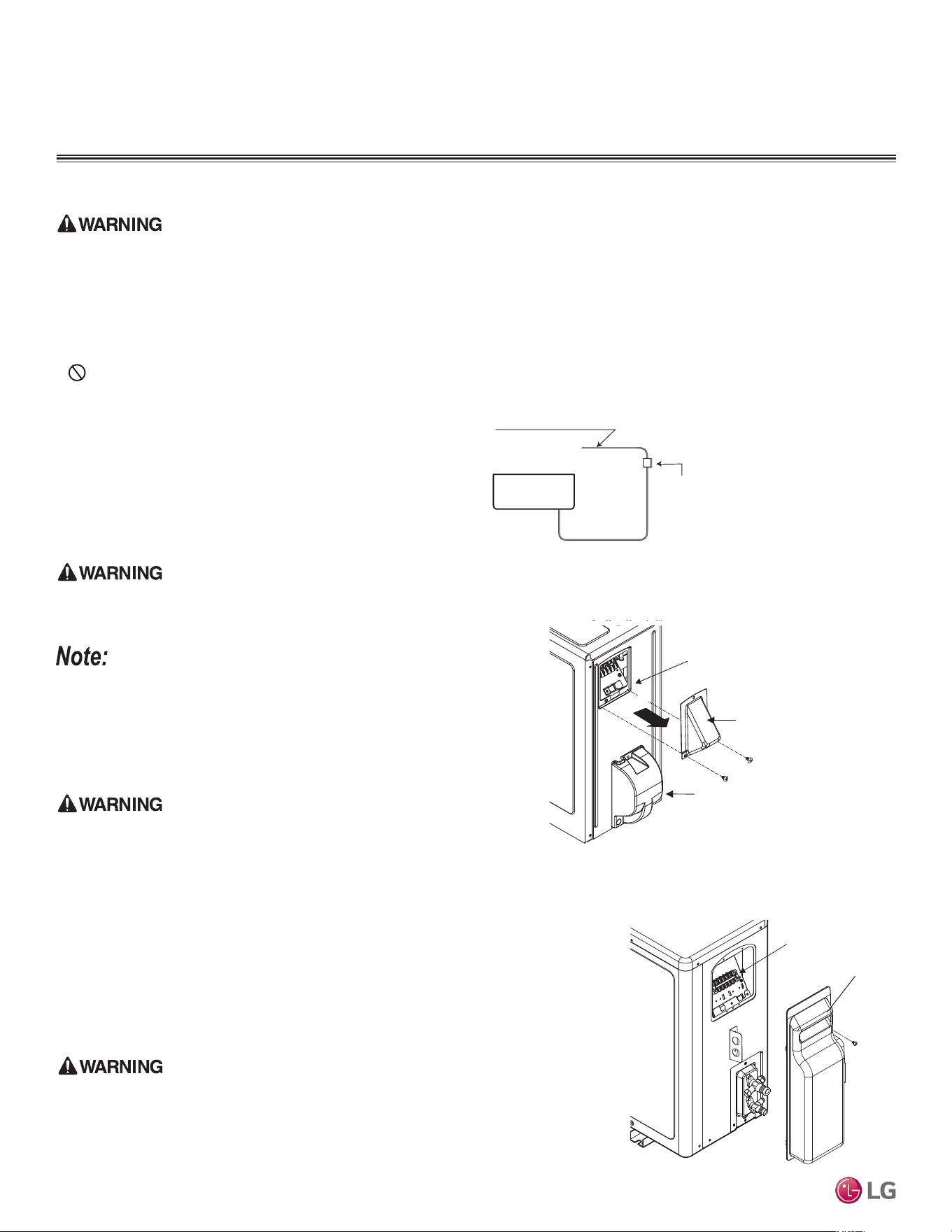
56
Single Zone Mega, Standard Eciency, and Mega 115V Wall Mounted Installation Manual
Due to our policy of continuous product innovation, some specifications may change without notification.
©LG Electronics U.S.A., Inc., Englewood Cliffs, NJ. All rights reserved. “LG” is a registered trademark of LG Corp.
ELECTRICAL SYSTEM INSTALLATION
Outdoor Unit Electrical Connections
Connecting Outdoor Unit Wiring
• Verify that main power is completely off and that no power is going through the Single Zone system before proceeding with these steps.
Follow all safety and warning information outlined at the beginning of this manual. Failure to do so will cause electric shock, bodily injury
and / or death.
• Per code, install a main indoor breaker, and an outdoor service disconnect that interrupts all power sources simultaneously. There is risk of
fire, electric shock, explosion, physical injury or death.
• Verify that the circuit breaker or some other emergency power cutoff device is in place before any power wiring is done to the system. Fail-
ure to do so will cause electric shock, bodily injury and / or death.
•
Never touch any power lines or live cables before all power is cutoff to the system. To do so will cause bodily injury or death.
1. Using a Phillips head screwdriver, remove the piping / control box
cover or control box cover (depends on model) from the outdoor
unit.
2. Inspect all wiring inside the chassis to be sure they are secure and
have not loosen during transportation and installation of the outdoor
unit. Inspect wires for damage or cracks.
Loose, damaged, or cracked wires will cause electric shock, bodily injury
and / or death.
Loose wires can cause the wiring to burn out, damaging the outdoor unit.
3. Confirm that electrical power supply capacity will be sufficient to
run the unit. Verify that a circuit breaker and service disconnect are
installed. See the Electrical table in the Product Data section for
details on electrical requirements.
Per code, install a main indoor breaker, and an outdoor service discon-
nect that interrupts all power sources simultaneously. There is risk of re,
electric shock, explosion, physical injury or death.
4. Confirm that the right gauge size is used for all wiring. Follow all
federal, state, and local codes related to wiring.
5. Guide the power wiring to the outdoor unit, and communications /
connection (power) cable from the outdoor unit to the indoor unit,
through the conduit holes on the outdoor unit or control box cover
(see images on the right and on the next page). Install conduits to
protect the wiring and cable.
Air
Conditioner
Main Power Source
Circuit Breaker
Use a circuit breaker
or time delay fuse
Figure 96: Circuit Breaker.
LSU180, 240HEV2
Terminal Block
Piping / Control
Box Cover
Figure 97: Accessing LSU090-120HEV2, LSU090-120HFV3, and
LSU090-120HXV2 Outdoor Unit Wiring Connections (Appearances Will
Differ Depending on Model).
Figure 98: Accessing LSU180-240HEV2 and LSU180-240HFV3
Outdoor Unit Wiring Connections.
Piping Connection
Cover
Outdoor Unit
Control Box
Cover
Terminal Block
LS090-120HEV2, LS090-120HFV3, and LS090-120HXV2 indoor units and outdoor
units have similar frames; however, LS090-120HEV2 and LS090-120HFV3 systems
require 208-230V, 60Hz, 1ph power supply, while LS090-120HXV2 systems require
115V, 60Hz, 1ph power supply. Verify which system is being installed. An incorrect
power supply will result in electric shock, re, physical injury, or death.

57
Electrical System Installation
Due to our policy of continuous product innovation, some specifications may change without notification.
©LG Electronics U.S.A., Inc., Englewood Cliffs, NJ. All rights reserved. “LG” is a registered trademark of LG Corp.
ELECTRICAL SYSTEM INSTALLATION
Do not install power wiring to the outdoor unit
and the communication / connection (power) cable
to the indoor unit in the same conduit. Use separate
conduits. Communication problems will occur.
Figure 99: Example of Conduit.
Connecting Outdoor Unit Wiring, continued.
6. Using a JIS screwdriver, connect wires as shown at right. See
also indoor unit wiring diagram found on its bottom cover, and
outdoor unit wiring diagram on the inside of its chassis cover.
• Each wire must be individually and securely attached to each
terminal.
Loose, damaged, or cracked wires will cause electric shock, bodily
injury and / or death.
Loose wires can cause the wiring to burn out, damaging the outdoor
unit.
• Secure wiring / cables with cable ties.
• Pay attention to the location / connection of the ground cable.
• Maintain a minimum of 1/4 inches of wire length from terminal block
to cable bundle.
7. When finished, reattach the piping / control box cover or con-
trol box cover (depends on model) to the outdoor unit with the
screws.
Figure 100: HEV2, HFV3, and HXV2 Outdoor Unit
Conduit Holes / Access Points.
Figure 101: Outdoor Unit Electrical Connections.
Outdoor Unit Electrical Connections
LS090-120HEV2, LS090-120HFV3 and LS090-120HXV2 indoor units and outdoor units have similar frames; however,
LS090-120HEV2 and LS090-120HFV3 systems require 208-230V, 60Hz, 1ph power supply. LS090-120HXV2 systems require
115V, 60Hz, 1ph power supply. Verify which system is being installed. An incorrect power supply will result in electric shock,
re, physical injury, or death.
LSU090-240HEV2, LSU090-240HFV3,
LSU090-120HXV2
LSU180-240HEV2 Outdoor Unit Terminal Block
LSU090-120HEV2 Outdoor Unit Terminal Block
LSU090-120HXV2 Outdoor Unit Terminal Block
LSU090-120HFV3 Outdoor Unit Terminal Block
LSU180-240HFV3 Outdoor Unit Terminal Block

58
Single Zone Mega, Standard Eciency, and Mega 115V Wall Mounted Installation Manual
Due to our policy of continuous product innovation, some specifications may change without notification.
©LG Electronics U.S.A., Inc., Englewood Cliffs, NJ. All rights reserved. “LG” is a registered trademark of LG Corp.
FINAL INSTALLATION PROCEDURES
Triple Leak / Pressure Test
After the refrigerant piping installation is complete, perform a triple leak / pressure test. Triple leak / pressure test is performed between the
outdoor unit and indoor unit to verify that refrigerant can flow through the system without danger of leaks or pressure losses. Air and moisture
that is left in the piping can lead to undesirable results and can cause damage to the system. It is important to go through a complete leak /
pressure cycle to be sure that the refrigerant piping is cleared out. This process will have to be repeated if any air or moisture be is found to
remain in the piping.
• Pressure in the system can rise.
• Operating current can rise.
• Inefficient cooling or heating mode capability.
• Moisture in the refrigerant circuit will freeze and block capillary
tubing.
• Water can lead to corrosion of parts in the system.
Insufcient or incorrectly done air purging will lead to the following:
DANGER
Using combustible gases, including oxygen will result in re or explosion, resulting in personal injury or death. Use inert gas (medical-grade dry
nitrogen) when checking leaks, cleaning, installing/repairing pipes, etc. The use of an 800 psig or higher nitrogen regulator is required for safety.
• Never perform the leak test using refrigerant.
• To avoid nitrogen entering the refrigerant system in a liquid state, the top of the cylinder
must be higher than its bottom (used in a vertical standing position) when the system is
pressurized.
• Use only a leak-free gauge manifold set.
• Piping system must not be pressured to more than 550 psi. Pressures greater than 550 psi
will damage the piping system and cause unit malfunction.
Triple Leak / Pressure Check Procedure
1. After the refrigerant piping installation is complete, open the isolation ball valves, if any,
that will have been included in the piping system.
2. Verify that both the liquid and gas (vapor) suction line outdoor unit service ports are
closed, and the stem head access caps are tight. The leak / pressure check is to be
performed only to the refrigerant piping system and the connected indoor unit.
3. Remove the cap on the gas (vapor) suction line Schrader port. Connect the (medi-
cal-grade dry) nitrogen cylinder regulator to a gauge manifold, then connect the gauge
manifold to the gas (vapor) suction Schrader port on the service port.
4. Perform the leak / pressure check at 150 psig for fifteen (15) minutes (standing pressure
check).
5. Perform the leak / pressure check at 300 psig for thirty (30) minutes (standing pressure
check).
6. Perform the leak / pressure check at 550 psig for one (1) hour to make sure the piping
system is leak-free. After the gauge reading reaches 550 psig, isolate the system by first closing the gauge manifold, then close the nitro-
gen cylinder valve. Check the flared (and any brazed connections) for leaks by applying a bubble solution to all joints.
The bubble solution must be a solution designed for refrigerant leak testing. Common soap solution must never be used on refrigerant piping as
those contain chemicals that could corrode copper and brass, and cause product malfunction.
Triple Leak / Pressure Test
Figure 102: Outdoor Unit Service Valves. (Ap-
pearances Will Vary Depending on Model.)
Figure 103: Triple Leak / Pressure Test Diagram.
Indoor Unit
Outdoor Unit
Gauge Manifold
Charge Hose
Nitrogen Gas
Tank (Upright
Position)
Refrigerant
Piping
Micron
Gauge
Connected to Shrader Valve
on Gas (Vapor) Service Port
Gas (Vapor)
Piping
Liquid Piping
Cap
2-way valve(Close)
3-way valve(Close)
Two-way Valve (Closed)
Three-way Valve (Closed)
Schrader Port (Open)

59
Final Installation Procedures
Due to our policy of continuous product innovation, some specifications may change without notification.
©LG Electronics U.S.A., Inc., Englewood Cliffs, NJ. All rights reserved. “LG” is a registered trademark of LG Corp.
FINAL INSTALLATION PROCEDURES
Triple Leak / Pressure and Deep Evacuation Tests
Deep Evacuation Procedure
After the leak / pressure check is complete, it is required that a deep evacuation procedure is be performed to the refrigerant piping and the
connected indoor unit. Deep evacuation must be performed through the gas (vapor) suction line Schrader port on the outdoor unit service
port.
The deep evacuation procedure is required for Single Zone systems. A triple evacuation procedure seen on the following pages is a best practices
recommendation for Single Zone systems.
For faster evacuation, the Schrader core can be removed, and an auxiliary service port can used. Make sure to re-install the original Schrader core
before operating the system.
• Deep evacuate through just the gas (vapor) suction Schrader port on the outdoor unit service port.
• The outdoor unit service valves must remain closed and the stem head access caps tight. Do not open the outdoor unit service valves
and release the factory refrigerant charge until trim charge is complete, and the system is ready to operate.
• Any field-installed ball valves in the refrigerant system (if used) must be open to ensure all piping is free and clear for deep evacuation on
all piping and the connected indoor unit.
Triple Leak / Pressure Check Procedure, continued.
7. If the pressure does NOT drop for one (1) hour, the system passes the test.
8. If the pressure drops, there is a leak and it must be found. Remove the bubble solution with a clean cloth, repair the leak(s), and perform
the leak / pressure check again.
9. After the system has been thoroughly tested and no leaks are found, depressurize by loosening the charging hose connector at the nitro-
gen cylinder regulator. When system pressure returns to normal, completely disconnect the charging hose from the cylinder, and release
the nitrogen charge from all refrigerant piping. Wipe off any remaining bubble solution with a clean cloth.
• Do not apply power to the system before performing the deep evacuation procedure. There is a possibility that the EEV valve will close
and isolate sections of the piping system, making the deep evacuation procedure inconclusive.
• Never perform evacuation using refrigerant.
• Use only a vacuum pump that can reach 500 microns, vacuum rated hoses or copper tubing, and a leak-free gauge manifold set.
• Use only new vacuum pump oil from a properly sealed (unopened) container, and change oil in pump before EVERY use.
• Subsequent oil changes will be necessary after several hours of continuous operation; have extra oil on hand.
• Use a quality micron gauge in good operating order and install as far away from pump as possible.
Deep Evacuation Procedure Steps
1. If this procedure is performed shortly after the leak / pressure test, the cap and core on the gas (vapor) suction Schrader port must have
already been removed, and the manifold must already be connected. If the procedure was not performed shortly after the leak / pressure
test, make sure to remove the cap and core on the gas (vapor) suction Schrader port. Verify that the service valves on the outdoor unit
are closed, and the stem head access caps are tight.
2. Connect the gauge manifold along with the vacuum pump to the gas (vapor) suction Schrader port (with core removed) using a vacuum
hose. Open the gauge manifold and the vacuum pump valves.

60
Single Zone Mega, Standard Eciency, and Mega 115V Wall Mounted Installation Manual
Due to our policy of continuous product innovation, some specifications may change without notification.
©LG Electronics U.S.A., Inc., Englewood Cliffs, NJ. All rights reserved. “LG” is a registered trademark of LG Corp.
FINAL INSTALLATION PROCEDURES
Deep Evacuation Procedure, continued.
3. Evacuate to static micron level ≤500 for at least one (1) hour.
4. Micron level must remain ≤500 for two (2) hours. If the vacuum gauge rises and stops, the
system may contain moisture; therefore, it will be necessary to repeat the steps of vacuum
break and drying.
5. After maintaining the system in vacuum for two (2) hours, check if the vacuum gauge rises or
not. If it doesn’t rise, then the system is properly evacuated.
6. Close manifold gauges.
7. Shut the valves before turning off and disconnecting the vacuum pump.
Figure 104: Evacuation Procedure Diagram.
Outdoor Unit
Gauge Manifold
Vacuum Pump
Close
Indoor Unit
Refrigerant
Piping
Connected to
Shrader Valve
on Gas (Vapor)
Service Port
Vacuum Hose
Open
Micron
Gauge
Triple Evacuation Procedure
After the leak / pressure check is complete, it is a best practices recommendation that a triple
evacuation procedure is performed to the refrigerant piping and the connected indoor unit. Triple
evacuation must be performed through the gas (vapor) suction Schrader port on the outdoor unit
service port.
The deep evacuation procedure is required for Single Zone systems. The triple evacuation procedure is a
best practices recommendation for Single Zone systems.
For faster evacuation, the Schrader core can be removed, and an auxiliary service port can used. Make sure to re-install the original Schrader core
before operating the system.
• Evacuate through just the gas (vapor) suction Schrader port on the outdoor unit service port.
• The outdoor unit service valves must remain closed and the stem head access caps tight. Do not open the outdoor unit service valves
and release the factory refrigerant charge until trim charge is complete, and the system is ready to operate.
• Any field-installed ball valves in the refrigerant system (if used) must be open to ensure all piping is free and clear for evacuation on all
piping and connected indoor unit.
• Never perform evacuation using refrigerant.
• Use only a vacuum pump that can reach 500 microns, vacuum rated hoses or copper tubing, and a leak-free gauge manifold set.
• Use only new vacuum pump oil from a properly sealed (unopened) container, and change oil in pump before EVERY use.
• Subsequent oil changes will be necessary after several hours of continuous operation; have extra oil on hand.
• Use a quality micron gauge in good operating order and install as far away from pump as possible.
Deep Evacuation and Triple Evacuation Tests
61
Final Installation Procedures
Due to our policy of continuous product innovation, some specifications may change without notification.
©LG Electronics U.S.A., Inc., Englewood Cliffs, NJ. All rights reserved. “LG” is a registered trademark of LG Corp.
FINAL INSTALLATION PROCEDURES
Triple Evacuation Procedure Steps
1. If this procedure is performed shortly after the leak / pressure test, the cap and core on the gas (vapor) suction Schrader port must have
already been removed, and the manifold must already be connected. If the procedure was not performed shortly after the leak / pressure
test, make sure to remove the cap and core on the gas (vapor) suction Schrader port. Verify that the service valves on the outdoor unit
are closed, and the stem head access caps are tight.
2. Connect the gauge manifold along with the vacuum pump to the gas (vapor) suction Schrader port (with core removed) using a vacuum
hose. Open the gauge manifold and the vacuum pump valves.
After the vacuum pump is rst operated, if hoses, manifold, and vacuum valves are leak free (and oil is not moisture laden), the gauge must read
<100 microns within one (1) minute.
Do not proceed if the gauge does not read <100 microns within one (1) minute. There is a leak in the hose, gauge manifold, or vacuum valve,
and the equipment must be replaced.
3. Operate the vacuum pump and evacuate the system to the 2,000 micron level. Isolate the pump by closing the manifold gauges and the
vacuum pump valve, and then watch the micron level. Micron level will rise a bit, but MUST eventually stop rising for fteen (15) minutes.
• If the micron level DOES NOT stop rising, there is a leak, and the leak test must be performed again.
• If the micron level DOES rise above 2,000 micron, re-open the manifold gauges and the vacuum pump valve and continue evacuation back
down to 2,000 micron level.
• If the micron level holds at 2,000 micron, continue to step 4.
4. Break vacuum with 50 psig nitrogen purge for an appropriate amount of time (this is to “sweep” moisture from piping).
5. Purge nitrogen from the system until the pressure drops down to 1 to 3 psig.
6. Evacuate to 1,000 micron level. Isolate the pump by closing the manifold gauges and the vacuum pump valve, and then watch the micron
level. Micron level will rise a bit, but MUST eventually stop rising for fifteen (15) minutes.
• If the micron level DOES NOT stop rising, there is a leak, and the leak test must be performed again.
• If the micron level DOES rise above 1,000 micron, re-open the manifold gauges and the vacuum pump valve, and continue evacuation back
down to 1,000 micron level.
• If the micron level holds at 1,000 micron, continue to step 7.
7. Break vacuum with 50 psig nitrogen purge for an appropriate amount of time.
8. Purge nitrogen from the system until the pressure drops down to 1 to 3 psig.
9. Evacuate to static micron level ≤500 for at least one (1) hour.
10. Micron level must remain ≤500 for two (2) hours. If the vacuum gauge rises and stops, the system may contain moisture; therefore, it will
be necessary to repeat the steps of vacuum break and drying.
11. After maintaining the system in vacuum for two (2) hours, check if the vacuum gauge rises or not. If it doesn’t rise, then the system is
properly evacuated.
12. Close manifold gauges.
13. Shut the valves before turning off and disconnecting the vacuum pump.
Triple Evacuation Test
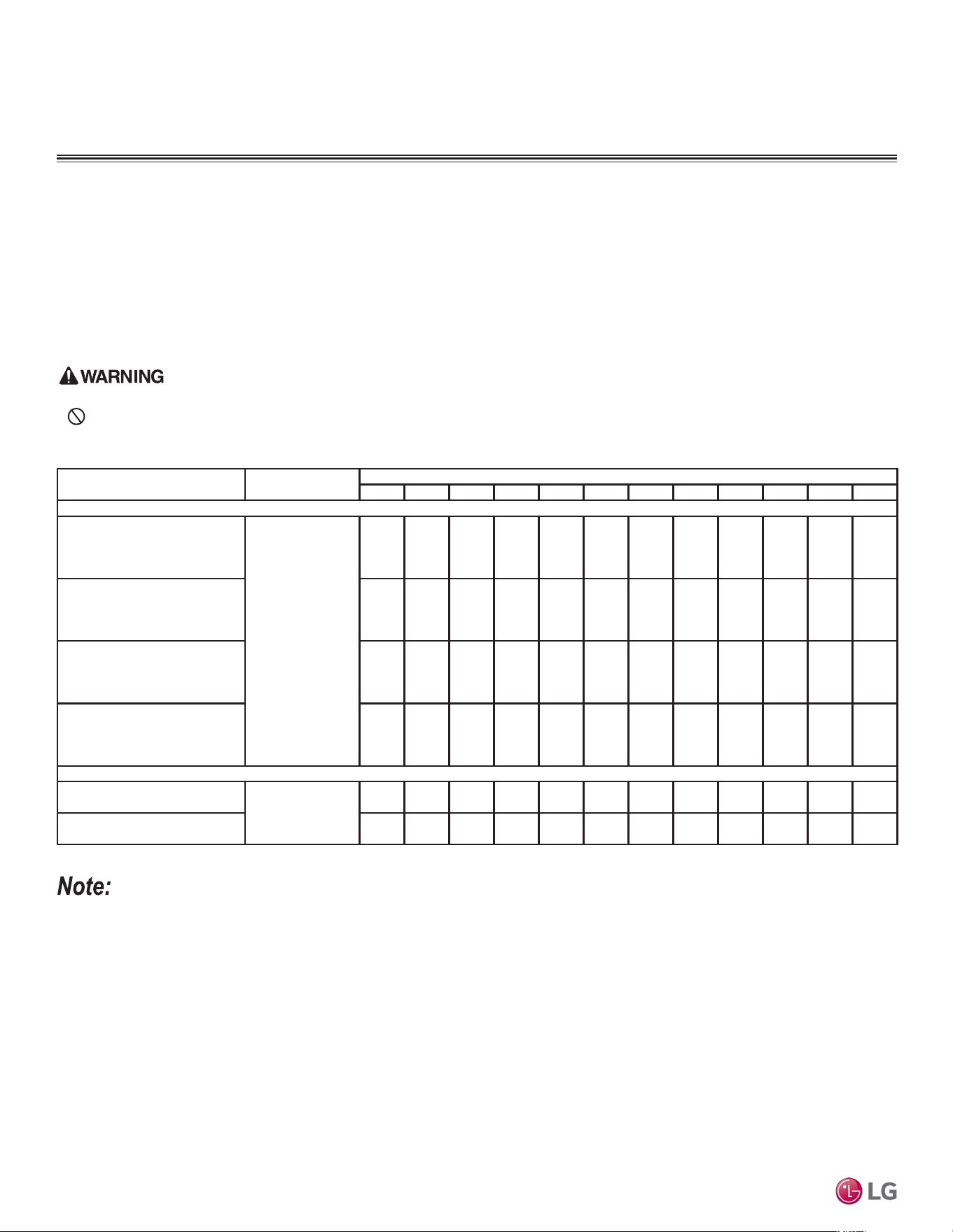
62
Single Zone Mega, Standard Eciency, and Mega 115V Wall Mounted Installation Manual
Due to our policy of continuous product innovation, some specifications may change without notification.
©LG Electronics U.S.A., Inc., Englewood Cliffs, NJ. All rights reserved. “LG” is a registered trademark of LG Corp.
FINAL INSTALLATION PROCEDURES
Refrigerant Trim Charge
The single zone system will need an additional refrigerant charge if the installed piping lengths are greater than the “piping length (no
additional refrigerant, ft.) specification” listed in the product tables. See the product sections in the engineering and installation manuals. The
additional refrigerant charge can be calculated manually using the information in the engineering and / or installation manuals, or by LATS.
1. Keep the outdoor unit service values closed while adding the trim charge to the system. See the specification tables in the front of this
installation manual for base charge, and see below for the correct additional refrigerant trim charge amounts for each system.
2. Charge through just the gas (vapor) suction Schrader port.
• Follow all guidelines when handling refrigerant.
• Never inhale or handle refrigerant directly. Doing so will cause bodily injury.
Table 22: Single Zone Mega, Standard Efciency, and Mega 115V Refrigerant Piping System Additional Refrigerant Charge.
Refrigerant Trim Charge, Finishing the Job
Model Numbers
Refrigerant Piping Length (ft.)
16.4 24.6 32.8 41.0 49.2 65.6 82.0 98.4 114.8 131.2 147.6 164.0
Mega, Standard Efficiency Models
LS090HEV2
(LSN090HEV2 / LSU090HEV2)
LS090HFV3
(LSN090HFV3 / LSU090HFV3)
Additional
Refrigerant
Charge (oz.)
0 0 1.8 3.6 5.4 - - - - - - -
LS120HEV2
(LSN120HEV2 / LSU120HEV2)
LS120HFV3
(LSN120HFV3 / LSU120HFV3)
0 0 1.8 3.6 5.4 - - - - - - -
LS180HEV2
(LSN180HEV2 / LSU180HEV2)
LS180HFV3
(LSN180HFV3 / LSU180HFV3)
0 0 2.1 4.3 6.4 10.7 - - - - - -
LS240HEV2
(LSN240HEV2 / LSU240HEV2)
LS240HFV3
(LSN240HFV3 / LSU240HFV3)
0 0 2.1 4.3 6.4 10.7 - - - - - -
Mega 115V Models
LS090HXV2
(LSN090HXV2 / LSU090HXV2)
Additional
Refrigerant
Charge (oz.)
0 0 1.8 3.6 5.4 - - - - - - -
LS120HXV2
(LSN120HXV2 / LSU120HXV2)
0 0 1.8 3.6 5.4 - - - - - - -
• Capacity is based on standard length.
• Equivalent Pipe Length = Actual Pipe Length + Number of Bends x 0.3.
• Additional Refrigerant Charge Calculation : X (g) = [ (Refrigerant Pipe Length) - (No Charge Pipe Length) ] × (Additional Refrigerant).
• There is no need to add refrigerant if equivalent pipe is less than the “piping length with no additional refrigerant” in the table above.

63
Final Installation Procedures
Due to our policy of continuous product innovation, some specifications may change without notification.
©LG Electronics U.S.A., Inc., Englewood Cliffs, NJ. All rights reserved. “LG” is a registered trademark of LG Corp.
FINAL INSTALLATION PROCEDURES
Finishing the Job
Finishing the Job
After the Triple Leak and Evacuation (and refrigerant trim charge, if any) procedures have been performed, follow the steps below to open
the refrigerant lines.
1. Verify that the auxiliary service port is removed (if used in the Evacuation procedure) and the original Schrader core was re-installed on
the gas (vapor) suction service port.
2. The service ports are a back-seated type with a right hand thread. Remove the service valve caps on both the gas (vapor) suction and the
liquid service ports.
3. Using an appropriately sized Allen wrench, fully open the valves on both the gas (vapor) suction and the liquid service ports by turning the
valve stem counterclockwise.
4. Turn until the valve stem is out, stops, and the valve is completely backseated.
Do not apply excessive force.
5. Securely replace service port caps on both the gas (vapor) suction and the liquid using an adjustable wrench.

64
Single Zone Mega, Standard Eciency, and Mega 115V Wall Mounted Installation Manual
Due to our policy of continuous product innovation, some specifications may change without notification.
©LG Electronics U.S.A., Inc., Englewood Cliffs, NJ. All rights reserved. “LG” is a registered trademark of LG Corp.
FINAL INSTALLATION PROCEDURES
Reattach the indoor unit bottom cover after all other installation
procedures are complete.
1. If ON, shut power OFF to the system.
2. At the bottom of the bottom cover, insert the three (3) to four (4)
hinges into the channels molded to the left, right, and middle of
the indoor unit (Location 1). Number of hinges present depends
on model of indoor unit.
3. After all hinges are secure, match the three (3) or four (4) small
C-hooks located in the middle of the bottom cover (Location 2)
to their sockets on the indoor unit. (Number of C-hooks present
depends on model of indoor unit.) On the outside of the bottom
cover, securely snap the C-hooks in place at each location using
the heel of the palm.
4. Match the snaps at the top left and right sides of the bottom
cover to their sockets, and push to lock the bottom cover to the
indoor unit (Location 3).
5. Verify the bottom cover is securely installed by pushing the bot-
tom cover to the indoor unit at all attachment locations.
Figure 105: Close Up of Bottom Cover Connections (Appearances Will
Vary Depending on Indoor Unit Model).
Hinge
Top Snaps
C-Hooks
Reattaching the Indoor Unit Bottom Cover (HEV2, HFV3, and HXV2)
Figure 106: Inserting the Bottom Cover Hinges into the Indoor Unit Chan-
nels (Step 2).
To prevent bending the bottom cover (and subsequent damage), assem-
ble the bottom cover correctly.
Figure 107: Securing the Bottom Cover C-hooks to
the Indoor Unit Sockets (Step 3).
3
3
Figure 108: Snapping the Top Left and Right
Sides (Step 4).
Figure 109: Checking that All Attachment Loca-
tions Are Secure (Step 5).
3
3
Reattaching the Indoor Unit Bottom Cover

65
Final Installation Procedures
Due to our policy of continuous product innovation, some specifications may change without notification.
©LG Electronics U.S.A., Inc., Englewood Cliffs, NJ. All rights reserved. “LG” is a registered trademark of LG Corp.
FINAL INSTALLATION PROCEDURES
Air Filter Assembly
1. Turn power OFF to the system.
2. Holding the air filter by its handles, match the hooks and grooves
on the air filter to the hooks and grooves at the top-back of the
indoor unit. (Number of hooks and grooves present depends on
model of indoor unit.)
3. Match the air filter bars and grooves to the grooves and hooks at
the top-front of the indoor unit.
4. Use thumbs to gently snap the air filter to the indoor unit where
the top-front bars, grooves, and hooks are located.
5. Check the sides of the front grille to verify the air filter is assem-
bled correctly.
6. Turn power back on to the system.
• It is easier to assemble and disassemble the air filter if standing on
a ladder looking down at the top of the indoor unit.
• Do not bend the air filter; this damages it.
• If the air filter is not assembled correctly, dust and other substances
will enter the indoor unit.
2. Lifting the Air Filter by the Handles.
3. Disassembling the Air Filter.
Air Filter Disassembly and Assembly (HEV2, HFV3,
and HXV2)
Air Filter Disassembly
1. Turn power off to the system.
2. Find the handles located at the top-front of the air filter molded into the plastic frame support.
3. Lift handles slightly up and out to remove the air filter.
2. Matching Hooks to Top-Back Grooves.
Three (3) Top-Back Hooks to Grooves.
Four (4) Top-Back Hooks to Grooves.
3. Location of Two (2) Top-Front Bars.
Example of Indoor Unit Hook to Air Filter Groove.
4. Securing the Air Filter on the Indoor Unit.
5. Checking the Sides for Correct Air Filter Assembly.
Figure 110: Disassembling the Air Filter
(Appearances Will Vary Depending on
Indoor Unit Model).
Figure 111: Assembling the Air Filter (Appearances Will Vary Depending
on Indoor Unit Model).
Air Filter Disassembly and Assembly

66
Single Zone Mega, Standard Eciency, and Mega 115V Wall Mounted Installation Manual
Due to our policy of continuous product innovation, some specifications may change without notification.
©LG Electronics U.S.A., Inc., Englewood Cliffs, NJ. All rights reserved. “LG” is a registered trademark of LG Corp.
FINAL INSTALLATION PROCEDURES
Installing Batteries into the Handheld Remote Controller
For information on using the handheld remote controller, refer to its owner’s manual.
1. The remote controller needs two AAA (1.5V) batteries for operation. Remove the battery cover
from the back of the remote controller by pushing the tab down in the direction seen at right.
2. Insert the two new batteries.
• Align batteries by the (+) and (-) sides.
• The interior battery compartment of the remote controller will have clear markings for the (+)
and (-) placement.
3. Verify that the batteries have clicked into the compartment and are firmly engaged with the
contacts on either side of them.
4. Reattach the back cover of the remote controller.
5. Proceed with powering on the remote controller and use as needed. Remove the batteries if system won’t be used for an extended time.
Figure 112: Installing the Remote Controller
Batteries.
Battery Cover
Battery Cover Tab
1. Slide battery cover
tab down. Lift cover
and set aside.
2. Insert Batteries.
Performance Evaluation
Operate the unit in heating and / or cooling, depending on outdoor conditions, for 15 to 20
minutes, then check the system refrigerant charge (feature availability depends on model):
1. Measure the pressure of the gas (vapor) suction service valve. See optimum psig in table
at right.
2. Measure the air temperature from both the inlets and outlets.
3. Verify the difference between the inlet and outlet temperatures is >14.4°F.
4. The air conditioner is now ready to use.
Outside Ambient
Temperature
Gas (Vapor) Service
Valve Pressure
95°F 120~135 psig
Test Run
After all installation procedures are complete, the system is ready for a test run. Follow the guide-
lines below.
1. Check that all drain piping, refrigerant piping, and wiring / cables are properly connected.
2. Check that both the gas (vapor) suction and liquid refrigerant piping service valves are fully open.
3. Install the batteries into the handheld remote controller (see above).
4. Turn on the power to the outdoor unit, and press and hold the On / Off button for three (3) to five
(5) seconds; this switches the system to test operation mode.
5. The system will operate in cooling with maximum air flow for 18 minutes before returning to the factory default setting. While system oper-
ates in the test operation mode, note any issues that occur, and fix as necessary.
Figure 113: Test Operation Mode.
On / Off Button
• If all modes can’t be tested all at one time, testing must be performed later when weather
conditions permit.
• If the actual pressure is higher than shown, the system is most likely overcharged, and charge
must be removed. If the actual pressure is lower than shown, the system is most likely under-
charged, and charge must be added.
Table 23: Gas Side Pressure at Optimum Condi-
tion When System is in Cooling.
Discharge
Temperature
Discharge
Air
Inlet Temperature
Figure 114: Performance Evaluation Measure-
ment Locations.
Installing Batteries, Test Run, Performance Evaluation

67
Final Installation Procedures
Due to our policy of continuous product innovation, some specifications may change without notification.
©LG Electronics U.S.A., Inc., Englewood Cliffs, NJ. All rights reserved. “LG” is a registered trademark of LG Corp.
FINAL INSTALLATION PROCEDURES
Installer Mode
It will be necessary to switch to Installer mode if the system needs to operate in Heating Only or
Cooling Only modes, or the Pump Down procedure needs to be performed.
To Enter Installer Mode:
1. Press the Reset and “A” buttons. A very slender tool is needed to access the Reset button.
2. Set the code by pressing the Up and Down Temperature buttons, and then press the ON / OFF
button. The Up Temperature button changes the code on the ten (10) digit; the Down Temperature
button changes the code on the one (1) digit.
Press
SETUP
Figure 115: Using the Handheld Con-
troller to Change System to Installer
Mode.
Installer Mode, Cooling Only Mode
• After the system is in Installer mode (with Cooling Only mode initiated), automatic operation is suspended.
• After Cooling Only mode is disabled, the system will return to normal operation.
• Installer mode cannot be entered if the unit is running. The system must be completely OFF.
• All Installer code numbers must be entered when system is OFF.
• WLAN Module’s communication time will lag by about one (1) minute after unit is turned back on, and in normal operating mode.
• Entire lock or Mode lock cannot be set if heating or automatic operation is set through a central controller.
Disabling Cooling Only Mode
After Pump Down procedure has been performed, Cooling Only
mode will need to be disabled, and the system will need to be re-
turned to normal operating mode.
1. Supply power to the system, but system must be OFF with all
functions inactive.
2. Enter the Installer mode.
3. Set code to 43 for HEV2, HFV3 systems, or 46 for HXV2
systems.
4. Press ON / OFF button and select the code number 43 for
HEV2, HFV3 systems, or 46 for HXV2 systems. Unit will beep to
acknowledge that code has been received.
5. Turn off power for a minimum of 30 seconds.
6. Turn power back on to system.
Enabling Cooling Only Mode
Before running the Pump Down procedure, the unit must be
switched to Cooling Only mode. To be able to run Cooling Only
mode, the unit must be changed to Installer mode (see previous
page for instructions).
1. Supply power to the system, but system must be OFF with all
functions inactive.
2. Enter the Installer mode.
3. Set code to 45 for Mega (HEV2), Standard Efficiency (HFV3),
and Mega 115V (HXV2).
4. Press ON / OFF button and select the code number 45. Unit will
beep to acknowledge that code has been received.
5. Turn off power for a minimum of 30 seconds.
6. Turn power back on to system.

68
Single Zone Mega, Standard Eciency, and Mega 115V Wall Mounted Installation Manual
Due to our policy of continuous product innovation, some specifications may change without notification.
©LG Electronics U.S.A., Inc., Englewood Cliffs, NJ. All rights reserved. “LG” is a registered trademark of LG Corp.
FINAL INSTALLATION PROCEDURES
Perform Pump Down procedure in the Cooling Only mode.
Pump Down Procedure
This procedure is performed when the refrigerant piping system is serviced. Pumping down collects all the refrigerant in the outdoor unit
without losing any charge. Always adhere to and be familiar with local codes regarding the handling of refrigerant.
The system must operate in Cooling Only mode to proceed with the pump down procedure. If needed, refer to the previous sections for prop-
er steps to place the unit into Cooling Only mode.
1. Turn off the unit’s power switch. Connect a low-pressure gauge manifold hose to the charge port on the gas (vapor) suction service
valve.
2. Open the gas (vapor) suction service valve halfway, and purge the air in the manifold hose using the refrigerant.
3. Fully close the liquid piping service valve.
4. Turn on the unit’s power switch and start the Cooling Only mode operation.
5. Observe the pressure gauge reading. When it changes 14.2 to 7.1 psig, fully close the gas line valve and then immediately turn the unit
off. Pump down procedure is complete and all refrigerant will be collected into the outdoor unit.
•
Never inhale or handle refrigerant directly. Doing so will cause bodily harm and injury.
• After pump down, power must be turned off before the hose is removed. If the system is operated without the hose connected, air inside the
compressor will cause the pressure to increase, and possibly cause an explosion and physical injury.
Pump Down Procedure

69
Troubleshooting
TROUBLESHOOTING
Due to our policy of continuous product innovation, some specifications may change without notification.
©LG Electronics U.S.A., Inc., Englewood Cliffs, NJ. All rights reserved. “LG” is a registered trademark of LG Corp.
LG SIMS - Self Diagnosis Functions
The SIMs WLAN module and the smart phone app together provide monitoring and trouble-
shooting capability for LG Duct Free Systems. SIMs function only with LG Duct Free products.
LG SIMs can also be used with Single Zone one-to-one configurations such as the Single
Zone Wall Mount systems. SIMs app is available for Apple
®
iPhone
®
iOS or Android™ smart
phone operating systems. Download the latest version from the App Store (iPhone iOS) or
Google Play™ store (Android). (Apple and iPhone are trademarks of Apple Inc., registered in
the U.S. and other countries. Android and Google Play store are trademarks of Google LLC.)
SIMs can display and graph operational data for the air conditioner system including the
indoor unit and the outdoor unit. SIMs also displays error codes and a troubleshooting guide.
A full copy of the LG SIMs Smart Inverter Monitoring System User’s Manual is available on
the www.lghvac.com website.
To use SIMs, you must be a trained HVAC service technician familiar with variable refrig-
erant flow (VRF) systems in general, and with LG’s Duct Free System products. You must
understand the inverter air conditioning operation cycle, the meaning of the data displayed by
SIMs, and how to use the data to troubleshoot the system.
• The Duct Free System air conditioning system must run for at least
15–20 minutes before data collected by SIMs is valid for trouble-
shooting.
• The free SIMs app must be correctly installed on the smart phone
before using SIMs.
• Some outdoor units have an LGMV extension cable accessed by
removing the side handle cover. If the outdoor unit does not have
this extension cable, access the LGMV connector by removing the
top cover of the outdoor unit.
High voltages capable of causing death are used in this equipment. Out-
door unit power remains connected during this procedure. Take extreme
caution not to touch electrical components or connections. Failure to
observe this warning can result in death or severe injury.
Figure 116: LG SIMs App and WLAN Module.
Figure 117: SIMs WLAN Module to DFS System Example.
Figure 118: SIMs App Main Info Screen
SIMs App Main Info Screen
The main screen is the first screen displayed after wireless connec-
tion is established. Tap the Main Info tab to display current readings
regarding the indoor and outdoor unit(s). The Operational Info area
of the screen will show active functions or modes by illuminating the
light to the right of the function.
Additional Help information can be accessed by tapping the Help
Menu buttons at the bottom of this screen.
Operational
Information
AC Cycle
Information on
Main Info Tab
Help Menu
(File is Factory Use Only)
LG SIMs
WLAN Module
LG SIMs App
on Smart Phone

70
Single Zone Mega, Standard Eciency, and Mega 115V Wall Mounted Installation Manual
Due to our policy of continuous product innovation, some specifications may change without notification.
©LG Electronics U.S.A., Inc., Englewood Cliffs, NJ. All rights reserved. “LG” is a registered trademark of LG Corp.
TROUBLESHOOTING
LG SIMS - Self Diagnosis Functions
SIMs App Screens
Outdoor Info/
Component Screen
Displays the following
information:
• Frequency
• FAN1 RPM
• FAN2 RPM
• DC Link
• Current
• Voltage
• EEV Mode
• Restart Timer
• Comp Mode
• EEV
Indoor Info Tab
Displays the following
information:
• Frequency
• Operation
• THM Mode
• REM Mode
• FAN
• EEV
• Air Temp
• Pipe-in
• Pipe-mid
• Pipe-out
Graph Info Tab
This tab has three sub
sections:
• IDU - Indoor Unit
Temperature graph.
Displays IDU informa-
tion in graph format. In-
formation displayed is
for the IDU # selected
on the Main screen.
• ODU - Outdoor Unit
Temperature and Fre-
quency graph. Displays
ODU information in
graph format.
• ODU Electric - Out-
door Unit Electric data
graph is displayed.
Outdoor Info/
Temperature Screen
Displays the following
information:
• Inv TD
• Suction
• Discharge
• Cond Mid
• Cond Out
• Heatsink
• Air Temp
71
Troubleshooting
TROUBLESHOOTING
Due to our policy of continuous product innovation, some specifications may change without notification.
©LG Electronics U.S.A., Inc., Englewood Cliffs, NJ. All rights reserved. “LG” is a registered trademark of LG Corp.
Troubleshooting Using Error Codes
Refer to the table below and on the next page for error codes that are generated from the indoor and outdoor units. These codes are the
most common. Your particular system might generate additional codes not listed here. Please contact LG Support if you see these types of
errors and a simple power cycle has not corrected the issue.
Error Codes
• Indicate different types of unit failures, assists in self-diagnosis and to track the frequency of occurrence.
• Error codes are shown on the control board LEDs of indoor and outdoor units and the SIMs app. Also, check the wired remote controller
display first for error codes if present.
• If two or more errors occur simultaneously, the lower error code number is displayed first.
• After error is resolved, the error code does not display.
Decoding the Error Display
The first and second number on the LED indicates error number. Example: 21 = LED1 2x blink, LED2 1x blink.
Error Code Nomenclature Definitions
• MICOM: Non-volatile memory chip where unit setup information is stored.
• EEPROM: Non-volatile memory chip where device identification, size, and factory defined default component operating parameters are
stored.
Error Codes
Error
Code
Description
No. of Times Indoor Unit LEDs Blink
LED1 (Single Digit) LED2 (Ten Digit)
1 Indoor unit room temperature sensor error 1X -
2 Indoor unit inlet pipe sensor error 2X -
3 Wired remote control error 3X
4 Float switch error (optional) 4X -
5 Communication error between indoor unit and outdoor unit 5X -
6 Indoor unit outlet pipe sensor error 6X -
9 Indoor unit EEPROM error 9X -
10 Indoor unit BLDC motor fan lock -- 1X
12 Indoor unit middle pipe sensor error 2X 1X
21 DC Peak (IPM Fault); Compressor DC voltage was too high 2X 1X
22 Current Transformer2 (CT2) error; Alternating current (AC) input too high 2X 2X
23 DC Link Low Volt 2X 3X
25 AC Low/High Volt 2X 5X
26 DC Comp Position Error (not providing rotation), Locking 2X 6X
27 PSC Fault; Current to inverter compressor between AC and DC converter circuit too high 2X 7X
28 Inverter compressor DC voltage is too high 2X 8X
29 Inverter compressor amperage is too high 2X 9X
31 Current-to-current transformer (CT) thermistor is too low 3X 1X
32 Inverter Compressor Discharge Pipe (D-Pipe) Overheat 3X 2X
40 CT Sensor Error; Thermistor is disconnected or shorted out 4X -
41 D-Pipe Sensor INV is disconnected or shorted out 4X 1X
44 Outdoor Air Sensor is disconnected or shorted out 4X 4X
45 Middle thermistor of outdoor unit condenser coil is disconnected or shorted out 4X 5X
46 Outdoor unit suction line thermistor is disconnected or shorted out 4X 6X
48 Outdoor unit coil outlet (liquid line) thermistor is disconnected or shorted out 4X 8X
53 Communication failure from outdoor unit to indoor unit 5X 3X
60 Outdoor unit printed circuit board (PCB) EEPROM check sum error 6X -
61 Outdoor unit condenser coil temperature is too high 6X 1X
62 Outdoor unit inverter compressor PCB heat sink temperature is too high 6X 2X
63 Condenser coil pipe thermistor temperature is too low 6X 3X
65 Heat sink thermistor has disconnected or has shorted out 6X 5X
67 Outdoor brushless direct current (BLDC) fan motor lock error 6X 7X
Table 24: Single Zone HEV2, HFV3, and HXV2 Wall Mounted Indoor Unit Error Codes.
Mega, Standard Efficiency, and Mega 115V Single Zone Wall Mounted Indoor
Unit Error Codes

72
Single Zone Mega, Standard Eciency, and Mega 115V Wall Mounted Installation Manual
Due to our policy of continuous product innovation, some specifications may change without notification.
©LG Electronics U.S.A., Inc., Englewood Cliffs, NJ. All rights reserved. “LG” is a registered trademark of LG Corp.
TROUBLESHOOTING
Error Codes
Table 25: Single Zone HEV2, HFV3, and HXV2 Wall Mounted Error Codes.
Error
Code
Description
No. of Times Outdoor Unit
LEDs Blink
LED1 LED2
21 DC Peak (IPM Fault); Compressor DC voltage was too high
2X 1X
22 Current Transformer2 (CT2) error; Alternating current (AC) input too high 2X 2X
23 DC Link Low Volt 2X 3X
25 AC Low/High Volt 2X 5X
26 DC Comp Position Error (not providing rotation), Locking 2X 6X
27 PSC Fault; Current to inverter compressor between AC and DC converter circuit too high 2X 7X
28 Inverter compressor DC voltage is too high 2X 8X
29 Inverter compressor amperage is too high 2X 9X
31 Current-to-current transformer (CT) thermistor is too low 3X 1X
32 Inverter Compressor Discharge Pipe (D-Pipe) Overheat 3X 2X
40 CT Sensor Error; Thermistor is disconnected or is shorted out 4X -
41 D-Pipe Sensor INV is disconnected or shorted out 4X 1X
44 Outdoor Air Sensor is disconnected or shorted out 4X 4X
45 Middle thermistor of outdoor unit condenser coil is disconnected or shorted out 4X 5X
46 Outdoor unit suction line thermistor is disconnected or shorted out 4X 6X
48 Outdoor unit coil outlet (liquid line) thermistor is disconnected or shorted out 4X 8X
53 Communication failure from outdoor unit to indoor unit 5X 3X
60 Outdoor unit printed circuit board (PCB) EEPROM check sum error 6X -
61 Outdoor unit condenser coil temperature is too high
6X 1X
62 Outdoor unit inverter compressor PCB heat sink temperature is too high 6X 2X
63 Condenser coil pipe thermistor temperature is too low 6X 3X
65 Heat sink thermistor has disconnected or has shorted out 6X 5X
67 Outdoor brushless direct current (BLDC) fan motor lock error 6X 7X
Mega, Standard Efficiency, and Mega 115V Single Zone Wall Mounted
Outdoor Unit Error Codes
The Single Zone Wall Mounted outdoor unit error codes are visible on the outdoor unit, as well as from the indoor unit. However, the indoor
unit error codes are only visible from the indoor unit and will not display at the outdoor unit. When troubleshooting the system, be sure to
verify if the error codes that are being displayed are specific for indoor or outdoor units.
Refer to Service Manuals posted on www.lghvac.com for a full description of all error codes and work-arounds.

73
Cautions for Refrigerant Leaks
CAUTIONS FOR REFRIGERANT LEAKS
Due to our policy of continuous product innovation, some specifications may change without notification.
©LG Electronics U.S.A., Inc., Englewood Cliffs, NJ. All rights reserved. “LG” is a registered trademark of LG Corp.
Amount of
Factory-Charged
Refrigerant per
Outdoor Unit
Amount of
Additional
Refrigerant
Trim Charge
Refrigerant Concentration Limit (RCL) Calculations
To calculate total refrigerant amount per system:
Cautions for Refrigerant Leaks / Introduction
ASHRAE Standards 15-2010 and 34-2010 offer guidelines that address refrigerant safety and the maximum allowable concentration of refrig-
erant in an occupied space. Refrigerant will dissipate into the atmosphere, but a certain volume of air is required for this to occur safely. For
R410A refrigerant, the maximum allowable concentration is 0.026 lbs./ft
3
per 1,000 ft
3
of air in an occupied space. Buildings with twenty-four
(24) hour occupancy allow half of that concentration.
1
ASHRAE Standards 15 and 34 assume that if a system develops a leak, its entire refrigerant charge will dump into the area where the leak
occurs. To meet ASHRAE Standards 15 and 34, calculate the refrigerant concentration that may occur in the smallest room volume on
the system, and compare the results to the maximum allowable concentration number (see below for information on how to calculate the
refrigerant concentration).
1
Also consult state and local codes in regards to refrigerant safety.
1
American Society of Heating, Refrigeration and Air Conditioning Engineers, Inc. (ASHRAE). Atlanta, GA. ASHRAE, Inc. Information about ASHRAE
Standard 15-2010 / 34-2010 and addenda current as of the date of this publication.
Take appropriate actions at the end of HVAC equipment life to recover, recycle, reclaim or destroy R410A refrigerant according to applicable US EPA
rules.
Total System
Refrigerant
Charge
+ =
To calculate the potential refrigerant concentration level (RCL):
1. Measure the occupied space dimensions (in feet).
2. Calculate the cubic foot volume of air in the smallest occupied
space. (To obtain a detailed overview of the RCL, perform the
same calculations to the second smallest zone, the third smallest
zone until the RCL is obtained for all zones. Also, pay special
attention to areas such as basements, etc., where refrigerant
cannot dissipate easily.)
3. Divide the refrigerant charge of the Single Zone system serving
the area in pounds by the results of step 1.
4. If the calculation indicates that the potential refrigerant concen-
tration level is higher than the allowed RCL, increase the cubic
volume of the smallest occupied space or modify the piping
system design.
5. The allowable RCL limit for most applications must be equal to
or less than 0.026 lbs./ft
3
. However, in special occupied spaces,
such as hospitals and nursing homes, where occupants may have
limited mobility, the allowable RCL limit is cut in half. See ASHRAE
Standard 34-2007 and local codes for detailed information.
1
RCL (lbs./ft
3
) =
Total System Refrigerant Charge (lbs.)
Volume of Smallest Occupied Space (ft
3
)
Verify the maximum refrigerant concentration level in the space where the indoor unit will be mounted meets the concentration limit for the applica-
tion. If the refrigerant leaks and safety limits are exceeded, it could result in personal injuries or death from oxygen depletion.

Due to our policy of continuous product innovation, some specifications may change without notification.
©LG Electronics U.S.A., Inc., Englewood Cliffs, NJ. All rights reserved. “LG” is a registered trademark of LG Corp.
74
Single Zone Mega, Standard Eciency, and Mega 115V Wall Mounted Installation Manual
INSTALLATION CHECKLIST
Major Component Rough-In
Description Check
Single Zone outdoor unit was connected properly per local code and the product installation procedures.
All literature and bagged accessories have been removed from the fan discharge.
Indoor unit was installed, properly supported, and located indoors in a non-corrosive environment.
Single Zone unit’s gravity condensate drain line was connected and routed where it properly drains away or, if installed in a
mechanical room, was connected and properly routed to a drain terminal.
Piping and Insulation
Description Check
Single-zone and multi-zone duct-free split systems: ACR copper piping rated at the system working pressure for R410A was used.
All refrigerant pipes and valves were insulated separately. Insulation is positioned up against the walls of the indoor unit. No gaps
shown. Insulation was not compressed at clamps and hangers.
Brazing Practices
Description Check
Medical grade (there are 4 available) dry nitrogen for purging during brazing was used (constant 3 psi while brazing).
15% silver brazing material only.
Refrigerant Piping
Description Check
All pipe materials were properly stored, capped, and clean. All burrs were removed after cutting and pipe ends were reamed
before brazing.
During refrigerant pipe installation, for each segment of pipe, a record was made of the pipe length (including expansion loops,
offsets, double-back sections), and sizes, as well as the quantity and type of elbows used.
Expansion loops, coils or other acceptable measures are provided where necessary to absorb temperature-change based pipe
movement.
A torque wrench and backup wrench were used to tighten all flare connections.
The back side of all flares were lubricated with a small drop of PVE refrigeration oil before tightening flare fittings.
Ensure all field made flares are 45°. Use factory-supplied flare nuts only.
Pipe segments were secured to the structure using a combination of xed and oating clamps, and all wall penetrations were sleeved.
Pipe insulation was not compressed at any point.
No oil traps, solenoid valves, sight glasses, filter driers, or any other unauthorized refrigerant specialties were present.
(Optional) High quality R-410A rated full port ball valves (Schrader between the valve body and the indoor units) used at the
indoor unit and at will in the refrigerant piping.
Condensate Pump / Drain Installation
Description Check
Condensate drain installed on indoor units. Extended condensate piping material used is acceptable under local code. Insulated to
prevent condensation.
Indoor unit condensate drain pipes were installed correctly.
Indoor unit with a gravity drain were level or slightly canted toward the drain connection and is supported properly.
Drain lines are properly insulated to prevent condensation.
Power Wire and Communication Cables
Description Check
Power wiring to the Single Zone outdoor unit is solid or stranded, and complies with all local and national electrical codes.
Power wiring was connected to a single phase 208-230V source (Mega, Standard Efficiency) or 115V source (Mega 115V).
Ground wire was installed and properly terminated at the unit.
The power supplied was clean with voltage fluctuations within specifications. (±10% of nameplate).
Power wiring to the Single Zone outdoor unit was installed per all local electrical code requirements.
• When the wiring length is up to 130 feet, communication / connection (power) wiring from the outdoor unit to the indoor unit is mini-
mum 14 gauge, four-conductor, stranded, shielded or unshielded. If shielded, must be grounded to chassis at the outdoor unit only.
• When the wiring length is GREATER THAN 130 feet, communication / connection (power) wiring from the outdoor unit to the indoor
unit is minimum 14 gauge, stranded, shielded or unshielded. If shielded, must be grounded to chassis at the outdoor unit only. Use
a two (2) conductor wire for power; use a two (2) conductor wire for communication / ground. Separate the power AT LEAST two (2)
inches away from the communication / ground wire.
Wiring to the indoor unit was installed per all local electrical code requirements.
Communication / connection (power) wiring from the outdoor unit to the indoor unit can be run in the same conduit.
Communication type RS-485–BUS type.
LG-supplied cable was used; or 22-3 AWG, twisted, stranded, unshielded cable (minimum) was used between the indoor unit and
its zone controller. No cables were spliced, and no wire caps are present.
Appropriate crimping tool was used to attach ring or spade terminals at all power wiring and control cable terminations.
Power and control wires were run in the same conduit (outdoor unit to indoor only) as provided in the product installation manual.
Power to outdoor unit and power/communications to indoor unit CANNOT be run in the same conduit.

LG Electronics, U.S.A., Inc.
Air Conditioning Technologies
4300 North Point Parkway
Alpharetta, Georgia 30022
www.lghvac.com
IM_SZ_Wall_Mounted_HEV2_HFV3_HXV2_05_21
Supersedes: IM_SZ_Mega_Mega115V_HEV2_HXV2_04_20
IM_SZ_Mega_Mega115V_HEV2_HXV2_08_19
IM_SZ_Mega_Mega115V_HEV2_HXV_06_19
IM_WallMounted_All_11_15
IM_WallMounted_All_08_15
20001747 ISO 9001: 2008
LG ELECTRONICS INC.