STANDARD WALL-MOUNTED INDOOR UNIT
INSTALLATION MANUAL
MA
X
MUL
TI
F
MUL
TI
F
• LMN077HVT 7 kBtu
• LSN090HSV4 9 kBtu
• LSN120HSV4 12 kBtu
• LMN157HVT 15 kBtu
• LSN180HSV4 18 kBtu
• LMN247HVT 24 kBtu

The instructions included in this manual must be followed to prevent prod-
uct malfunction, property damage, injury, or death to the user or other
people. Incorrect operation due to ignoring any instructions will cause
harm or damage. A summary of safety precautions begins on page 4.
Do not throw away, destroy, or lose this manual.
Please read carefully and store in a safe place for future reference.
Content familiarity required for proper installation.
For more technical materials such as submittals, engineering
databooks, and catalogs, visit www.lghvac.com.
For continual product development, LG Electronics U.S.A., Inc., reserves the right to change specifications without notice.
©LG Electronics U.S.A., Inc.
This document, as well as all reports, illustrations, data, information, and other materials are the property of LG Electronics U.S.A., Inc.
PROPRIETARY DATA NOTICE
This document, as well as all reports, illustrations, data, information, and other
materials are the property of LG Electronics U.S.A., Inc., and are
disclosed by LG Electronics U.S.A., Inc., only in confidence.
IM-Multi-F_StdWallMount-03-15

3
Installation Manual
Due to our policy of continuous product innovation, some specifications may change without notification.
©LG Electronics U.S.A., Inc., Englewood Cliffs, NJ. All rights reserved. “LG” is a registered trademark of LG Corp.
MA
X
MUL
TI
F
MUL
TI
F
TABLE OF CONTENTS
CONTENTS
Safety Instructions ........................................................................................................................................... 4
Introduction ...................................................................................................................................................... 9
Unit Nomenclature ......................................................................................................................................... 11
General Data ................................................................................................................................................. 12
Specications ............................................................................................................................................................. 13
Typical Multi F/Multi F Max Systems .......................................................................................................................... 15
Refrigerant Piping Requirements ............................................................................................................................... 17
General Installation Guidelines ...................................................................................................................... 18
Location Selection ...................................................................................................................................................... 18
Inspection ................................................................................................................................................................... 19
Refrigerant Piping ....................................................................................................................................................... 22
Piping Materials and Handling .................................................................................................................................... 30
Piping Preparation ...................................................................................................................................................... 31
Piping Connections ........................................................................................................................................ 32
IDU to ODU ................................................................................................................................................................ 32
Piping Insulation ......................................................................................................................................................... 35
Drain Piping ................................................................................................................................................................ 37
Electrical Wiring ............................................................................................................................................. 38
Power Wiring Specications and Best Practices ........................................................................................................ 39
Power Wiring Specications and Best Practices/Controller Options 40
Indoor Unit Electrical Connections Guidelines ........................................................................................................... 41
Indoor Unit Electrical Connections Procedure ............................................................................................................ 42
Self Diagnosis Functions ........................................................................................................................................... 44
LG SIMS - Self Diagnosis Functions ......................................................................................................................... 46
Optional Wall-Mounted Sensor and Controller ........................................................................................................... 48
Troubleshooting ............................................................................................................................................. 49
Error Codes ............................................................................................................................................................... 49
Cautions for Refrigerant leaks ....................................................................................................................... 51
Refrigerant Leaks ....................................................................................................................................................... 51
Installation Checklist ...................................................................................................................................... 52
4
Multi F Standard Wall-Mounted Indoor Unit
Due to our policy of continuous product innovation, some specifications may change without notification.
©LG Electronics U.S.A., Inc., Englewood Cliffs, NJ. All rights reserved. “LG” is a registered trademark of LG Corp.
MA
X
MUL
TI
F
MUL
TI
F
The instructions below must be followed to prevent product malfunction, property damage, injury or death to the user or other people. Incor-
rect operation due to ignoring any instructions will cause harm or damage. The level of seriousness is classified by the symbols below.
SAFETY INSTRUCTIONS
WARNING
Do not install, remove, or re-install the unit by yourself
(end-user). Ask the dealer or an LG trained technician to
install the unit.
Improper installation by the user may result in water leakage, re,
explosion, electric shock, physical injury or death.
For replacement of an installed unit, always contact an
LG trained service provider.
There is risk of re, electric shock, explosion, and physical injury or death.
The outdoor unit is shipped with refrigerant and the service
valves closed. Do not open service valves on the unit until
all non-condensibles have been removed from the piping
system and authorization has been obtained from the com-
missioning agent.
There is a risk of physical injury or death.
Do not run the compressor with the service valves closed.
There is risk of explosion, physical injury, or death.
Periodically check that the outdoor unit is not damaged.
There is risk of explosion, physical injury, or death.
Replace all control box and panel covers.
If cover panels are not installed securely, dust, water and animals may
enter the unit, causing re, electric shock, and physical injury or death.
Always check for system refrigerant leaks after the unit has
been installed or serviced.
Exposure to high concentration levels of refrigerant gas may lead to
illness or death.
Do not install the unit using defective hanging, attaching, or
mounting hardware.
There is risk of physical injury or death.
Wear protective gloves when handling equipment.
Sharp edges may cause personal injury.
Dispose of the packing materials safely.
• Packing materials, such as nails and other metal or wooden parts
may cause puncture wounds or other injuries.
• Tear apart and throw away plastic packaging bags so that children
may not play with them and risk suffocation and death.
Do not install the unit in any location exposed to open ame
or extreme heat. Do not touch the unit with wet hands.
There is risk of re, electric shock, explosion, and physical injury or death.
Install the unit considering the potential for earthquakes.
Improper installation may cause the unit to fall, resulting in physical
injury or death.
Do not change the settings of the protection devices.
If the pressure switch, thermal switch, or other protection device is
shorted and forced to operate improperly, or parts other than those
specied by LG are used, there is risk of re, electric shock, explosion,
and physical injury or death.
If the air conditioner is installed in a small space, take mea-
sures to prevent the refrigerant concentration from exceed-
ing safety limits in the event of a refrigerant leak.
Consult the latest edition of ASHRAE (American Society of Heating,
Refrigerating, and Air Conditioning Engineers) Standard 15. If the re-
frigerant leaks and safety limits are exceeded, it could result in personal
injuries or death from oxygen depletion.
DANGER
This symbol indicates an imminently hazardous situation which, if not avoided, will result in death or
serious injury.
WARNING
This symbol indicates a potentially hazardous situation which, if not avoided, could result in death or
serious injury.
CAUTION
This symbol indicates a potentially hazardous situation which, if not avoided, may result in minor or
moderate injury.
Note:
This symbol Indicates situations that may result in equipment or property damage accidents only.
This symbol indicates an action that should not be performed.
TABLE OF SYMBOLS
INSTALLATION
DANGER
Don’t use or store ammable gas or combustibles near the unit.
There is risk of re, explosion, and physical injury or death.
5
Installation Manual
Due to our policy of continuous product innovation, some specifications may change without notification.
©LG Electronics U.S.A., Inc., Englewood Cliffs, NJ. All rights reserved. “LG” is a registered trademark of LG Corp.
MA
X
MUL
TI
F
MUL
TI
F
CAUTION
Be very careful when transporting the product.
• Do not attempt to carry the product without assistance.
• Some products use polypropylene bands for packaging. Do not use polypropylene bands to lift the unit.
• Suspend the unit from the base at specified positions.
• Support the unit at a minimum of four points to avoid slippage from rigging apparatus.
• Failure to follow these directions may result in minor or moderate physical injury.
SAFETY INSTRUCTIONS
INSTALLATION – CONTINUED
Note:
Properly insulate all cold surfaces to prevent “sweating.”
Cold surfaces such as uninsulated pipe can generate condensate that may
drip and cause a slippery oor condition and/or water damage to walls.
When installing the unit in a hospital, mechanical room, or
similar electromagnetic eld (EMF) sensitive environment,
provide sufcient protection against electrical noise.
Inverter equipment, power generators, high-frequency medical equip-
ment, or radio communication equipment may cause the air conditioner to
operate improperly. The unit may also affect such equipment by creating
electrical noise that disturbs medical treatment or image broadcasting.
Do not use the product for special purposes such as preserv-
ing foods, works of art, wine coolers, or other precision air
conditioning applications. This equipment is designed to
provide comfort cooling and heating.
There is risk of property damage.
Do not make refrigerant substitutions. Use R410A only.
If a different refrigerant is used, or air mixes with original refrigerant, the
unit will malfunction and become damaged.
Do not install the unit in a noise sensitive area.
When connecting refrigerant tubing, remember to allow for
pipe expansion.
Improper piping may cause refrigerant leaks and system malfunction.
Take appropriate actions at the end of HVAC equipment life
to recover, recycle, reclaim or destroy R410A refrigerant ac-
cording to applicable U.S. Environmental Protection Agency
(EPA) rules.
Periodically check that the outdoor unit is not damaged.
There is a risk of equipment damage.
Install the unit in a safe location where no one can step on
or fall onto it. Do not install the unit with defective hanging,
attaching, or mounting hardware.
There is risk of unit and property damage.
Install the drain hose to ensure adequate drainage.
There is a risk of water leakage and property damage.
Don’t store or use ammable gas / combustibles near the
unit.
There is risk of product failure.
Always check for system refrigerant leaks after the unit has
been installed or serviced.
Low refrigerant levels may cause product failure
The unit is shipped with refrigerant and the service valves
closed. Do not open service valves on the unit until all non-
condensibles have been removed from the piping system
and authorization to do so has been obtained from the com-
missioning agent.
There is a risk of refrigerant contamination, refrigerant loss and equip-
ment damage.
6
Multi F Standard Wall-Mounted Indoor Unit
Due to our policy of continuous product innovation, some specifications may change without notification.
©LG Electronics U.S.A., Inc., Englewood Cliffs, NJ. All rights reserved. “LG” is a registered trademark of LG Corp.
MA
X
MUL
TI
F
MUL
TI
F
SAFETY INSTRUCTIONS
WIRING
DANGER
High voltage electricity is required to operate this system.
Adhere to the National Electrical Codes and these
instructions when wiring.
Improper connections and inadequate grounding can cause accidental
injury or death.
Always ground the unit following local, state, and National
Electrical Codes.
Turn the power off at the nearest disconnect before servicing
the equipment.
Electric shock can cause physical injury or death.
Properly size all circuit breakers or fuses.
There is risk of re, electric shock, explosion, physical injury or death.
WARNING
The information contained in this manual is intended for use
by an experienced, trained electrician familiar with the U.S.
National Electric Code (NEC) who is equipped with the proper
tools and test instruments.
Failure to carefully read and follow all instructions in this manual can
result in equipment malfunction, property damage, personal injury or
death.
Ensure the unit is connected to a dedicated power source
that provides adequate power.
If the power source capacity is inadequate or the electric work is not per-
formed properly, it may result in re, electric shock, physical injury or death.
Refer to local, state, and federal codes, and use power wires
of sufcient current capacity and rating.
Wires that are too small may generate heat and cause a re.
Secure all eld wiring connections with appropriate wire
strain relief.
Improperly securing wires will create undue stress on equipment power
lugs. Inadequate connections may generate heat, cause a re and
physical injury or death.
Properly tighten all power connections.
Loose wiring may overheat at connection points, causing a re, physical
injury or death.
Note:
Do not cut, lengthen or shorten the communications and power
cable between any dry contact unit and its connected indoor
unit. Do not install the unit in a location where the communica-
tions and power cable cannot be safely and easily connected
between the two units. Do not allow strain on this cable.
Poor cable connections can cause equipment malfunction.

7
Installation Manual
Due to our policy of continuous product innovation, some specifications may change without notification.
©LG Electronics U.S.A., Inc., Englewood Cliffs, NJ. All rights reserved. “LG” is a registered trademark of LG Corp.
MA
X
MUL
TI
F
MUL
TI
F
OPERATION
DANGER
Do not provide power to or operate the unit if it is ooded or
submerged.
There is risk of re, electric shock, physical injury or death.
Use a dedicated power source for this product.
There is risk of re, electric shock, physical injury or death.
Do not operate the disconnect switch with wet hands.
There is risk of re, electric shock, physical injury or death.
Periodically verify the hanging bolts and other hardware
securing the unit have not deteriorated.
If the unit falls from its installed location, it can cause property damage,
product failure, physical injury or death.
If refrigerant gas leaks out, ventilate the area before operat-
ing the unit.
If the unit is mounted in an enclosed, low-lying, or poorly ventilated area
and the system develops a refrigerant leak, it may cause re, electric
shock, explosion, physical injury or death.
SAFETY INSTRUCTIONS
Note:
Clean up the site after installation is nished, and check
that no metal scraps, screws, or bits of wiring have been left
inside or surrounding the unit.
Do not use this equipment in mission critical or special-
purpose applications such as preserving foods, works of art,
wine coolers or refrigeration. This equipment is designed to
provide comfort cooling and heating.
Provide power to the compressor crankcase heaters at least
six (6) hours before operation begins.
Starting operation with a cold compressor sump(s) may result in severe
bearing damage to the compressor(s). Keep the power switch on during
the operational season.
Do not block the inlet or outlet.
Unit may malfunction.
Securely attach the electrical cover to the indoor unit. Non-
secured covers can result in re due to dust or water in the
service panel.
Periodically verify the equipment mounts have not deterio-
rated.
If the base collapses, the unit could fall and cause property damage or
product failure.
Do not allow water, dirt, or animals to enter the unit.
There is risk of unit failure.
WARNING
Do not allow water, dirt, or animals to enter the unit.
There is risk of unit failure, re, electric shock, physical injury or death.
Avoid excessive cooling and periodically perform ventilation
to the unit.
Inadequate ventilation is a health hazard.
Do not touch the refrigerant piping during or after operation.
It can cause burns or frostbite.
Do not operate the unit with the panel(s) or protective
cover(s) removed; keep ngers and clothing away from
moving parts.
The rotating, hot, cold, and high-voltage parts of the unit can cause
physical injury or death.
Periodically check power cable and connection for damage.
Cable must be replaced by the manufacturer, its service agent, or similar
qualied persons in order to avoid physical injury and/or electric shock.
Do not open the inlet grille of the unit during operation. Do
not operate the unit with the panels or guards removed. Do
not insert hands or other objects through the inlet or outlet
when the unit is powered. Do not touch the electrostatic lter,
if the unit includes one. The unit contains sharp, rotating,
hot, and high voltage parts that can cause personal injury
and/or electric shock.
Ensure no power is connected to the unit other than as
directed in this manual. Remove power from the unit before
removing or servicing the unit.
There is risk of unit failure, re, electric shock, physical injury or death.
Do not open the inlet grille of the unit during operation. Do
not operate the unit with the panels or guards removed. Do
not insert hands or other objects through the inlet or outlet
with the unit is plugged in. Do not touch the electrostatic
lter, if the unit includes one.
The unit contains sharp, rotating, hot, and high voltage parts that can
cause personal injury and/or electric shock.
Securely attach the electrical cover to the unit.
Non-secured electrical covers can result in burns or electric shock due to
dust or water in the service panel.
CAUTION
To avoid physical injury, use caution when cleaning or
servicing the air conditioner.

8
Multi F Standard Wall-Mounted Indoor Unit
Due to our policy of continuous product innovation, some specifications may change without notification.
©LG Electronics U.S.A., Inc., Englewood Cliffs, NJ. All rights reserved. “LG” is a registered trademark of LG Corp.
MA
X
MUL
TI
F
MUL
TI
F
9
Installation Manual
Due to our policy of continuous product innovation, some specifications may change without notification.
©LG Electronics U.S.A., Inc., Englewood Cliffs, NJ. All rights reserved. “LG” is a registered trademark of LG Corp.
MA
X
MUL
TI
F
MUL
TI
F
INTRODUCTION
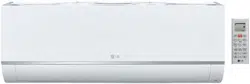
Multi F and Multi F MAX Standard
Wall-Mounted Units
This manual describes how to install the LG Multi F and Multi F MAX
(Multi Zone) Standard Wall-Mounted Indoor Units (IDU) for Multi
F heat pump systems. Table 1 lists the available models. Refer to
LG’s Multi F Indoor Unit Engineering Manual for complete detailed
engineering data and selection procedures.
Safety
Safety of personnel is the primary concern during all
procedures. Read and understand the safety summa-
ry at the front of this manual. Read and understand
this installation procedure before beginning instal-
lation. Use the appropriate tools and accessories
during installation. Plan your work and do not work
alone, if possible. Know how to obtain emergency
medical and fire fighting assistance.
Installation Personnel
This equipment is intended for installation by personnel trained
in the required construction, mechanical, electrical, and/or other
disciplines.
Applicable Codes
Personnel must be familiar with and follow the applicable national,
state, and/or local codes. In the event of a conflict between any
applicable code and the instructions in this manual, comply with the
applicable code.
• Connecting cable (power and control)
• Pipes - vapor line and liquid line, with
insulation
• 3/8” or 1/2” Threaded hanger rods
• 3/8” or 1/2” nuts, at washers, and
lock/split washers
• Insulated drain hose
• Additional drain hose
• Level
• Screwdriver
• Electrical lineman pliers
• Electric drill
• Hole saw
• Drill
• Flaring tool set
• Tubing cutter
• Tube/pipe reamer
• Torque wrenches
• Allen wrench
• Gas-leak detector
• Thermometer
WARNING
Installation work must be performed by trained personnel and in
accordance with national wiring standards and all local or other
applicable codes. Improper installation can result in re, electric shock,
physical injury, or death.
Note:
Please read all instructions before installing this product. Become familiar
with the unit’s components and connections, and the order of installation.
Incorrect installation can degrade or prevent proper operation.
Figure 1: Typical Multi F Standard Wall-Mounted Indoor Unit
Required Tools (field provided)
Required Parts (field provided)
10
Multi F Standard Wall-Mounted Indoor Unit
Due to our policy of continuous product innovation, some specifications may change without notification.
©LG Electronics U.S.A., Inc., Englewood Cliffs, NJ. All rights reserved. “LG” is a registered trademark of LG Corp.
MA
X
MUL
TI
F
MUL
TI
F
Typical Unit Model Number
Nominal Capacity
Cooling (Btu) Heating (Btu)
LMN077HVT 7,000 8,100
LSN090HSV4 9,000 10,400
LSN120HSV4 12,000 13,800
LMN157HVT 14,300 16,500
LSN180HSV4 18,000 20,800
LMN247HVT 24,000 27,000
Table 1: Multi F Standard Wall-Mounted Indoor Units
INTRODUCTION
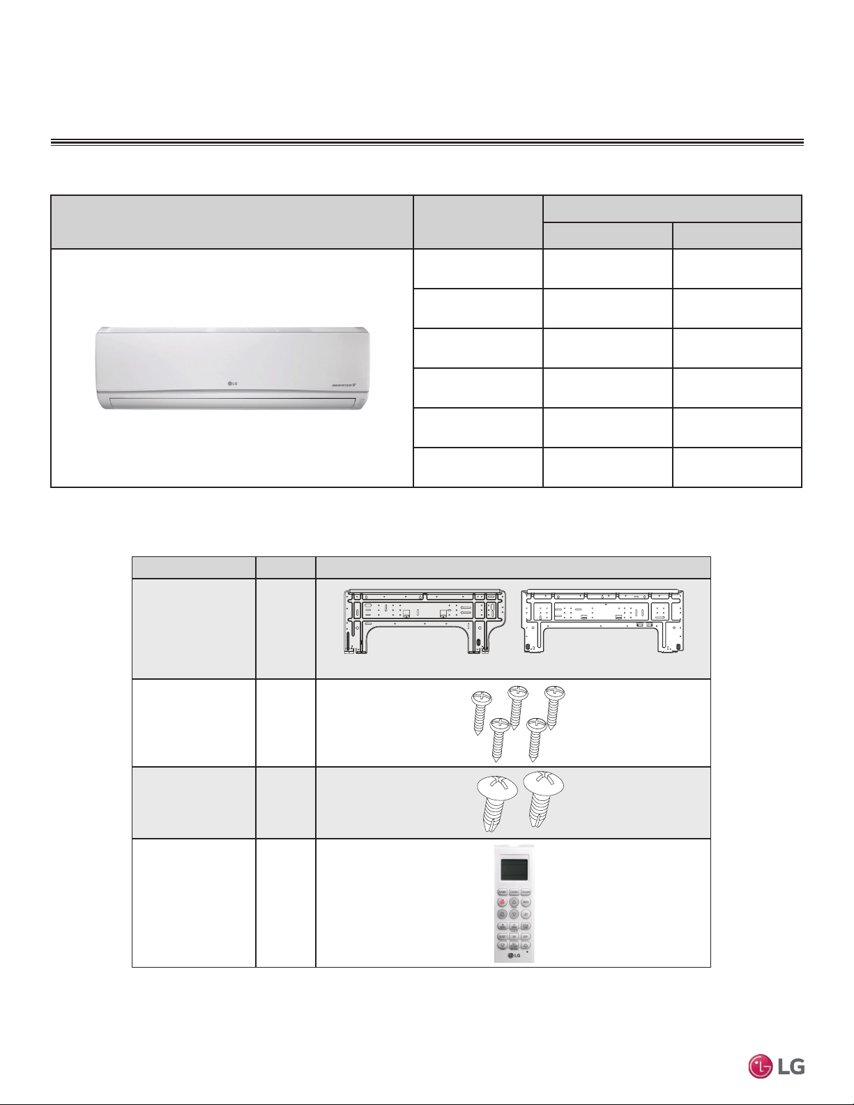
Part Quantity Image
Installation Plate One (1)
Type “A” Screws Five (5)
Type “B” Screws
(M4 x 12L)
Two (2)
Wireless
Controller with Holder
HVT: AKB73635606
HSV: AKB73835312
One (1)
7,000 ~ 15,000 Btu/h Indoor Units
18,000 and 24,000 Btu/h Indoor Units
Table 2: Included Items
11
Installation Manual
Due to our policy of continuous product innovation, some specifications may change without notification.
©LG Electronics U.S.A., Inc., Englewood Cliffs, NJ. All rights reserved. “LG” is a registered trademark of LG Corp.
MA
X
MUL
TI
F
MUL
TI
F
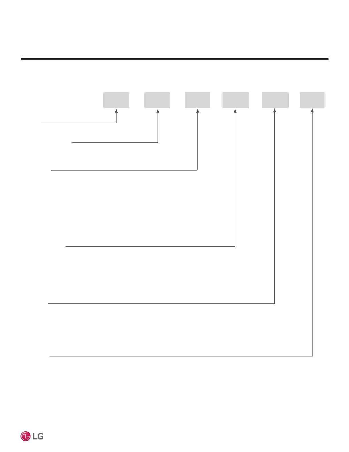
UNIT NOMENCLATURE
Multi F Multi-Zone Systems — Indoor Units
M
N 157 HVT
Generation
3 = Third (also Third Gen if no number in this position)
4 = Fourth
Features:
H = Heat Pump
V = Inverter
T = High Wall-Mounted Indoor Unit
P = Art Cool Gallery Indoor Unit
Nominal Capacity
(Nominal cooling capacity in Btu/h):
Component:
AN: Art Cool™ Wall-Mounted Indoor Unit
N: Standard Wall-Mounted Indoor Unit
CN: Four-Way Ceiling-Cassette Indoor Unit
DN: Ceiling-Concealed Duct (Low Static) Indoor Unit
HN: Ceiling-Concealed Duct (High Static) Indoor Unit
VN: Vertical-Horizontal Air Handling Indoor Unit
L = LG
077 = 7,000
090 = 9,000
120 = 12,000
157 = 15,000
180 = 18,000
247 = 24,000
L
• Voltage for all equipment is 208-230V, 60 Hz, 1-phase.
• All indoor units are compatible with wired controllers
Type: M = Multi-Zone
S = Single Zone (Gen 4 Single Zone units also compatible with Multi Zone)
12
Multi F Standard Wall-Mounted Indoor Unit
Due to our policy of continuous product innovation, some specifications may change without notification.
©LG Electronics U.S.A., Inc., Englewood Cliffs, NJ. All rights reserved. “LG” is a registered trademark of LG Corp.
MA
X
MUL
TI
F
MUL
TI
F
GENERAL DATA
R410A Refrigerant
R410A refrigerant has a higher operating pressure in comparison to R22 refrigerant and, therefore, all piping system materials
installed must have a higher resisting pressure than the materials traditionally used in R22 systems.
R410A refrigerant is an azeotrope of R32 and R125, mixed at 50:50, so the ozone depletion potential (ODP) is 0.
WARNING
• Do not place refrigerant cylinder in direct sunlight. Refrigerant cylinder may explode causing severe injury or death.
Note
• Because R410A is a combination of R32 and R125, the required additional refrigerant must be charged in its liquid state. If the
refrigerant is charged in its gaseous state, its composition changes and the system will not work properly.
• Do not heat piping more than necessary during installation. Piping may become soft and fail when pressurized.
• Do not use any piping that has not been approved for use in high-pressure refrigerant systems. Piping wall thickness must comply
with the applicable local, state, and federal codes for the 551 psi design pressure of R410A. Inadequate piping may fail when
pressurized.
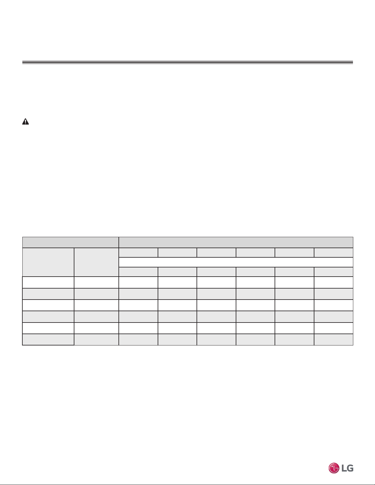
Indoor units Outdoor units
Model Number
Indoor Unit Nominal
Capacity (Btu/h)
LMU18CHV LMU24CHV LMU30CHV LMU36CHV LMU480HV LMU540HV
Maximum No. of Connectable Indoor Units
2 3 4 4 8 8
LMN077HVT 7,000 O O O O O O
LSN090HSV4 9,000 O O O O O O
LSN120HSV4 12,000 O O O O O O
LMN157HVT 15,000 O O O O O O
LSN180HSV4 18,000 – O O O O O
LMN247HVT 24,000 – O O O O O
Table 3: Allowable Indoor Unit to Outdoor Unit Connections.
Allowable Indoor Unit to Outdoor Unit Connections
In Multi F/Multi Zone systems, the standard wall-mounted IDUs can be connected to the Multi F outdoor units (ODUs) listed in Table 3.
connection allowed: O
connection not allowed: –
Device Connection Limitations
• The minimum number of connected and operating indoor units to Multi F / Multi F MAX systems is two.
• The maximum number of indoor units for each Multi F / Multi F MAX heat pump system is:
LMU18CHV = 2 LMU24CHV = 3 LMU30CHV = 4
LMU36CHV = 4 LMU480HV = 8 LMU540HV = 8
• The maximum allowable total indoor unit capacity (Btu/h) for each Multi F / Multi F MAX heat pump system is:
LMU18CHV = 24,000 LMU24CHV = 33,000 LMU30CHV = 40,000
LMU36CHV = 48,000 LMU480HV = 65,000 LMU540HV = 73,000
• Refer to the Multi F Engineering Manual to properly determine total indoor unit connected capacity.
13
Installation Manual
Due to our policy of continuous product innovation, some specifications may change without notification.
©LG Electronics U.S.A., Inc., Englewood Cliffs, NJ. All rights reserved. “LG” is a registered trademark of LG Corp.
MA
X
MUL
TI
F
MUL
TI
F
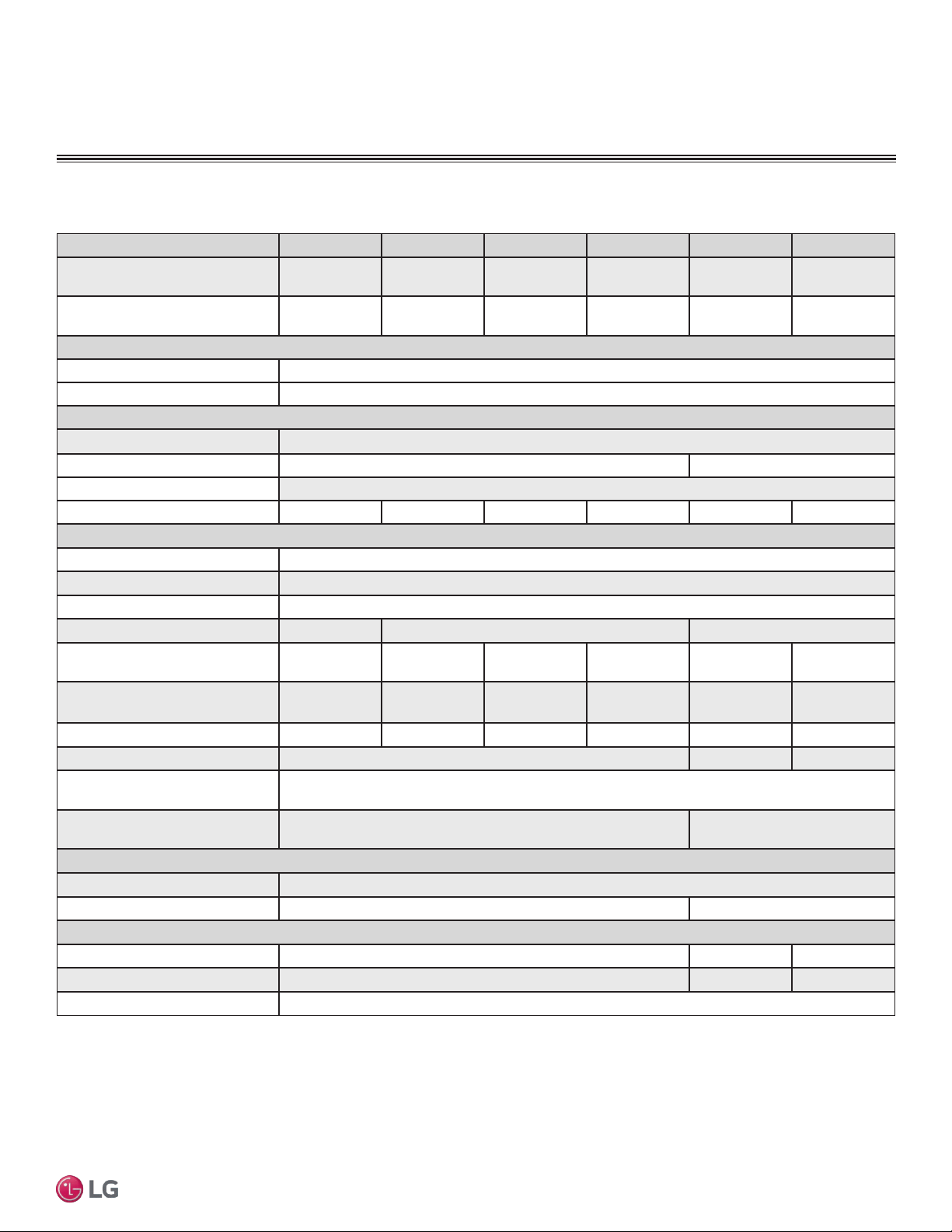
Table 4: Multi F Multi Zone Standard Wall-Mounted Indoor Unit Specications
GENERAL DATA
Specications
Model Name LMN077HVT LSN090HSV4 LSN120HSV4 LMN157HVT LSN180HSV4 LMN247HVT
Nominal Cooling Capacity
(Btu/h)
1
7,000 9,000 12,000 14,300 18,000 24,000
Nominal Heating Capacity
(Btu/h)
1
8,100 10,400 13,800 16,500 20,800 27,000
Operating Range
Cooling (°F WB)
57-77
Heating (°F DB)
59-81
Fan
Type
Cross Flow
Motor Output (W) x Qty.
14.4 x 1 76.0 x 1
Motor/Drive
Brushless Digitally Controlled / Direct
Airflow Rate CFM (H/M/L)
198 / 177 / 162 247 / 230 / 212 335 / 318 / 300 371 / 318 / 247 572 / 501 / 434 720 / 600 / 466
Unit Data
Refrigerant Type
2
R410A
Refrigerant Control
Electronic Expansion Valve (EEV)
Power Supply V, Ø, Hz
3
208-230, 1, 60
Rated Amps (A)
0.1 0.2 0.3
Sound Pressure Level ±3 dB(A)
(H/M/L)
4
33 / 30 / 26 33 / 30 / 27 39 / 36 / 31 43 / 39 / 34 37 / 33 / 28 42 / 39 / 36
Dimensions (W x H x D, in.)
35-1/4 x 11-3/8
x 8-9/32
34-7/8 x 11-1/4
x 8-1/4
34-7/8 x 11-1/4
x 8-1/4
35-1/4 x 11-3/8
x 8-9/32
40-9/16 x 12-13/16
x 9-13/16
40-9/16 x 12-25/32
x 9-27/32
Net Unit Weight (lbs.)
23 20 20 23 31 32
Shipping Weight (lbs.)
26 36 37
Power Wiring / Communications
Cable (No. x AWG)
5
4 x 18
Heat Exchanger (Row x Column
x Fin / inch) x Number
(2 x 16 x 23) x 1 (3 x 18 x 22) x 1
Pipe Size
Liquid (in.)
1/4
Vapor (in.)
3/8 1/2
Connection Size
Liquid (in.)
1/4 3/8 1/4
Vapor (in.)
3/8 5/8 1/2
Drain O.D. / I.D. (in.)
27/32, 5/8
1
Nominal capacity is rated 0 ft. above sea level with corresponding refrigerant piping
length in accordance with standard length of each outdoor unit and a 0 ft. level difference
between outdoor and indoor units. All capacities are net with a combination ratio between
95 – 105%.
Nominal cooling capacity rating obtained with air entering the indoor unit at 80ºF dry bulb
(DB) and 67ºF wet bulb (WB) and outdoor ambient conditions of 95ºF dry bulb (DB) and
75ºF wet bulb (WB).
Nominal heating capacity rating obtained with air entering the indoor unit at 70ºF dry bulb
(DB) and 60ºF wet bulb (WB) and outdoor ambient conditions of 47ºF dry bulb (DB) and
43ºF wet bulb (WB).
2
This unit comes with a dry helium charge.
3
Acceptable operating voltage: 187V-253V.
4
Sound pressure levels are tested in an anechoic chamber under ISO Standard 3745 and
are the same in both cooling and heating mode. These values can increase due to ambient
conditions during operation.
5
All power wiring / communications cable to be minimum 18 AWG, 4-conductor, stranded,
shielded, and must comply with applicable local and national codes.
14
Multi F Standard Wall-Mounted Indoor Unit
Due to our policy of continuous product innovation, some specifications may change without notification.
©LG Electronics U.S.A., Inc., Englewood Cliffs, NJ. All rights reserved. “LG” is a registered trademark of LG Corp.
MA
X
MUL
TI
F
MUL
TI
F
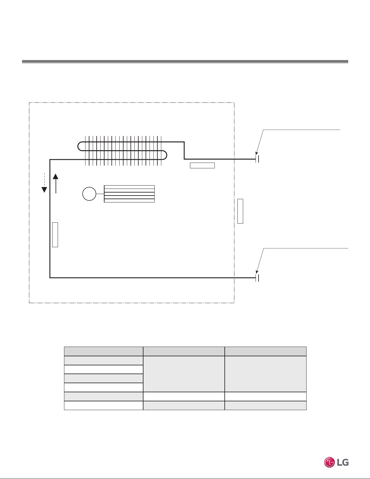
GENERAL DATA
Gas pipe connection port
(flare connection)
Liquid pipe connection port
(flare connection)
Cooling
Heating
Thermistor for
Evaporator Inlet Temperature
Thermistor for
Indoor Air Temperature
Thermistor for Evaporator
Outlet Temperature
Heat Exchanger
Cross Flow Fan
M
Model No. Vapor (inch) Liquid (inch)
LMN077HVT
Ø3/8 Ø1/4
LSN090HSV4
LSN120HSV4
LMN157HVT
LSN180HSV4 Ø5/8 Ø3/8
LMN247HVT Ø1/2 Ø1/4
Table 5: Multi F Multi Zone Standard Wall-Mounted Indoor Unit Refrigerant Pipe Connection Port Diameters
15
Installation Manual
Due to our policy of continuous product innovation, some specifications may change without notification.
©LG Electronics U.S.A., Inc., Englewood Cliffs, NJ. All rights reserved. “LG” is a registered trademark of LG Corp.
MA
X
MUL
TI
F
MUL
TI
F
GENERAL DATA
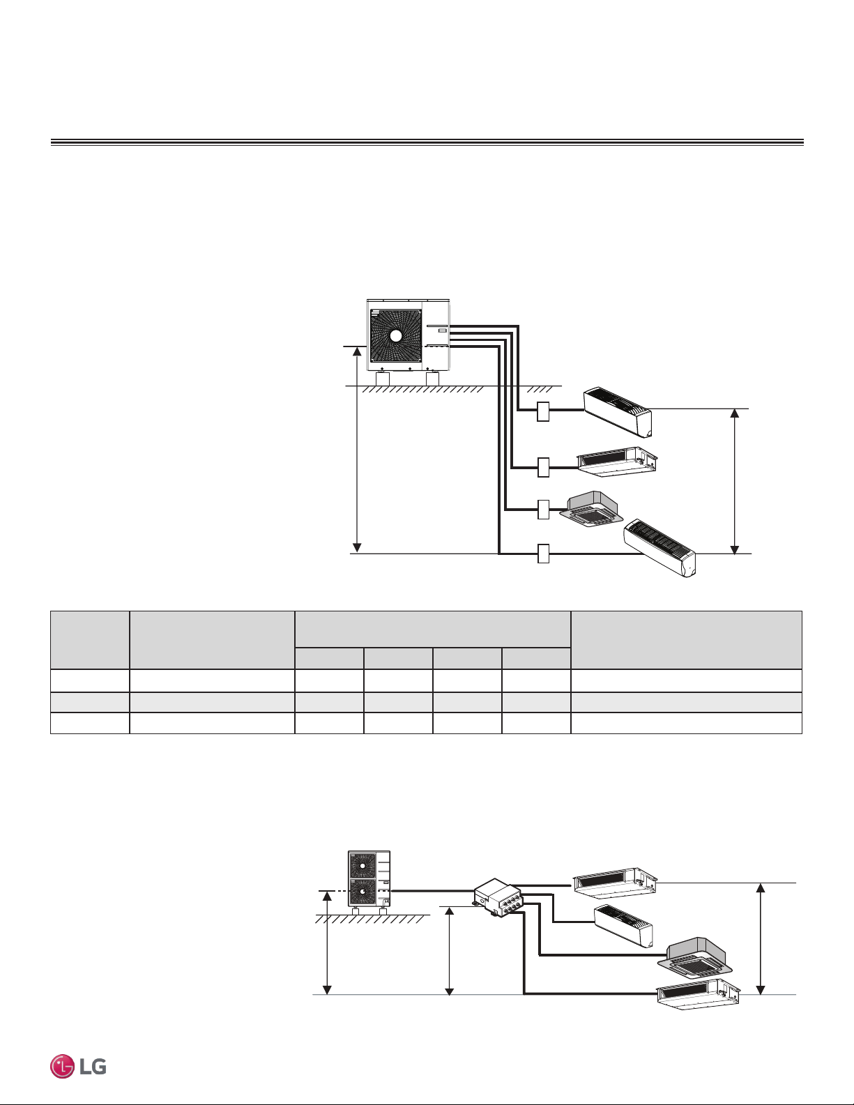
Typical Multi F/Multi F Max Systems
Max. 49.2 feet
Max. 24.6 feet
A
B
C
D
Typical Multi F System
Example: LMU36CHV outdoor unit with four (4)
indoor units connected.
ODU: Outdoor Unit.
IDU: Indoor Unit.
A, B, C, D: Piping from Outdoor Unit to Indoor Unit.
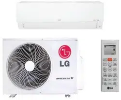
Major System Components
A typical Multi F system consists of an outdoor unit (ODU), refrigerant piping, and two to four indoor units (IDUs). The standard
wall-mounted units described in this manual are one of the types of IDUs that can be connected to a Multi F system.
A typical Multi F Max system consists of an ODU, refrigerant piping, one or two branch distribution units (BDU), and two to eight
IDUs. The standard wall-mounted units described in this manual are one of the types of IDUs that can be connected to a Multi F
Max system.
Example: LMU540HV outdoor unit with four
(4) indoor units, and one (1) branch distribu-
tion unit connected.
ODU: Outdoor Unit.
IDU: Indoor Unit.
BDU: Branch Distribution Unit.
A: Main Piping.
B: Branch Piping (Branch Distribution Unit to
Indoor Unit[s]).
A
h2 ≤ 49.2 feet
h3 ≤ 32.8 feet
h1 ≤ 98.4 feet
BDU
ODU
IDU
IDU
IDU
IDU
B
B
B
B
Typical Multi F MAX System with One Branch Distribution Unit
Outdoor
Unit
Minimum Length for Each
Pipe Segment (ft.)
Maximum Equivalent Pipe Length
to Each Indoor Unit (ft.)
Maximum Equivalent Pipe Length
for Each System (ft.)
A B C D
LMU18CHV 10 82 82 - - 164
LMU24CHV 10 82 82 82 - 246.1
LMU36CHV 10 82 82 82 82 246.1
Table 6: Multi F Outdoor Unit Refrigerant Piping System Limitations.
16
Multi F Standard Wall-Mounted Indoor Unit
Due to our policy of continuous product innovation, some specifications may change without notification.
©LG Electronics U.S.A., Inc., Englewood Cliffs, NJ. All rights reserved. “LG” is a registered trademark of LG Corp.
MA
X
MUL
TI
F
MUL
TI
F
GENERAL DATA
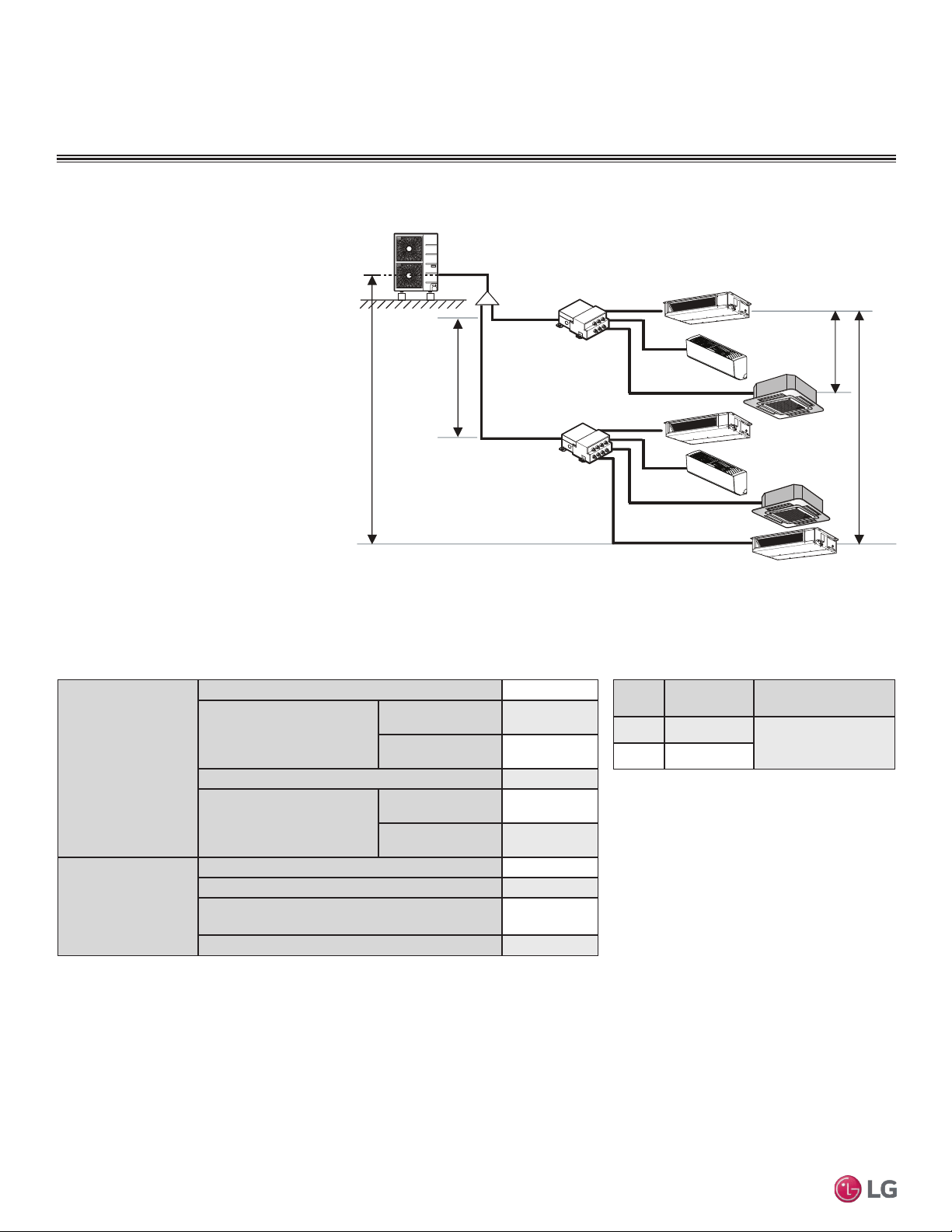
Typical Multi F/Multi F Max Systems
Example: LMU540HV outdoor unit with seven
(7) indoor units, and two (2) branch distribu-
tion units connected.
ODU: Outdoor Unit.
IDU: Indoor Unit.
BD: Branch Distribution Unit(s).
ΣA: Main Piping.
ΣB: Branch Piping (Branch Distribution Unit[s]
to Indoor Unit[s]).
B
A
h2 ≤ 49.2 feet
A
h3 ≤ 32.8 feet
h4 ≤ 49.2 feet
h1 ≤ 98.4 feet
BDU Y-Branch
BDU
IDU
A
ODU
IDU
IDU
IDU
IDU
IDU
IDU
B
B
B
B
B
B
Typical Multi F MAX System with Two Branch Distribution Units
Table 7: Multi F MAX Outdoor Unit Refrigerant Piping System Limitations.
Pipe Length
(ELF = Equivalent
Length of pipe
in Feet)
Total piping length (ΣA + ΣB)
≤475.7 feet
Main pipe
(Outdoor Unit to Branch
Distribution Units: ΣA)
Minimum
10 feet
Maximum
≤180.4 feet
Total branch piping length (ΣB)
≤295.3 feet
Branch pipe
(Branch Distribution Units
to Indoor Units: B)
Minimum
10 feet
Maximum
≤49.2 feet
Elevation Differential
(All Elevation
Limitations are
Measured in
Actual Feet)
If outdoor unit is above or below indoor unit (h1)
≤98.4 feet
Between the farthest two indoor units (h2)
≤42.9 feet
Between branch distribution unit and farthest
connected indoor unit(s) (h3)
≤32.8 feet
Between branch distribution units (h4)
≤42.9 feet
Table 8: Multi F MAX Piping Sizes.
Piping
Main Pipe A
(inch)
Branch Pipe B
Liquid Ø3/8
Depends on the size
of the indoor unit piping
Gas Ø3/4
17
Installation Manual
Due to our policy of continuous product innovation, some specifications may change without notification.
©LG Electronics U.S.A., Inc., Englewood Cliffs, NJ. All rights reserved. “LG” is a registered trademark of LG Corp.
MA
X
MUL
TI
F
MUL
TI
F
Table 9: Equivalent Piping Length for Elbows,
Y-branches, and Branch Distribution Units.
1
Kit contains two Y-branches: one for liquid and one for vapor.
Component
Size (Inches)
1/4 3/8 1/2 5/8 3/4
Elbow (ft.)
0.5 0.6 0.7 0.8 1.2
Y-Branch Kit (ft.)
(Multi F MAX systems only)
1
1.6
Branch Distribution Unit (ft.)
(Multi F MAX systems only)
8.2
Field-supplied elbows are allowed if they are long radius and designed for use with R410A refrigerant. Be
sure to account for the additional pressure losses in equivalent pipe length calculations for each elbow,
y-branch, and branch distribution unit. The equivalent pipe length of each elbow, Y-branch, and/or branch
distribution unit must be added to each pipe segment to ensure maximum lengths are not exceeded.
Using Refrigerant Components
Field Supplied Refrigerant Piping
Type ACR copper is the only approved refrigerant pipe material for use with LG Multi F air conditioning
products. ACR rated tubing is the only type that ships with yellow caps. Approved tubing for use with
Multi V products will be marked “R410 RATED” along the length of the tube. Tube wall thickness should
meet local code requirements and be approved for a maximum operating pressure of 551 psi.
Refer to the refrigerant piping section (starting on page 22) of the General Installation Guidelines for
more information on piping.
GENERAL DATA
Refrigerant Piping Requirements
18
Multi F Standard Wall-Mounted Indoor Unit
Due to our policy of continuous product innovation, some specifications may change without notification.
©LG Electronics U.S.A., Inc., Englewood Cliffs, NJ. All rights reserved. “LG” is a registered trademark of LG Corp.
MA
X
MUL
TI
F
MUL
TI
F
DANGER
To avoid the possibility of re, do not install the unit in an area where combustible gas may generate, ow, stagnate, or leak. Failure to do so will
cause serious bodily injury or death. Before beginning installation, read the safety summary at the beginning of this manual.
Select a location for installing the wall-mounted indoor unit (IDU) that meets the following conditions:
• Where there is enough structural strength to bear the weight of the unit
• Where air circulation will not be blocked
• Where noise prevention is taken into consideration
• Ensure there is sufcient space from the ceiling and oor
• Locate the indoor unit in a location where it can be easily connected to the outdoor unit/branch distribution unit
• Include space for drainage to ensure condensate ows properly out of the unit when it is in cooling mode
• Use a level indicator to ensure the unit is installed on a level plane
Note:
The unit may be damaged, may malfunction, and/or will not operate as designed if installed in any of the following conditions:
Do not install the unit where it will be subjected to direct thermal radiation from other heat sources.
Do not install the unit in an area where combustible gas may generate, flow, stagnate, or leak.
Do not install the unit in a location where acidic solution and spray (sulfur) are often used.
Do not use the unit in environments where oil, steam, or sulfuric gas are present.
Do not install additional ventilation products on the chassis of the unit.
Do not install the unit near high-frequency generator sources.
Do not install the unit near a doorway.
Installing in an Area Exposed to Unconditioned Air
In some installation applications, areas (floors, walls) in some rooms may be exposed to unconditioned air (room may be above or next to an
unheated garage or storeroom). To countermeasure:
• Verify that carpet is or will be installed (carpet may increase the temperature by three degrees).
• Add insulation between the oor joists.
• Install radiant heat or another type of heating system to the oor.
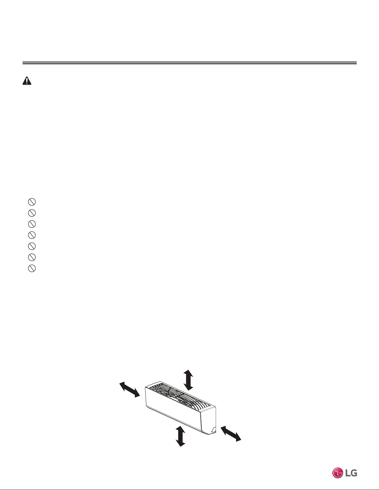
Required Clearances
Figure 6 shows required clearance distances around a typical installed wall-mounted unit.
GENERAL INSTALLATION GUIDELINES
>4 inches
Recommended height
>6-1/2 feet from floor
>4 inches
HVT; 9/12k HSV4 Units: ≥5 inches
LSN180HSV4 Units: ≥8 inches
Location Selection
Figure 2: Required Clearances Around Typical Installed Unit
19
Installation Manual
Due to our policy of continuous product innovation, some specifications may change without notification.
©LG Electronics U.S.A., Inc., Englewood Cliffs, NJ. All rights reserved. “LG” is a registered trademark of LG Corp.
MA
X
MUL
TI
F
MUL
TI
F
GENERAL INSTALLATION GUIDELINES
Unpack and Inspect for Freight Damage
CAUTION
Shipping and net weights of the wall-mounted units are listed in Table 4. To help avoid injury to personnel and
damage to the unit, use two people when carrying a unit by hand.
Note:
Do not unpack the unit and remove the protective materials until ready to install. Before unpacking,
carefully move the packaged unit to a work area near the installation location.
After opening, if the unit is damaged, repack the unit as it was shipped to you. RETAIN ALL PACKING
MATERIALS. In general, freight damage claims will be denied if the original packing materials are not
retained for the claims adjustor to inspect. Contact your supervisor on how to proceed with filing a freight
claim and to order a replacement unit.
Note:
Before opening the shipping container, check the container labeling to verify the unit received is the correct
unit. Verify the unit capacity, type, and voltage. Refer to the chart on “Dimensions of the Flare” on page 29.
1. Before opening the shipping container, verify you have the correct unit as described in the Note
above.
2. Place the box on a solid surface right side up.
3. Cut the white reinforced nylon straps.
4. Open the top of the box and fold back all four flaps.
5. Remove the protective cardboard/Styrofoam® top sheet and place to the side.
6. The walls and top panels are not attached to the bottom of the box. Lift the cardboard carton by the
flaps and remove the box walls and top and place it to the side.
7. Remove the moisture barrier plastic bonnet.
8. Check the unit nameplate data and model number. Verify the unit voltage, and capacities are correct
before proceeding.
9. Locate and retain the piping/condensate accessory kit located in the bottom of the box under the
refrigerant pipe stubs.
10. Using two people, carefully lift the unit and inspect for freight damage. DO NOT lift by the refrigerant
piping or drain pipe stub. Lift by the hangar brackets or chassis frame only. If damage is found, repack
the unit as it was received in the original container.
11. If the unit is undamaged, remove and retain the installation manual. It is located under or on top of
the unit.
Inspection
20
Multi F Standard Wall-Mounted Indoor Unit
Due to our policy of continuous product innovation, some specifications may change without notification.
©LG Electronics U.S.A., Inc., Englewood Cliffs, NJ. All rights reserved. “LG” is a registered trademark of LG Corp.
MA
X
MUL
TI
F
MUL
TI
F
GENERAL INSTALLATION GUIDELINES
WARNING
• Mounting hardware must be securely installed to prevent the chas-
sis falling from its installation location. There is risk of personnel
injury or property damage from falling equipment.
• When choosing a location for the wall mount plate, be sure to take
into consideration routing of wiring for power outlets within the wall.
Touching wiring can cause serious bodily injury, or death.
• Installation work must be performed by trained personnel and in
accordance with all local or other applicable codes. There is risk of
injury to personnel from incorrect installation.
Note:
• Ensure the unit is properly installed. Incorrectly installed units can
result in degraded performance or an inoperative unit/system.
• Use a level indicator to ensure the installation plate and chassis
are installed on a level plane.
• If the unit is installed near a body of water, certain components
are at risk of being corroded. Appropriate anti-corrosion methods
should be taken for the unit and all components.
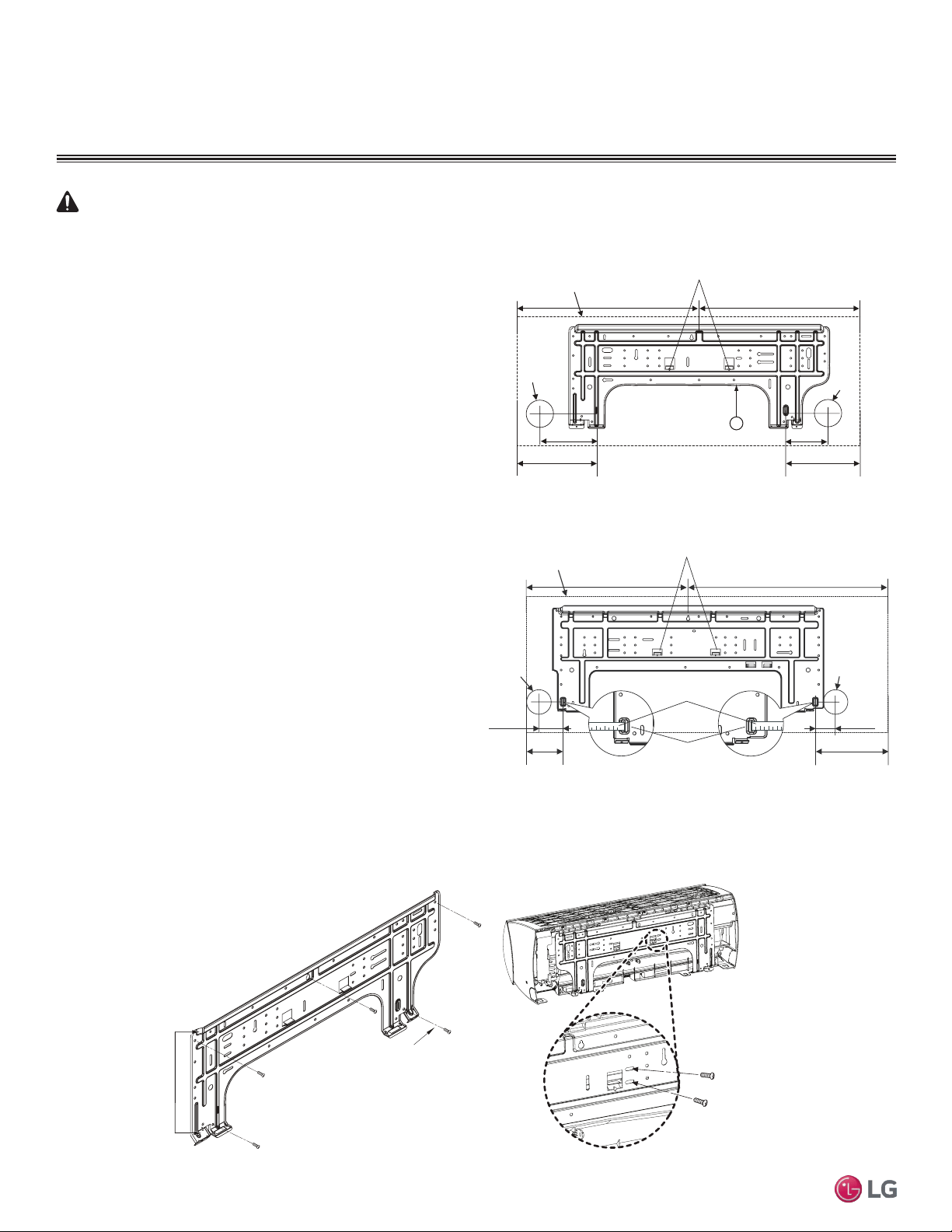
Install Wall-Mounted IDU Chassis
Mounting the Installation Plate
The mounting wall should be strong and solid enough to protect the
unit from vibration. It should securely hold the installation plate and
the weight of the chassis.
1. Determine the installation location.
2. Refer to Figure 3 or Figure 4 for the appropriate mounting
diagram.
3. Mount the installation plate on the wall using the Type “A” screws.
If mounting the unit on concrete, consider using anchor bolts.
Use a level to ensure the plate is level.
4. Always mount the installation plate horizontally. Measure the wall
and mark the centerline using thread and a level.
Figure 3: Installation Plate for LMN077HVT, LSN090HSV4,
LSN120HSV4, and LMN157HVT Units.
Installation Plate
Frame
Hooks
Type "A" Screws
Figure 4: Installation Plate for LSN180HSV4 and LMN247HVT Units.
Figure 5: Installation Plate Attaching Screw Placement.
Ø2-3/4 inches
Ø2-3/4 inches
2-23/32 inches
2-7/32 inches
Right rear
piping
Left rear
piping
Installation Plate
Measuring Tape
Measuring Tape Hanger
Place a level on raised tab
Unit Outline
8-5/32 inches
4-1/8 inches
18-1/8 inches 22-7/16 inches
Ø2-9/16
5-3/16 3-11/16
Right rear piping
Left rear piping
Place a level on raised tab
Unit Outline
8-1/2
6-7/8
17-3/8 17-3/8
5
Ø2-9/16
A-Type
B-Type
21
Installation Manual
Due to our policy of continuous product innovation, some specifications may change without notification.
©LG Electronics U.S.A., Inc., Englewood Cliffs, NJ. All rights reserved. “LG” is a registered trademark of LG Corp.
MA
X
MUL
TI
F
MUL
TI
F
GENERAL INSTALLATION GUIDELINES
Install Wall-Mounted IDU Chassis
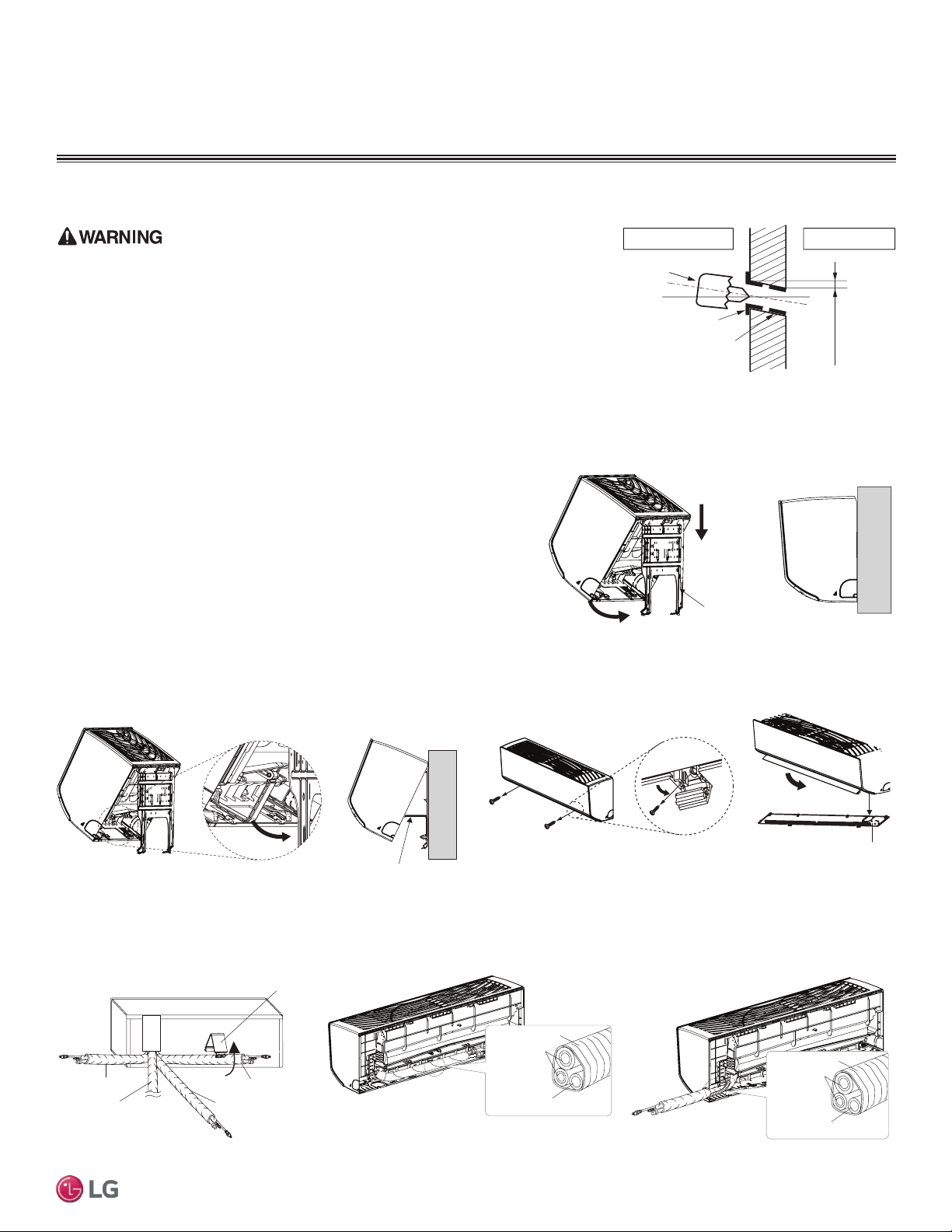
Drilling Piping Hole in the Wall
Use caution when drilling holes through walls. Drilling into power wiring in the wall can
cause serious bodily injury or death.
Follow the left or right piping clearance recommendations in Figure 3 or Figure 4.
1. Using a 2-5/8 (ø 65mm) inch hole core drill bit, drill a hole at either the right or
left side of the wall mounting (Figure 6). The hole should slant 3/16” to 5/16” from
level (upward on the indoor unit side and downward on the outdoor unit side).
2. Finish off the newly drilled hole as shown with bushing and sleeve covering.
Sleeve and bushing prevents damage to the tubing/bundling of the piping.
(3/16"~5/16")
Indoor
WALL
Outdoor
Bushing
Core Drill
Sleeve
Figure 6: Drilling Piping Hole
Hanging the Indoor Unit Chassis
1. Attach the three (3) hooks on the top of the indoor unit to the top edge of
the installation plate. Verify the hooks are properly attached to the instal-
lation plate by gently shaking the indoor unit from side to side.
2. Unlock the tubing clamp from the indoor unit frame. For easier access be-
tween the bottom of the indoor unit and the wall, prop the clamp between
the indoor unit frame and installation plate.
3. Remove the screw covers at the bottom of the indoor unit, unscrew the
two (2) screws, remove the frame cover, remove the piping connection
cover, and position the piping for installation (down, back, left, or right).
Installation plate
Figure 7: Locking the Indoor Unit onto the Installation Plate.
Tubing Clamp
Figure 8: Accessing the Back of the Indoor Unit.
Right
Tubing Clamp
Down
Left
Back
Frame Cover
Figure 9: Removing the Frame Cover.
Figure 10: Exterior Back View of Indoor Unit. Figure 11: Piping Installed to the Left.
Figure 12: Piping Installed to the Right.
Connecting
pipe
Tape
Drain hose
Connecting
pipe
Tape
Drain hose
22
Multi F Standard Wall-Mounted Indoor Unit
Due to our policy of continuous product innovation, some specifications may change without notification.
©LG Electronics U.S.A., Inc., Englewood Cliffs, NJ. All rights reserved. “LG” is a registered trademark of LG Corp.
MA
X
MUL
TI
F
MUL
TI
F
Preparing for Piping Installation to the Indoor Unit
Note:
Do not bend the piping / drain hose from side to side, it may damage the components.
Prepare the refrigerant piping and drain hose (indoor unit piping) for installation through the wall. Press on the top of the tubing clamp
and slowly guide the piping/hose down (depending on installation requirements, then to the left or right). Relock the tubing clamp after
the piping/hose are released.
GENERAL INSTALLATION GUIDELINES
Refrigerant Piping
Field-Provided Isolation Ball Valves
LG recommends installing field-supplied ball valves with Schrader ports at each indoor unit. Full-port isolation ball valves with Schrader
ports (positioned between valve and indoor unit) rated for use with R410A refrigerant should be used on both the liquid and vapor lines.
For Multi F MAX systems, position valves with a minimum distance of three (3) to six (6) inches of pipe on either side of the valve, and
between six (6) and twelve (12) inches from the first upstream Y-branch or branch distribution unit. If ball valves are installed away from
the first Y-branch and/or branch distribution unit and closer to the indoor unit, oil may accumulate where it cannot be returned to the
outdoor unit and may cause a shortage of oil in the compressor.
Valves should be easily accessible for service. If necessary, install drywall access doors or removable ceiling panels, and position the
valves to face the access door or ceiling panel opening. Mount valves with adequate space between them to allow for placement of
adequate pipe insulation around the valves.
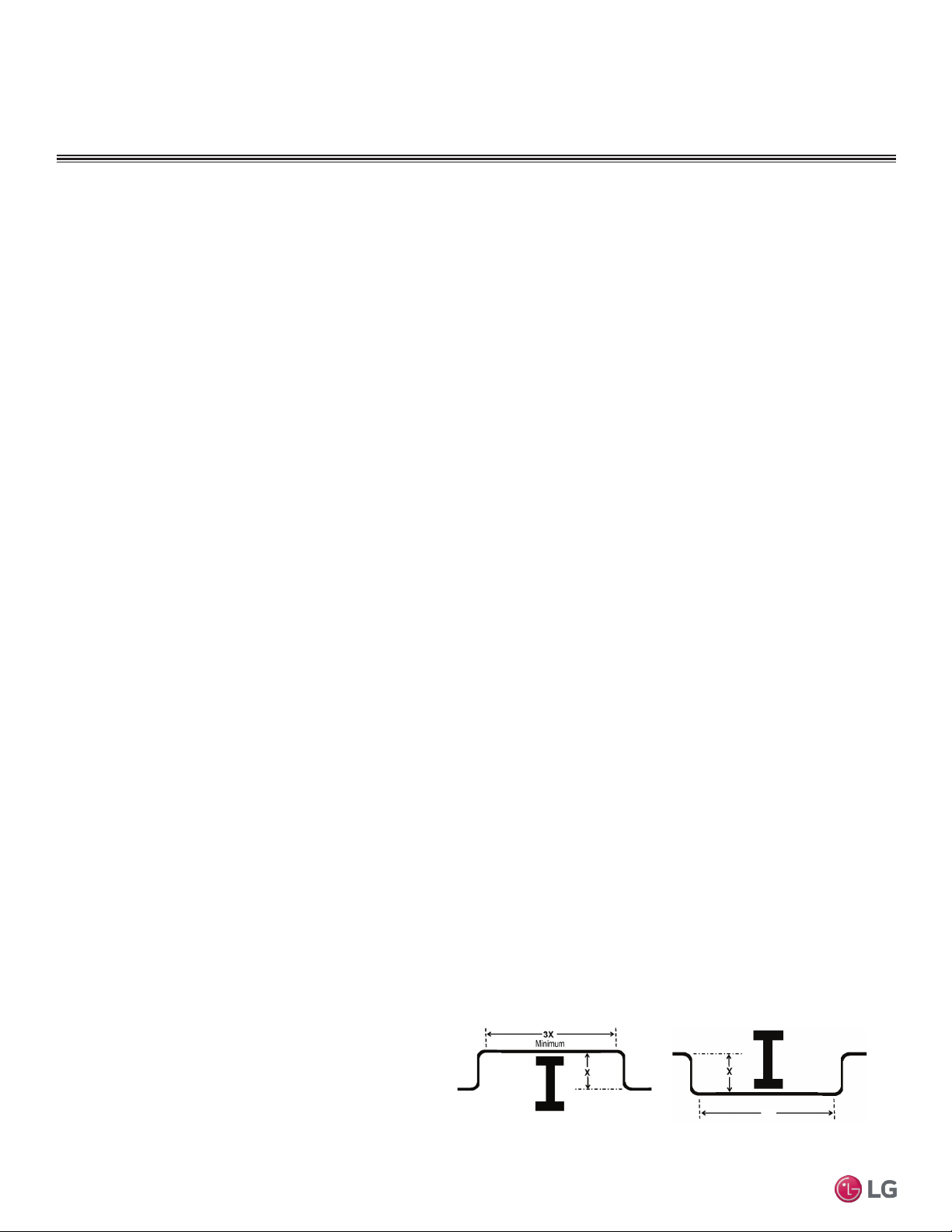
Figure 13: Installing Piping Above and Below an Obstacle.
Above an obstacle.
3X
Minimum
Below an obstacle.
Obstacles
When an obstacle, such as an I-beam or concrete T, is in the
path of the planned refrigerant pipe run, it is best practice to
route the pipe over the obstacle. If adequate space is not avail-
able to route the insulated pipe over the obstacle, then route
the pipe under the obstacle. In either case, it is imperative the
horizontal section of pipe above or below the obstacle be a
minimum of three (3) times greater than the longest vertical rise
(or fall) distance.
Pipe Slope
The horizontal pipe slope cannot exceed 10° up or down.
In-line Refrigeration Components
Components such as oil traps, solenoid valves, filter-dryers, sight glasses, tee fittings, and other after-market accessories are not per-
mitted on the refrigerant piping system between the outdoor units and the indoor / branch distribution units.
Multi F/Multi F Max systems have redundant systems that ensure oil is properly returned to the compressor. Sight-glasses and solenoid
valves may cause vapor to form in the liquid stream.
Note:
Over time, dryers may deteriorate and introduce debris into the system. The designer and installer should verify the refrigerant piping system is
free of traps, sagging pipes, sight glasses, lter dryers, etc.
No Pipe Size Substitutions
Use only the pipe size selected by the LATS Multi F pipe system design software or as conveyed in the product installation instructions.
Using a different size is prohibited and may result in a system malfunction or failure to work at all.
23
Installation Manual
Due to our policy of continuous product innovation, some specifications may change without notification.
©LG Electronics U.S.A., Inc., Englewood Cliffs, NJ. All rights reserved. “LG” is a registered trademark of LG Corp.
MA
X
MUL
TI
F
MUL
TI
F
Refrigerant Piping
GENERAL INSTALLATION GUIDELINES
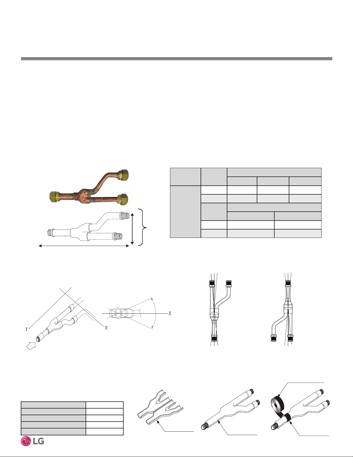
The LG supplied Y-Branch Kit PMBL5620 MUST be used when two branch distribution units are connected to one Multi F MAX system.
Field-supplied fittings are not permitted. Each Y-Branch kit comes with two (2) Y-branches (one for the liquid line and one for the vapor line)
and insulation covers.
Y-branches may be installed in horizontal or vertical configurations. When installed vertically, position the Y-branch so the straight-through
leg is ±3° of plumb. When installed horizontally, position the Y-branch so the take-off leg is level and shares the same horizontal plane as the
straight-through leg ±5° rotation.
Y-branches should always be installed with the single port facing the outdoor unit and the two-port end facing the branch distribution units.
Do not install Y-branches backwards as refrigerant flow cannot make U-turns. The Y-branch kit must be located at least three (3) feet from
the outdoor unit. Provide a minimum of 20 inches between a Y-branch and the branch distribution unit.
Figure 14: Y-Branch Port Identication and Dimensions.
Figure 15: Y-branch Horizontal Installation Alignment.
Multi F MAX Y-Branch Kit PMBL5620
Y-Branch Kit Insulation
Each Y-branch kit comes with clam-shell type peel-and-
stick insulation jackets molded to fit the Y-branch fittings—
one for the liquid line, one for the vapor line.
Figure 16: Y-branch Vertical Installation Alignment.
Viewed from A in direction of arrow
Horizontal
plane
Within ±5
°
A
Vertical Up Configuration
Within ± 3°Within ± 3°
Vertical Down Configuration
Material
Polyolefin Foam
UL94 Flame Classication
HF-1
Density
1.84 lbs./ft.
3
Thermal Conductivity
.0208 Btu/h/ft. ºR
Thickness
1/2 inch
Liquid and Gas
Pipe Joints
Y-Branch Kit Insulation
Insulation for
Field-Installed Piping
Field-Supplied Insulation Tape
Table 10: Insulation Jacket Properties.
Figure 17: Y-Branch Insulation Jacket Diagram.
Model
Y-Branch
Type
Port Identier (inch)
1 2 3
PMBL5620
Liquid Ø3/8 Ø3/8 Ø3/8
Vapor Ø3/4 Ø3/4 Ø3/4
Y-Branch
Type
Dimensions (inch)
X Y
Liquid 13.80 3.24
Vapor 12.48 3.02
Table 11: Multi F MAX Y-Branch Connection Diameters.
A
B
X
Y
1
2
3
A = To Outdoor Unit
B = To Branch Distribution Unit
1
2
3
24
Multi F Standard Wall-Mounted Indoor Unit
Due to our policy of continuous product innovation, some specifications may change without notification.
©LG Electronics U.S.A., Inc., Englewood Cliffs, NJ. All rights reserved. “LG” is a registered trademark of LG Corp.
MA
X
MUL
TI
F
MUL
TI
F
GENERAL INSTALLATION GUIDELINES
Refrigerant Piping
Table 13: Piping Tube Thicknesses
Nominal Pipe
Outside
Diameter (in)
Actual Outside
Diameter (in)
Drawn Temper Annealed Temper
Nominal Wall
Thickness (in)
Weight (lb/ft)
Cubic ft per
Linear ft
Nominal Wall
Thickness (in)
Weight (lb/ft)
Cubic ft per
Linear ft
1/4 0.250 -- -- -- 0.030 0.081 .00020
3/8 0.375 0.030 0.126 .00054 0.032 0.134 .00053
1/2 0.500 0.035 0.198 .00101 0.032 0.182 .00103
5/8 0.625 0.040 0.285 .00162 0.035 0.251 .00168
3/4 0.750 0.042 0.362 .00242 0.042 0.362 .00242
7/8 0.875 0.045 0.455 .00336 0.045 0.455 .00336
1-1/8 1.125 0.050 0.655 .00573 0.050 0.655 .00573
1
All dimensions provided are in accordance with ASTM B280 – Standard.
2
Design pressure = 551 psig.
3
ACR Tubing is available as hard drawn or annealed (soft) and are suitable for use with R410A refrigerant.
4
The Copper Tube Handbook, 2010, Copper Development Association Inc., 260 Madison Avenue, New York, NY 10016.
• Commercially available piping often contains dust and other materials. Always blow it clean with a dry, inert gas.
• Prevent dust, water or other contaminants from entering the piping during installation. Contaminants can cause mechanical failure.
Selecting Field-Supplied Copper Tubing
Copper is the only approved refrigerant pipe material for use with Duct Free System Single Zone products, and LG recommends seamless
phosphorous deoxidized ACR type copper pipe, hard-drawn rigid type “K” or “L”, or annealed-tempered, copper pipe.
• Drawn temper (rigid) ACR copper tubing is available in sizes 3/8 through 2-1/8 inches (ASTM B 280, clean, dry, and capped).
• Annealed temper (soft) ACR copper tubing is available in sizes 1/4 through 2-1/8 inches (ASTM B 280, clean, dry, and capped).
Tube wall thickness should meet local code requirements and be approved for an operating pressure of 551 psi. If local code does not
specify wall thickness, LG suggests using tube thickness per table below. When bending tubing, try to keep the number of bends to a minimum, and
use the largest radii possible to reduce the equivalent length of installed pipe; also, bending radii greater than ten (10) pipe diameters can minimize
pressure drop. Be sure no traps or sags are present when rolling out soft copper tubing coils.
Table 14: ACR Copper Tubing Dimensions and Physical Characteristics
1-4
Type Seamless Phosphorous Deoxidized
Class UNS C12200 DHP
Straight Lengths H58 Temper
Coils O60 Temper
OD (in) 1/4 3/8 1/2 5/8 3/4 7/8 1-1/8 1-3/8 1-5/8
Material Rigid Type “K” or “L” and Soft ACR Acceptable Rigid Type “K” or “L” Only
Min. Bend
Radius (in)
.563 .9375 1.5 2.25 3.0 3.0 3.5 4.0 4.5
Min. Wall
Thickness (in)
.03 .03 .035 .040 .042 .045 .050 .050 .050
Table 12: ACR Copper Tubing Material

25
Installation Manual
Due to our policy of continuous product innovation, some specifications may change without notification.
©LG Electronics U.S.A., Inc., Englewood Cliffs, NJ. All rights reserved. “LG” is a registered trademark of LG Corp.
MA
X
MUL
TI
F
MUL
TI
F
Refrigerant Piping
GENERAL INSTALLATION GUIDELINES
No Pipe Size Substitutions
Note:
Use only the pipe size recommended by this installation manual. Using a different size is prohibited and may result in system malfunction or failure.
Under normal operating conditions, the vapor pipe temperature of a
Duct Free System can vary as much as 280°F. With this large vari-
ance in pipe temperature, the designer must consider pipe
expansion and contraction to avoid pipe and fitting fatigue failures.
Refrigerant pipe along with the insulation jacket form a cohesive unit that
expands and contracts together. During system operation, thermal heat
transfer occurs between the pipe and the surrounding insulation.
If the pipe is mounted in free air space, no natural restriction to
movement is present if mounting clamps are properly spaced and
installed. When the refrigerant pipe is mounted underground in a
utility duct stacked among other pipes, natural restriction to linear
movement is present. In extreme cases, the restrictive force of
surface friction between insulating jackets could become so great
that natural expansion ceases and the pipe is “fixed” in place. In this
situation, opposing force caused by change in refrigerant fluid/vapor
temperature can lead to pipe/fitting stress failure.
The refrigerant pipe support system must be engineered to allow
free expansion to occur. When a segment of pipe is mounted
between two fixed points, provisions must be provided to allow pipe
expansion to naturally occur. The most common method is the
inclusion of expansion Loop or U-bends. Each segment of pipe has
a natural fixed point where no movement occurs. This fixed point is
located at the center point of the segment assuming the entire pipe
is insulated in a similar fashion. The natural fixed point of the pipe
segment is typically where the expansion Loop or U-bend should be.
Linear pipe expansion can be calculated using the following formula:
1. In Table 15 find the row corresponding with the actual length of
the straight pipe segment.
2. Estimate the minimum and maximum temperature of the pipe.
In the column showing the minimum pipe temperature, look up the
anticipated expansion distance. Do the same for the maximum
pipe temperature.
3. Calculate the difference in the two expansion distance values.
The result will be the anticipated change in pipe length.
Example:
A system is installed and the design shows that there is a 100 foot
straight segment of tubing between an indoor unit and the outdoor
unit. In heating, this pipe transports hot gas vapor to the indoor units
at 120°F. In cooling, the same tube is a suction line returning refrig-
erant vapor to the outdoor unit at 40°F. Look up the copper tubing
expansion at each temperature and calculate the difference.
Vapor Line
Transporting Hot Vapor: 100 ft. pipe at 120 °F = 1.40 in.
Transporting Suction Vapor: 100 ft. pipe at 40 °F = 0.40 in.
Anticipated Change in Length: 1.40 in. – 0.40 in. = 1.00 in.
Liquid Line
The liquid temperature remains relatively the same temperature; only
the direction of flow will reverse. No significant change in length of
the liquid line, therefore, is anticipated.
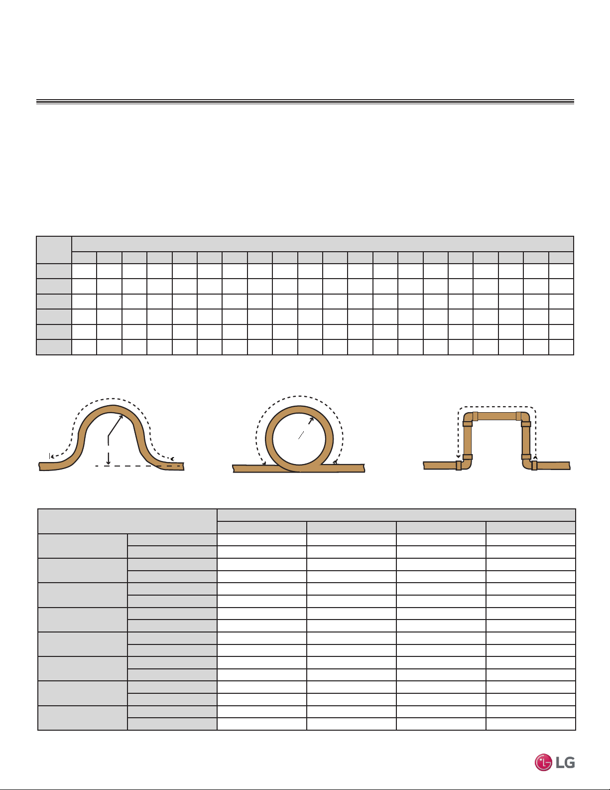
When creating an expansion joint, the joint height should be a
minimum of two times the joint width. Although different types of
expansion arrangements are available, the data for correctly sizing
an Expansion Loop is provided in Table 1010. Use soft copper with
long radius bends on longer runs or long radius elbows for shorter
pipe segments. Using the anticipated linear expansion (LE) distance
calculated, look up the Expansion Loop or U-bend minimum design
dimensions. If other types of expansion joints are chosen, design per
ASTM B-88 Standards.
LE = C x L x (T
r
– T
a
) x 12
LE = Anticipated linear tubing expansion (in.)
C = Constant (For copper = 9.2 x 10
-6
in./in.°F)
L = Length of pipe (ft.)
T
R
= Refrigerant pipe temperature (°F)
T
a
= Ambient air temperature (°F)
12 = Inches to feet conversion (12 in./ft.)
Copper Expansion and Contraction
26
Multi F Standard Wall-Mounted Indoor Unit
Due to our policy of continuous product innovation, some specifications may change without notification.
©LG Electronics U.S.A., Inc., Englewood Cliffs, NJ. All rights reserved. “LG” is a registered trademark of LG Corp.
MA
X
MUL
TI
F
MUL
TI
F
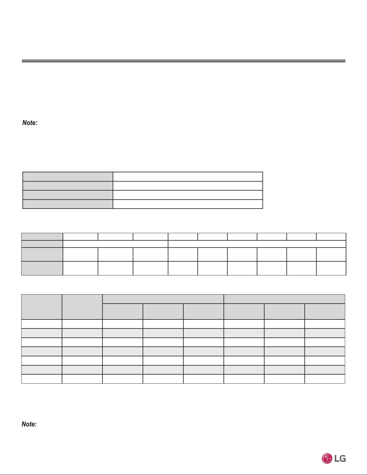
See table below for precalculated anticipated expansion for various pipe sizes and lengths of refrigerant tubing.
To find the anticipated expansion value:
1. From the table below, find the row corresponding with the actual feet of the straight pipe segment.
2. Estimate the minimum and maximum temperature of the pipe.
3. In the column showing the minimum pipe temperature, look up the anticipated expansion distance corresponding to the segment length.
Do the same for the maximum pipe temperature.
4. Calculate the difference in the two expansion distance values. The result will be the change in pipe length.
Pipe
Length
1
Fluid Temperature °F
35° 40° 45° 50° 55° 60° 65° 70° 75° 80° 85° 90° 95° 100° 105° 110° 115° 120° 125° 130°
10 0.04 0.04 0.05 0.06 0.06 0.07 0.08 0.08 0.09 0.09 0.10 0.10 0.11 0.11 0.11 0.12 0.13 0.14 0.15 0.15
20 0.08 0.08 0.10 0.12 0.13 0.14 0.15 0.16 0.17 0.18 0.19 0.20 0.21 0.22 0.22 0.23 0.26 0.28 0.29 0.30
30 0.12 0.12 0.15 0.18 0.20 0.21 0.23 0.24 0.26 0.27 0.29 0.30 0.32 0.33 0.32 0.35 0.39 0.42 0.44 0.45
40 0.16 0.16 0.20 0.24 0.26 0.28 0.30 0.32 0.34 0.36 0.38 0.40 0.42 0.44 0.43 0.46 0.52 0.56 0.58 0.60
50 0.20 0.20 0.25 0.30 0.33 0.35 0.38 0.40 0.43 0.45 0.48 0.50 0.53 0.55 0.54 0.58 0.65 0.70 0.73 0.75
60 0.24 0.24 0.30 0.36 0.39 0.42 0.45 0.48 0.51 0.54 0.57 0.60 0.63 0.66 0.65 0.69 0.78 0.84 0.87 0.90
Table 15: Linear Thermal Expansion of Copper Tubing in Inches
1
Pipe length baseline temperature = 0°F. "Expansion of Carbon, Copper and Stainless Steel Pipe," The Engineers' Toolbox, www.engineeringtoolbox.com.
Figure 18: Coiled Expansion Loops and Offsets
Large Tubing U-bend (>3/4 in.) Loop Small Tubing U-bend (<3/4 in.)
R
L
R
L
L
Anticipated Linear
Expansion (LE) (inches)
Nominal Tube Size (OD) inches
1/4 3/8 1/2 3/4
1/2
R
1
6 7 8 9
L
2
38 44 50 59
1
R
1
9 10 11 13
L
2
54 63 70 83
1-1/2
R
1
11 12 14 16
L
2
66 77 86 101
2
R
1
12 14 16 19
L
2
77 89 99 117
2-1/2
R
1
14 16 18 21
L
2
86 99 111 131
3
R
1
15 17 19 23
L
2
94 109 122 143
3-1/2
R
1
16 19 21 25
L
2
102 117 131 155
4
R
1
17 20 22 26
L
2
109 126 140 166
Table 16: Radii of Coiled Expansion Loops and Developed Lengths of Expansion Offsets
GENERAL INSTALLATION GUIDELINES
Refrigerant Piping
27
Installation Manual
Due to our policy of continuous product innovation, some specifications may change without notification.
©LG Electronics U.S.A., Inc., Englewood Cliffs, NJ. All rights reserved. “LG” is a registered trademark of LG Corp.
MA
X
MUL
TI
F
MUL
TI
F
Pipe Supports
Figure 19: Installing an Insert Into
a Concrete Beam.
GENERAL INSTALLATION GUIDELINES
Refrigerant Piping
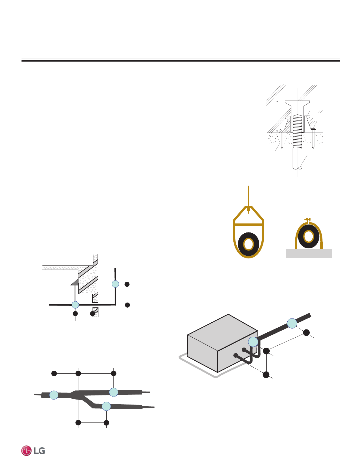
Inserts and Pipe Supports
Inserts
An insert can be installed into a floor or beam before the concrete sets so that fittings such as ducts,
pipes, or suspension bolts can be added at a later time. Decide where the inserts should be placed
before support installation.
Concrete Beam
Insert
Suspension Bolt
Anti-vibration Material
Nail
Figure 20: Pipe Hanger Details.
A
B
A + B ~ 12" – 19"
Max. 12" Max. 12"
Max. 12"
Figure 21: Typical Pipe Support Location—Change
in Pipe Direction.
Max. 12"
~ 12" – 19"
Pipe supports should never touch the pipe wall; supports should be installed outside
(around) the primary pipe insulation jacket. Insulate the pipe before installing the sup-
ports. Pipe supports are field-provided and must meet local code. If local codes do not
specify pipe support spacing, install pipe supports a maximum of 5 feet on center for
straight segments of pipe up to 3/4” outside diameter size.
Wherever the pipe changes direction, place a hanger within twelve (12) inches on one
side and within twelve to nineteen (12 to 19) inches of the bend on the other side. Sup-
port piping at indoor units as shown. Support Y-Branch fittings as shown.
Note:
The pipe system must be adequately supported to avoid pipe sagging. Sagging pipes become oil traps that
lead to equipment malfunction.
Figure 22: Pipe Support at Indoor Unit.
Figure 23: Pipe Support at Y-branch Fitting.
28
Multi F Standard Wall-Mounted Indoor Unit
Due to our policy of continuous product innovation, some specifications may change without notification.
©LG Electronics U.S.A., Inc., Englewood Cliffs, NJ. All rights reserved. “LG” is a registered trademark of LG Corp.
MA
X
MUL
TI
F
MUL
TI
F
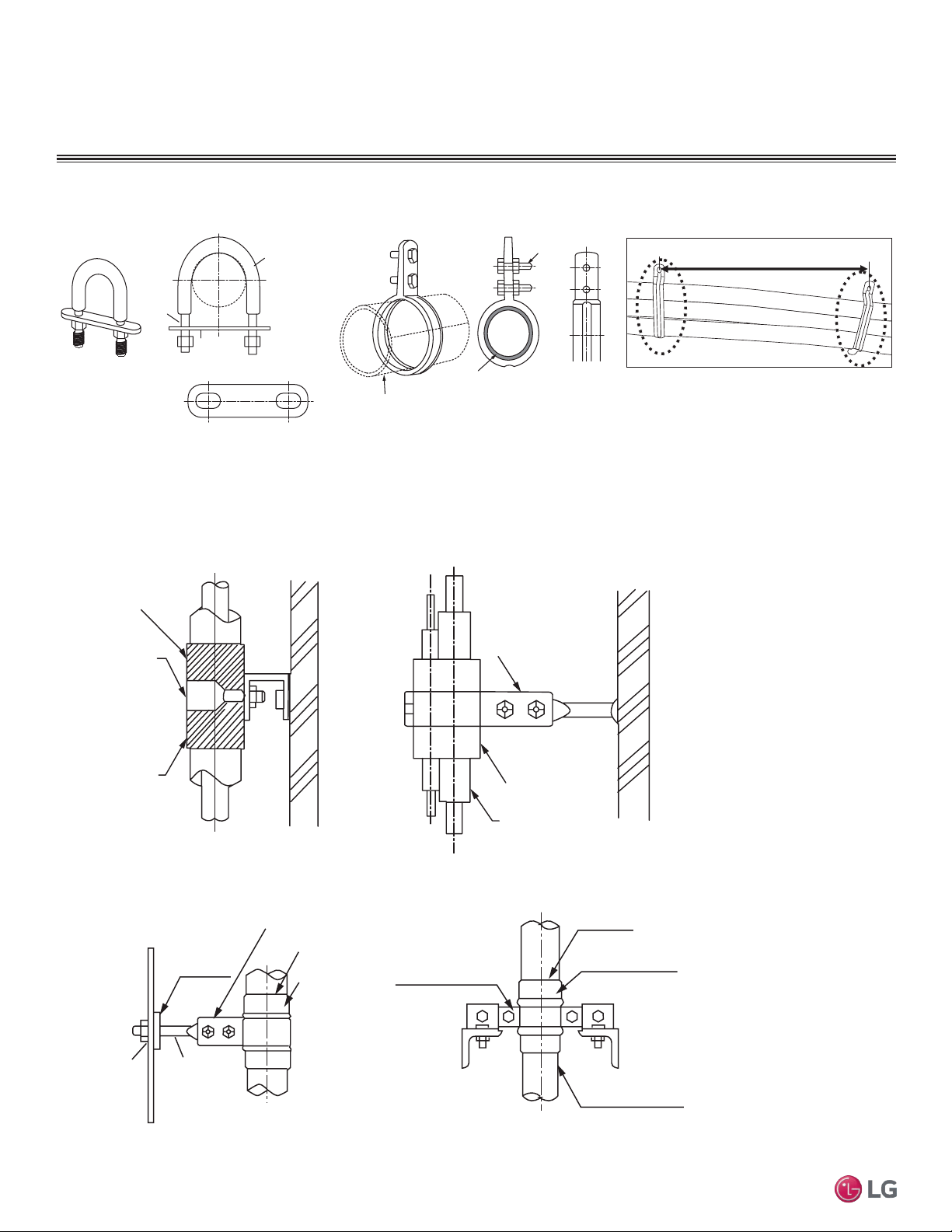
Examples of Supports
Bolt
1.5t
Plate
Insulation
Bolt
PVC
PVC
Figure 24: U-Bolt Support with Insulation. Figure 25: O-Ring Support with Insulation.
To prevent
insulation from
pressing and
lagging, use a cover.
Sheathing
Sheathing
O-Ring
Band
Lags
Note:
Do not compress the insulation with the saddle-type support. If the insulation is compressed, it may tear open and allow condensation to
generate during product operation.
Welding
Refrigerant Pipe
Insulated
Support Band
Insulated
Support Band
Down
Stop
Welding
Plate Nut
Hexagonal Nut
O-ring Band
Support at Intervals Between 5 and 6-3/4 Feet
Figure 26: Saddle-Type Support.
Figure 27: U-Bolt Support with an Insulated Pipe. Figure 28: O-Ring Band Support with an Insulated Pipe.
Figure 29: One-Point Down-Stop Support (>441 lbs.).
Figure 30: Two-Point Down-Stop Support.
Refrigerant Piping
GENERAL INSTALLATION GUIDELINES
29
Installation Manual
Due to our policy of continuous product innovation, some specifications may change without notification.
©LG Electronics U.S.A., Inc., Englewood Cliffs, NJ. All rights reserved. “LG” is a registered trademark of LG Corp.
MA
X
MUL
TI
F
MUL
TI
F
40 in40 in
A
B
D
F
G
B
G
D
B
H
I
J
A
E
B
I
A
B
D
C
Inside wall (concealed)
Floor (fire-resistance)
Area between fire-resistant
insulation and boundary wall
Roof pipe shaft
Outside wall
Outside wall (exposed)
Sleeve
Insulation
Lagging
Caulk
Band
Water-resistant layer
Sleeve with edge
Lagging
Mortar or other fire-resistant caulk
Fire-resistant insulation
When filling an access hole with mortar, cover the
area with steel plate so that the insulation will not
fall through. For this area, use fire-resistant
materials for both the insulation and cover. (Vinyl
cover should not be used.)
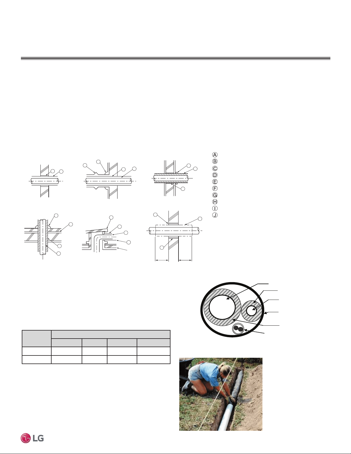
Pipe Sleeves at Penetrations
LG requires that all pipe penetrations through walls, floors, and
pipes buried underground be routed through a properly insulated
sleeve that is sufficiently sized to provide free movement of the pipe
and does not compress the insulation. Route underground refriger-
ant pipe inside a protective sleeve to prevent insulation deteriora-
tion. Follow federal, state, and local regulations and codes when
choosing a sleeve type.
Figure 31: Pipe Sleeve Options.
For example:
Diameter of Gas Piping: 1/2"
Diameter of Liquid Piping: 1/4"
Thickness of Gas Piping Insulation: 0.4" x 2
Thickness of Liquid Piping Insulation: 0.4" x 2
Surplus: 0.8"
Sleeve diameter (total): 3.1" minimum
Note:
Pipe diameter plus insulation thickness determines wall
penetration diameter.
Underground Refrigerant Piping
Route refrigerant pipe installed underground inside a vapor tight pro-
tective sleeve to prevent insulation deterioration and water infiltra-
tion. Refrigerant pipe installed inside underground casing must be
continuous without any joints. Underground refrigerant pipe must be
located at a level below the frost line.
Figure 32: Typical Arrangement of Refrigerant Pipe
and Cable(s) in a Utility Conduit.
Table 17: Utility Conduit Sizes.
1
OD pipe diameter in inches; Values in parenthesis () indicate OD of pipe with insulation
jacket.
2
Diameter of pipe with insulation. Thickness of pipe insulation is typical. Actual required
thickness may vary based on surrounding ambient conditions and should be calculated
and specified by the design engineer.
3
Insulation thickness (value in parenthesis) = 3/8 inch.
4
Insulation thickness (value in parenthesis) = 1 inch.
5
Insulation thickness (value in parenthesis) = 3/4 inch.
Figure 33: Underground Refrigerant Piping.
Liquid
Pipe
1
Vapor Pipe
1
3/8 (1-1/8
2,3
) 1/2 (2.0
2,5
) 5/8 (2-1/8
2,5
) 3/4 (2-1/4
2,5
)
1/4 (1.0)
3
4 4 4 4
3/8 (1-1/8)
3
4 4 4 5
Vapor Line
Liquid Line
Min. 18 Gauge
Cable
Power/Communication
Pi
p
e Sleeve
Insulation Material
Insulation
Material
GENERAL INSTALLATION GUIDELINES
Refrigerant Piping
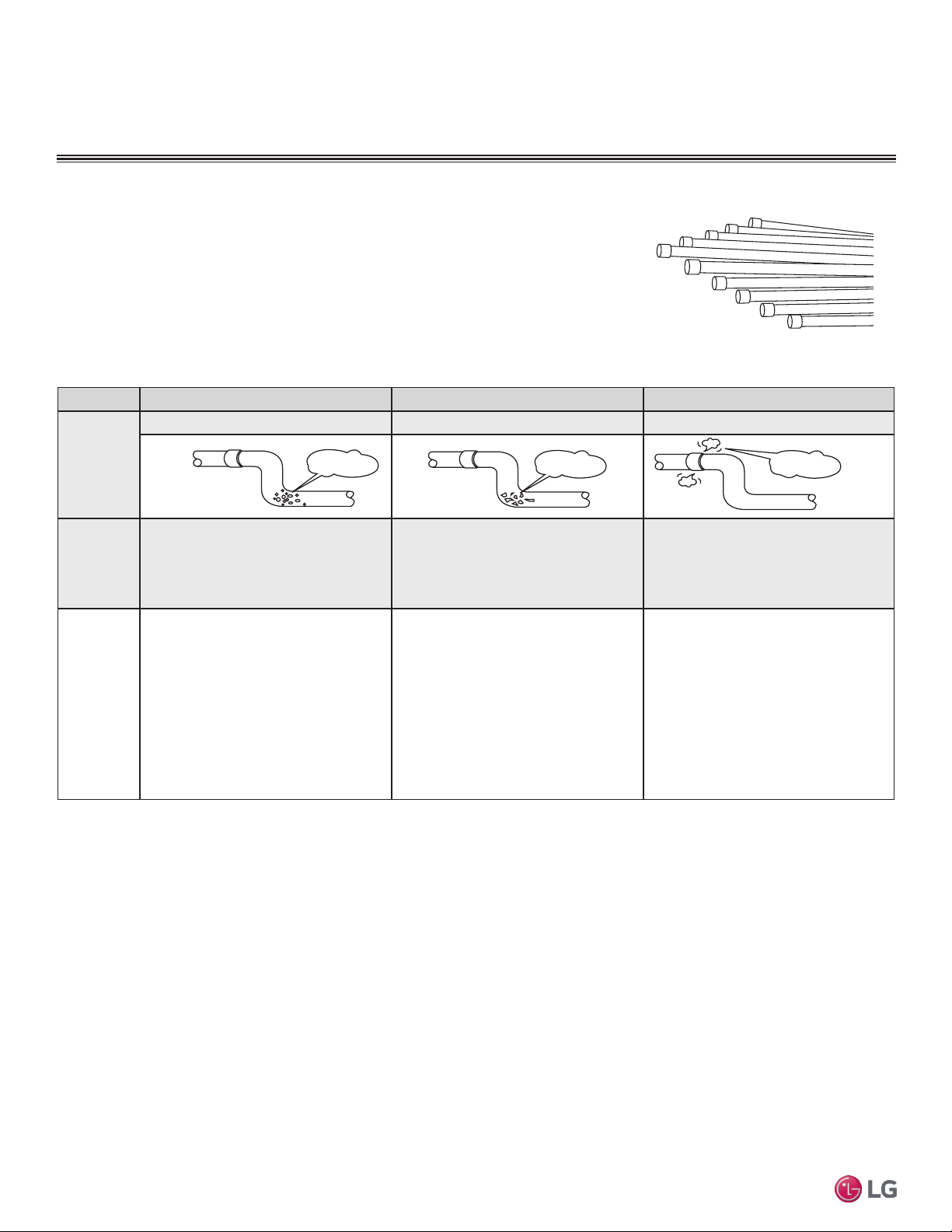
30
Multi F Standard Wall-Mounted Indoor Unit
Due to our policy of continuous product innovation, some specifications may change without notification.
©LG Electronics U.S.A., Inc., Englewood Cliffs, NJ. All rights reserved. “LG” is a registered trademark of LG Corp.
MA
X
MUL
TI
F
MUL
TI
F
Pipes used for the refrigerant piping system must include the specified thickness, and the
interior must be clean.
While handling and storing, do not bend or damage the pipes, and take care not to contami-
nate the interior with dust, moisture, etc. See Table 18 for care of piping.
Dry Clean Airtight
Principles No moisture should be inside the piping. No dust should be inside the piping. No leaks should occur.
Problems
Caused
- Significant hydrolysis of refrigerant oil.
- Refrigerant oil degradation.
- Poor insulation of the compressor.
- System does not operate properly.
- EEVs, capillary tubes are clogged.
- Refrigerant oil degradation.
- Poor insulation of the compressor.
- System does not operate properly.
- EEVs and capillary tubes become
clogged.
- Refrigerant gas leaks / shortages.
- Refrigerant oil degradation.
- Poor insulation of the compressor.
- System does not operate properly.
Solutions
- Remove moisture from the piping.
- Piping ends should remain capped until
connections are complete.
- Do not install piping on a rainy day.
- Connect piping properly at the unit’s side.
- Remove caps only after the piping is
cut, the burrs are removed, and after
passing the piping through the walls.
- Evacuate system to a minimum of 500
microns and ensure the vacuum holds at
that level for 24 hours
- Remove dust from the piping.
- Piping ends should remain capped until
connections are complete.
- Connect piping properly at the side of
the unit.
- Remove caps only after the piping is cut
and burrs are removed.
- Retain the cap on the piping when
passing it through walls, etc.
- Test system for air tightness.
- Perform brazing procedures that comply
with all applicable standards.
- Perform flaring procedures that comply
with all applicable standards.
- Perform flanging procedures that
comply with all applicable standards.
- Ensure that refrigerant lines are pressure
tested to 550 psig.
Moisture
Dust
Leaks
Figure 34: Keep Piping Capped While Storing
Table 18: Three Principles of Refrigerant Piping
Piping Materials and Handling
GENERAL INSTALLATION GUIDELINES
Piping Materials and Handling
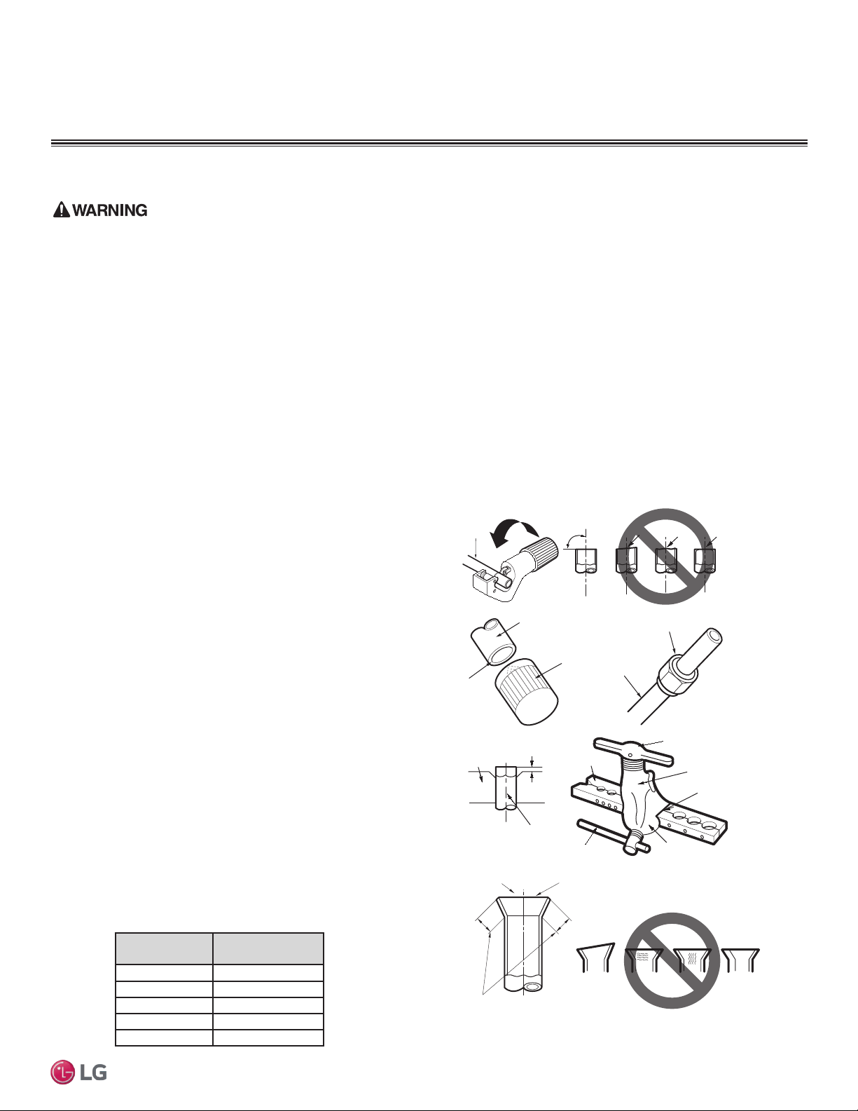
31
Installation Manual
Due to our policy of continuous product innovation, some specifications may change without notification.
©LG Electronics U.S.A., Inc., Englewood Cliffs, NJ. All rights reserved. “LG” is a registered trademark of LG Corp.
MA
X
MUL
TI
F
MUL
TI
F
• Do not allow the refrigerant to leak during brazing; if refrigerant combusts, it generates a toxic gas which can cause physical injury or death.
• Do not braze in an enclosed location, and always test for gas leaks before/after brazing. Gas leaks can cause physical injury or death.
• After brazing, check for refrigerant gas leaks. Refrigerant gas leaks can cause physical injury or death.
• When selecting flare fittings, always use a 45° fitting rated for use with high pressure refrigerant R410A. Failure to do so may result in
refrigerant leaks which in turn could result in personal injuries or death from oxygen depletion. Selected fittings must also comply with local,
state, or federal standards.
Creating a Flare Fitting
Note:
One of the main causes of refrigerant leaks is defective ared connections. Be sure to properly form the are connections.
1. Cut the pipe to length.
• Measure the distance between the indoor unit and the
outdoor unit.
• Cut the pipes a little longer than measured distance.
• Cut the cable 4.9 ft longer than the pipe length.
2A. Remove the burrs.
• Completely remove all burrs from pipe ends.
• When removing burrs, point the end of the copper pipe
down to avoid introducing foreign materials in the pipe.
2B. Slide the flare nut onto the copper tube.
3. Flaring the pipe end.
• Use the proper size aring tool to nish ared connections
as shown.
• Refer to the diagram in step 3 of Figure 35 and the dimen-
sions in Table 19 for positioning the pipe in the aring tool.
• ALWAYS create a 45° are when working with R410A. See
Warning on this page.
4. Carefully inspect the flared pipe end.
• Compare the are with the illustration in step 4 of Figure 35.
• If the are is defective, cut it off and re-do procedure.
• If are looks good, blow clean the pipe with dry nitrogen.
Pipe Outside
Diameter (inch)
“A” Measurement
(inch)
1/4 0.04 – 0.5
3/8 0.06 – 0.7
1/2 0.06 – 0.7
5/8 0.06 – 0.7
3/4 0.07 – 0.8
Table 19: Flare “A” Measurement
Piping Preparation
Note:
1. If piping becomes kinked due to excessive bending, do not use the pipe.
2. Braze the pipes to the service valve pipe stub of the outdoor unit.
Figure 35: Creating a Flare Fitting
Copper
tube
90°
Slanted Uneven Rough
Pipe
Reamer
Point
down
Flare nut
Copper
tube
Bar
Copper pipe
Clamp handle
Red arrow
Cone
Yoke
Handle
Bar
"A"
Slanted
Inside is shiny with no scratches
Smooth
Even length
Damaged
surface
Cracked Uneven
thickness
Incorrect Flares
1.
2A. 2B.
3.
4.
PIPING CONNECTIONS
Piping Preparation
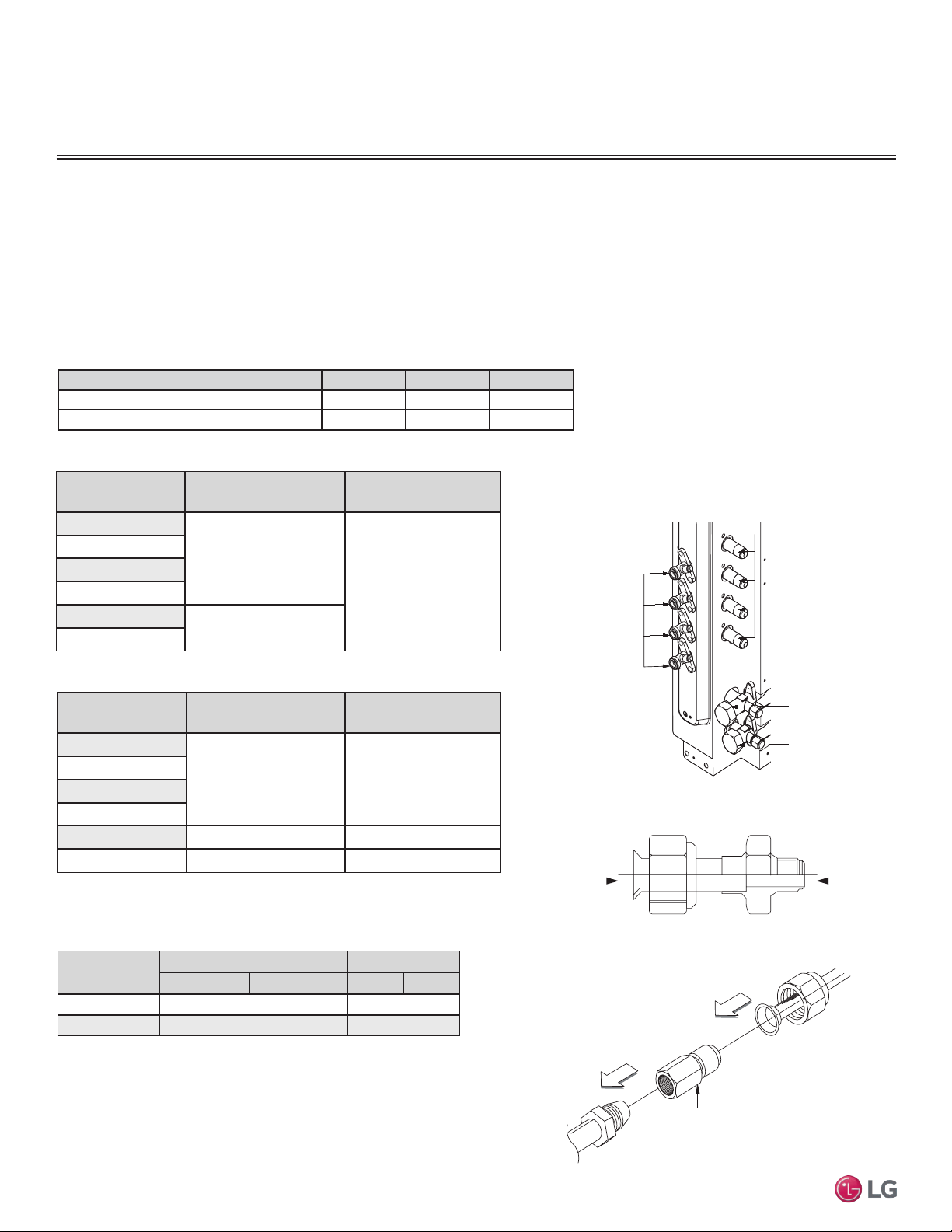
32
Multi F Standard Wall-Mounted Indoor Unit
Due to our policy of continuous product innovation, some specifications may change without notification.
©LG Electronics U.S.A., Inc., Englewood Cliffs, NJ. All rights reserved. “LG” is a registered trademark of LG Corp.
MA
X
MUL
TI
F
MUL
TI
F
Table 20: Outdoor Unit Piping Connections.
Figure 36: Multi F Refrigerant Pipe Connections
(LMU36CHV shown as example).
Avoid Pipe Damage
• When routing eld-provided piping, avoid damaging the outdoor unit from excessive vibration.
• Correctly route the piping so it does not make contact with mounting bolts. Allow room for eld installation.
• Properly insulate the liquid and gas lines separately up to the point of connection at the unit frame.
• See table below for Multi F outdoor unit connection types.
Main gas
valve
Main liquid
valve
Gas Piping Connections
Liquid
Piping
Connection
s
A-UNIT
B-UNIT
C-UNIT
D-UNIT
Connection sockets (included as a factory-supplied accessory with the indoor
units) may need to be used when piping the indoor units to the outdoor unit.
Indoor Unit
Capacity
Vapor (in., OD) Liquid (in., OD)
A B A B
18,000 Btu/h Ø3/8 → Ø1/2, Ø1/2 → Ø5/8 Ø1/4 → Ø3/8
24,000 Btu/h Ø3/8 → Ø1/2 N/A
A
B
Flare
to
Indoor
Unit
Flare
to
Outdoor
Unit
Indoor Unit Capac-
ity
Vapor Line Size
(in., OD)
Liquid Line Size
(in., OD)
7,000 Btu/h
Ø3/8
Ø1/4
9,000 Btu/h
12,000 Btu/h
15,000 Btu/h
18,000 Btu/h
Ø1/2
24,000 Btu/h
1. Align the center of the piping sections and tighten the flare nut by
hand.
2. Tighten the flare nut with a torque wrench, using the arrows on
the wrench as a guide, until a click is heard.
Multi F Outdoor Unit to Indoor Unit Piping Connections
Outdoor Unit Piping Connections LMU18CHV LMU24CHV LMU36CHV
Liquid Line Connection (in., OD) x Qty. 1/4 x 2 1/4 x 3 1/4 x 4
Vapor Line Connection (in., OD) x Qty. 3/8 x 2 3/8 x 3 3/8 x 4
Table 21: Indoor Unit Pipe Sizes.
Table 22: Indoor Unit Piping Connections.
Figure 37: Connection Socket Diagram.
Using the Connection Socket
Connection Socket
(Factory-supplied with
the indoor unit)
Figure 38: Performing Connections.
Indoor Unit Capac-
ity
Vapor Line Connection
(in., OD)
Liquid Line Connection
(in., OD)
7,000 Btu/h
Ø3/8 Ø1/4
9,000 Btu/h
12,000 Btu/h
15,000 Btu/h
18,000 Btu/h Ø5/8 Ø3/8
24,000 Btu/h Ø1/2 Ø1/4
Table 23: Connection Socket Dimensions.
IDU to ODU
PIPING CONNECTIONS
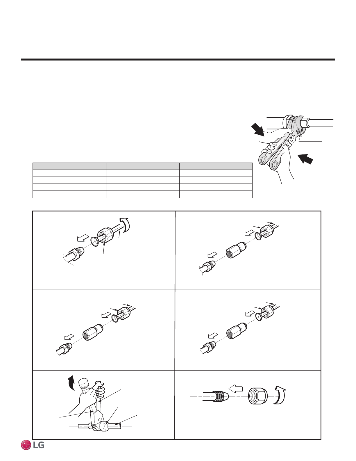
33
Installation Manual
Due to our policy of continuous product innovation, some specifications may change without notification.
©LG Electronics U.S.A., Inc., Englewood Cliffs, NJ. All rights reserved. “LG” is a registered trademark of LG Corp.
MA
X
MUL
TI
F
MUL
TI
F
Flare nut
Piping
1. 3/8 in. to 3/8 in. Connection
2. 3/8 in. to 1/2 in.
Connection
Flare side to
branch distribution unit or ODU
Flare side to indoor unit
Ø3/8 in.
Flare side to indoor unit or
pipe to indoor unit
Ø1/2 in.
Connection socket
Flare nut
Piping
Ø3/8 in.
Ø3/8 in.
Spanner
Field Piping
Flare nut
Torque
wrench
3. 1/2 in. to 5/8 in.
Connection
Ø5/8 in.
Connection socket
Flare nut
Piping
Ø1/2 in.
4. 1/4 in. to 3/8
Connection
Flare side to indoor unit
Ø3/8 in.
Connection socket
Flare nut
Piping
Ø1/4 in.
Flare
side to
branch distribution unit or ODU
Flare side to indoor unit
Flare
side pipe
from branch distribution unit or ODU
Flare
side to
branch distribution unit or ODU
Multi F System Piping Connections
Figure 39: Possible Outdoor Unit or Branch Distribution Unit to Indoor Unit Connections.
1. When connecting the flare nuts, coat the flare (inside and outside) with polyvinyl ether (PVE)
refrigeration oil only.
2. Align the center of the piping sections and tighten the flare nut by hand.
3. Tighten the flare nut with a torque wrench and a backup wrench until a click is heard.
4. Wrap insulation around the connection.
5. If it is necessary to loosen the flare nuts, always use two wrenches to do so.
PIPING CONNECTIONS
IDU to ODU
Union
Figure 40: Tightening the Flare Nuts.
Pipe size (Inches O.D.) Tightening torque (ft-lbs) Width of the are (A [inches])
1/4Ø 13.9 - 18 1/8
3/8Ø 24.5 - 30.3 1/8
1/2Ø 39.7 - 47.7 1/8
5/8Ø 45.5 - 59.2 1/16
Table 24: Tightening Torque for Flare Nuts.
Note:
Do not use polyolyester (POE) or any other type of mineral oil as a thread lubricant. These lubricants are not compatible with PVE oil used in this
system and create oil sludge leading to equipment damage and system malfunction.
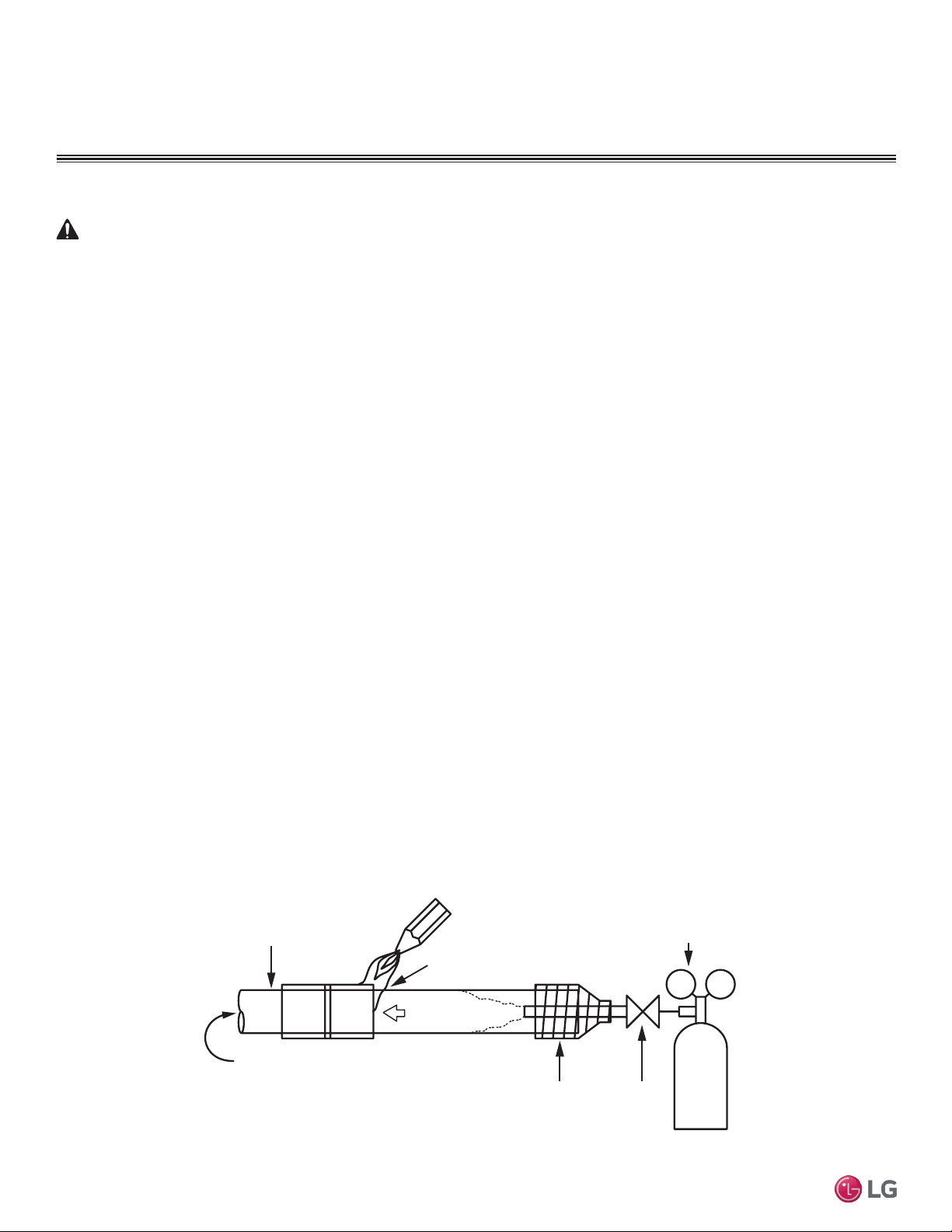
34
Multi F Standard Wall-Mounted Indoor Unit
Due to our policy of continuous product innovation, some specifications may change without notification.
©LG Electronics U.S.A., Inc., Englewood Cliffs, NJ. All rights reserved. “LG” is a registered trademark of LG Corp.
MA
X
MUL
TI
F
MUL
TI
F
Figure 41: Using Nitrogen Gas During Brazing
Refrigerant Safety
ASHRAE Standards 15-2010 and 34-2010 offer guidelines that address refrigerant safety and the maximum allowable concentration of
refrigerant in an occupied space. Refrigerant will dissipate into the atmosphere, but a certain volume of air is required for this to occur safely.
For R410A refrigerant, the maximum allowable concentration of refrigerant is twenty-six (26) lbs. per 1,000 cubic feet of an occupied space.
Buildings with twenty-four (24) hour occupancy allow half of that concentration.
1
ASHRAE Standards 15 and 34 assume that if a system develops a leak, its entire refrigerant charge will dump into the area where the leak
occurs. To meet ASHRAE Standards 15 and 34, calculate the refrigerant concentration that may occur in the smallest room volume on the
system, and compare the results to the maximum allowable concentration number.
1
Also consult state and local codes in regards to refriger-
ant safety.
WARNING
Verify the maximum refrigerant concentration level in the space where the indoor unit will be mounted meets the concentration limit for the application.
1
Information about ASHRAE Standard 15-2010/34-2010 and addenda current as of the date of this publication.
Auxiliary
Valve
Tape
(no air bubbles)
Do not block outlet side.
When pressure inside pipe
is above atmospheric pressure,
pinhole leaks can occur
Refrigerant Pipe
Welding Point
Regulator
Nitrogen gas
3.0 psi or less
Nitrogen
Gas
Tank
Brazing
Note:
It is imperative to keep the piping system free of contaminants and debris such as copper burrs, slag, or carbon dust during installation.
1. All joints are brazed in the field. Multi V IV refrigeration system components contain very small capillary tubes, small orifices, electronic
expansion valves, oil separators, and heat exchangers that can easily become blocked. Proper system operation depends on the
installer using best practices and utmost care while assembling the piping system.
• Store pipe stock in a dry place and keep stored pipe capped and clean.
• Purge all pipe sections clean with dry nitrogen prior to assembly.
2. Proper system operation depends on the installer using best practices and the utmost care while assembling the piping system.
• Use adapters to assemble different sizes of pipe.
• Always use a non-oxidizing material for brazing. Do not use ux, soft solder, or anti-oxidant agents. If the proper material is not used,
oxidized lm may accumulate and clog or damage the compressors. Flux can harm the copper piping or refrigerant oil.
• Use a tubing cutter; do not use a saw to cut pipe. De-bur and clean all cuts before assembly.
3. Brazing joints:
• Use a dry nitrogen purge operating at a minimum pressure of three (3) psig and maintain a steady ow.
• Use a 15% silver phosphorous copper brazing alloy to avoid overheating and produce good ow.
• Protect isolation valves, electronic expansion valves, and other heat-sensitive control components from excessive heat with a wet rag or
heat barrier spray.
IDU to ODU
PIPING CONNECTIONS
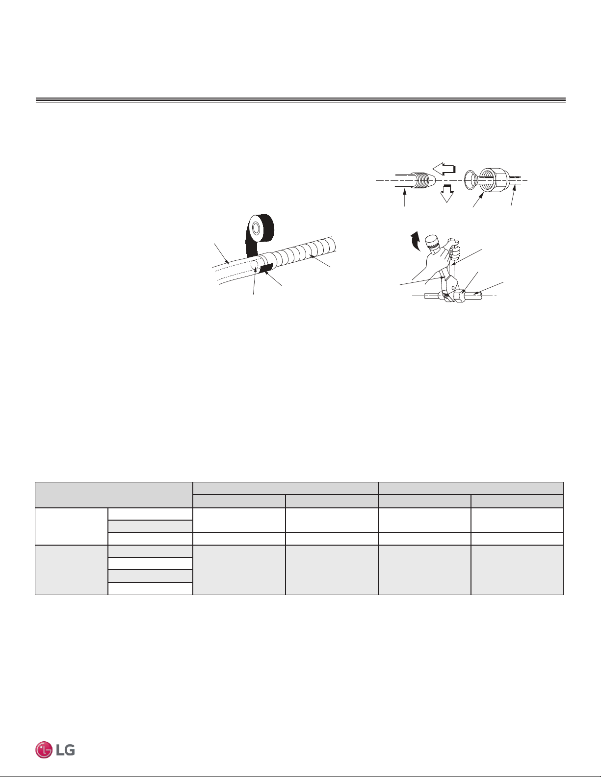
35
Installation Manual
Due to our policy of continuous product innovation, some specifications may change without notification.
©LG Electronics U.S.A., Inc., Englewood Cliffs, NJ. All rights reserved. “LG” is a registered trademark of LG Corp.
MA
X
MUL
TI
F
MUL
TI
F
Note:
Follow locals codes when selecting EPDM insulation wall thickness. Thickness in Table 25 is based on heat conductivity of 0.61 Btu/in/h/ft2/°F.
Table 25: Insulation Guidelines for Typical and Special Circumstances.
Classication
Air-conditioned location Non-air conditioned location
1. Typical location 2. Special location 3. Typical location 4. Special location
Liquid pipe
ø1/4 inches
1/2 inches 1/2 inches 1/2 inches 1/2 inches
ø3/8 inches
≥ø1/2 inches 1/2 inches 1/2 inches 1/2 inches 1/2 inches
Vapor pipe
ø3/8 inches
1/2 inches 3/4 inches 3/4 inches 1 inch
ø1/2 inches
ø5/8 inches
ø3/4 inches
1. Air-conditioned, Typical location
• When piping passes through an indoor area where the indoor unit operates, such as an apartment, classroom, ofce, mall, hospital, etc.
2. Air-conditioned, Special location
• When the location is air conditioned, but has severe temp/humidity difference due to high ceilings, such as a church, auditorium, theater, etc.
• When the location is air conditioned, but internal temperature/humidity are high, such as a bathroom, swimming pool, locker room, etc.
3. Non-air conditioned, Typical location
• When piping passes through an indoor area where the indoor unit does not operate, such as a hallway, dormitory, or school, etc.
4. Non-air conditioned, Special location (when both conditions listed below are present)
• When piping passes through an indoor area where the indoor unit does not operate
• When the humidity is high and there is no air ow in the location where the piping is installed
Piping Insulation
PIPING CONNECTIONS
Connecting the Indoor Unit Piping to the Field-Installed Piping
Note:
If the drain hose is routed inside a room,
add insulation to prevent condensation
from forming.
1. Center align the indoor unit piping (refrigerant and drain) and the
field-installed piping, then hand tighten the flare nut.
2. Tighten the flare nut with a torque wrench.
3. Attach the drain tube piping to the
indoor unit drain hose as shown.
Indoor unit piping
Flare nut Field-installed
piping
Spanner
Field-installed
piping
Flare nut
Torque
wrench
Figure 42: Indoor Unit to Field-Installed Piping Connection.
Narrow tape
Adhesive
Drain extension
Indoor unit
drain hose
Figure 43: Extending the Drain Hose.
Refrigerant Piping System Insulation
All refrigerant piping including Y-branch connections, field-provided isolation ball valves, service valves, and elbows must be completely
insulated using closed cell pipe insulation (up to the indoor unit piping connections). To prevent heat loss/heat gain through the refrigerant
piping, all refrigerant piping including liquid lines and vapor lines must be insulated separately. Insulation must be a minimum 1/2″ thick, and
thickness may need to be increased based on ambient conditions and local codes. Insulation for field-installed refrigerant piping must have
a minimum heat resistance of 248°F. Table 25 lists minimum wall thickness requirements for Ethylene Propylene Diene Methylene (EPDM)
insulation.
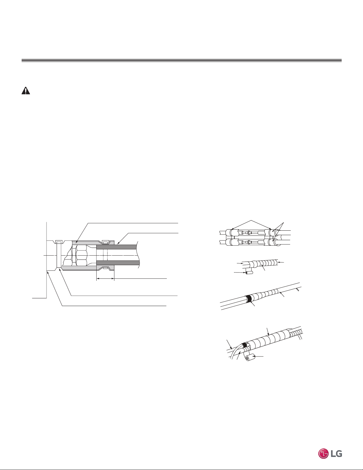
36
Multi F Standard Wall-Mounted Indoor Unit
Due to our policy of continuous product innovation, some specifications may change without notification.
©LG Electronics U.S.A., Inc., Englewood Cliffs, NJ. All rights reserved. “LG” is a registered trademark of LG Corp.
MA
X
MUL
TI
F
MUL
TI
F
PIPING CONNECTIONS
IDU to ODU
Installing Refrigerant Piping Insulation
WARNING
Ensure all refrigerant piping is insulated. Exposed refrigerant piping may cause burns if touched.
Wrap all refrigerant and condensate piping including field-provided isolation ball valves and flexible pipe connection kits
provided by LG. All pipes must be insulated and each pipe must be separately wrapped. Any exposed piping may gener-
ate condensate or will cause burns if touched. Sufficiently insulate all cold surfaces to prevent moisture forming.
Ensure insulation material fits snugly against the refrigeration pipe with no air space between the pipe surface and the
surrounding insulation.
Protect insulation inside hangers and supports with a second insulation layer. Ensure insulation on all pipe passing
through pipe hangers, inside conduit, and/or sleeves is not compressed.
Glue all insulation joints with no air gaps. Be sure insulation material fits snugly against the refrigeration pipe with no air
space between it and the pipe. All pipe insulation exposed to the sun and outdoor elements must be properly protected
with PVC, aluminum vapor barrier, or alternatively placed in a weather-resistant enclosure such as a pipe rack with a top
cover; and must meet local codes. Pay special attention to insulating the pipes installed in a ceiling plenum.
Figure 44: Typical Refrigerant Line Flare Fitting Insulation Detail
No Clearance
Overlap Insulation Where the
Port and the Piping Meet
Insulation for Indoor Unit Port
(Field Supplied)
Insulation for Refrigerant
Piping (Field Supplied)
Insulation Clip (Field Supplied)
Bands
Insulation
Narrow tape
Field-supplied
piping
Wide tape
Wrap with tape
Indoor unit
piping
Piping
Wrap with tape
Drain hose
Piping
Wide tape
1.
2.
3.
Figure 45: Insulating the Piping.
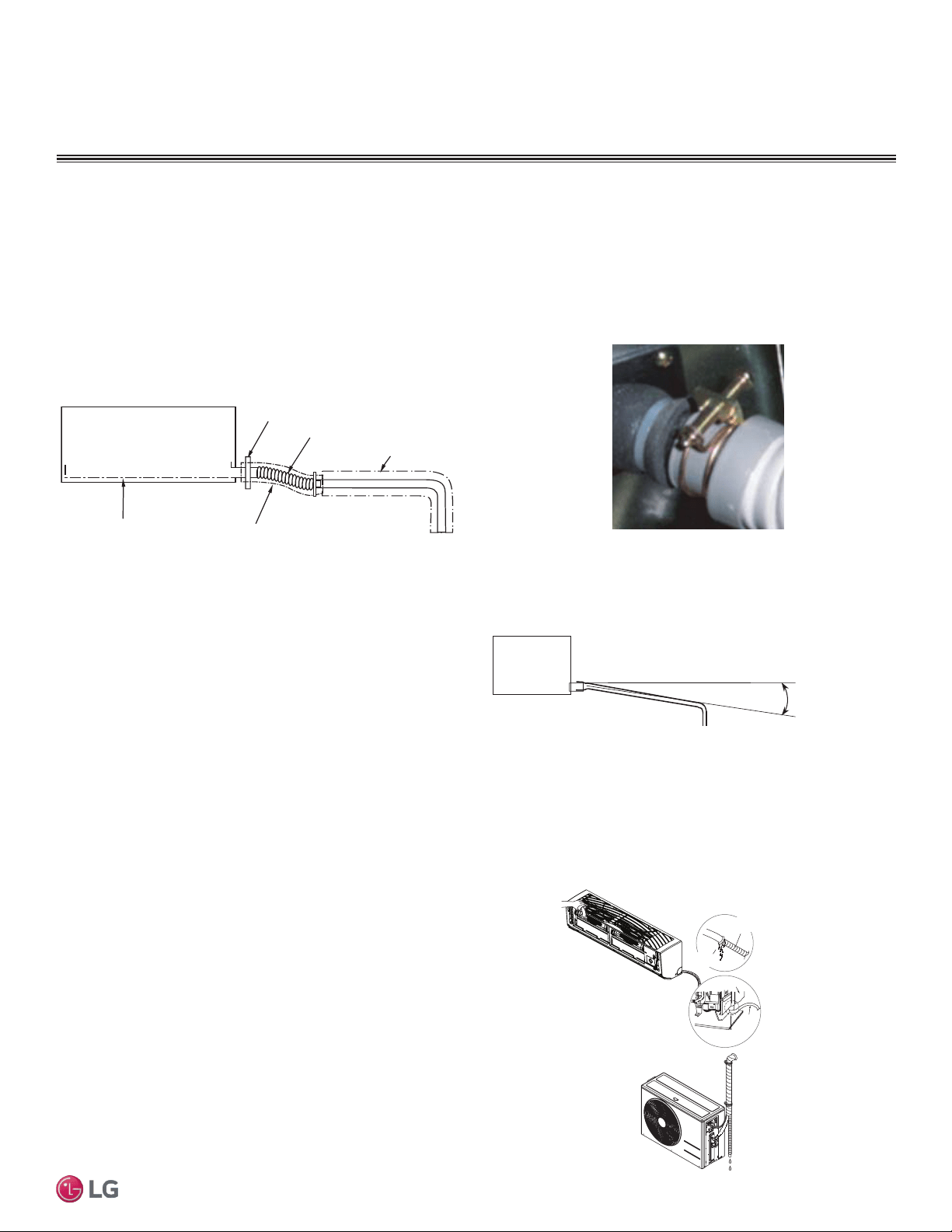
37
Installation Manual
Due to our policy of continuous product innovation, some specifications may change without notification.
©LG Electronics U.S.A., Inc., Englewood Cliffs, NJ. All rights reserved. “LG” is a registered trademark of LG Corp.
MA
X
MUL
TI
F
MUL
TI
F
Drain Pipe Insulation
Drain piping must have insulation a minimum of 7/32 inches thick.
1. Overlap the insulation at the connection of the field-installed piping and the indoor unit piping. Tape together so that no gaps exist.
2. Secure insulation to the rear piping housing section with vinyl tape.
3. Bundle the piping and drain hose with tape where they meet at the back of the indoor unit frame. Position the drain hose at the bottom of
the bundle (positioning the drain hose at the top of the bundle may cause the drain pan to overflow inside the indoor unit).
Drain Piping
Checking the Drainage System
Drain pan
Drain
hose
Drain hose
connection
Check for
leaks
Check for
leaks
Figure 46: Checking the Drainage System.
Drain Slope
Drain hose should point down so water can flow away easily. The
gradient for drain piping should be at least 1/50 to 1/100. Ensure any
holes through ceilings, walls, etc., are large enough to accommodate
both the drain piping and any insulation.
1. Pour water on the indoor unit evaporator. Do not use any other
liquid to test the drain.
2. Ensure the water flows through and out of the hose and away
from the indoor unit without leaking.
PIPING CONNECTIONS
Drain Piping
Indoor unit
Gradient of at least 1/50~1/100
Figure 47: Flexible Drain Hose
Connection.
Clamp the Flexible Drain Hose Connection
The standard wall-mounted indoor units have a factory-provided flexible pipe (13/16” O.D./ 5/8” I.D.) to drain condensate water. The
flexible pipe connects to field-provided drain pipe. Use materials that comply with local codes for drain pipe and insulation.
1. Install the flexible drain pipe as straight as possible; sharp angles may cause the pipe to deteriorate and may crack over time.
2. Connect the flexible drain pipe with a round clamp. If the flexible drain pipe is not
installed properly, water will leak from the connection.
3. Do not include a reverse slope in the drain connection.
Figure 48: Drain Piping Gradient Recommendation.
Metal clamp
Drain pan
Insulation
Flexible drain hose
Insulation
Figure 49: Indoor Unit with Gravity Drain.
38
Multi F Standard Wall-Mounted Indoor Unit
Due to our policy of continuous product innovation, some specifications may change without notification.
©LG Electronics U.S.A., Inc., Englewood Cliffs, NJ. All rights reserved. “LG” is a registered trademark of LG Corp.
MA
X
MUL
TI
F
MUL
TI
F
ELECTRICAL WIRING
• All power wiring and communication cable installation must be
performed by trained service providers working in accordance with
local, state, and National Electrical Code regulations related to
electrical equipment and wiring, and following the instructions in
this manual. Electric shock can cause physical injury or death.
• Undersized wiring may lead to unacceptable voltage at the unit and
may cause a fire hazard.
• Properly ground the Multi Zone outdoor and indoor units. Ground
wiring must always be installed by a trained technician Ground wiring
is required to prevent accidental electrical shock during current
leakage.
• Do not connect ground wire to refrigerant, gas, or water piping;
to lightning rods; to telephone ground wiring; or to the building
plumbing system. Failure to properly provide a National Electrical
Code-approved earth ground can result in electric shock, physical
injury or death.
• Verify that the branch switch and circuit breaker are set to OFF
before installing the wiring system. Electric shock can cause physi-
cal injury or death.
• Install appropriately sized breakers / fuses / overcurrent protection
switches and wiring in accordance with local, state, and National
Electrical Code regulations related to electrical equipment and wir-
ing, and following the instructions in this manual. Using an over-
sized breaker or fuse may result in electric shock, physical injury or
death.
• Consider ambient conditions (temperature, direct sunlight, inclem-
ent weather, etc.) when selecting, installing, and connecting the
power wiring.
• Properly ground the Multi Zone outdoor and indoor unit. Improperly
grounded wire can cause communication problems from electrical
noise, and motor current leakage. Ground wiring must always be
installed by a trained technician.
• If the system operates in reversed phase, it may damage the com-
pressors and other components.
• If there is a possibility of reversed phase, phase loss, momentary
blackout, or the power goes on and off while the system is
operating, install a field-supplied phase loss protection circuit.
• Do not connect ground wire to refrigerant, gas, or water piping;
to lightning rods; to telephone ground wiring; or to the building
plumbing system. Failure to properly provide a National Electrical
Code-approved earth ground can result in property damage and
equipment malfunction.
• Install appropriately sized breakers / fuses / overcurrent protection
switches and wiring in accordance with local, state, and National
Electrical Code regulations related to electrical equipment and
wiring, and following the instructions in this manual. Using an
oversized breaker or fuse may result in equipment malfunction and
property damage.
• Use only copper wiring that is stranded and shielded with the wires
separately insulated.
•
Do not use a multi-conductor cable with more than five (5)
wires in one (1) core.
• Power wiring and communications cable sizes must comply with
applicable federal UL / ETL, state, and local codes.
• Do not operate the air conditioning system until the refrigerant
piping installation is complete. Operating the system before refrig-
erant piping is finalized may damage the compressor.
• Install a ground wire for the outdoor units, indoor units, and branch
distribution units.
• Install a main shutoff switch or circuit breaker that interrupts all
power sources simultaneously (circuit breaker should be resistant
to electromagnetic currents).
• Use ring terminals to attach the wiring. Verify that all power wiring
and communications cable terminals are securely attached. Ensure
enough slack is included in the wiring and cables to avoid damag-
ing the connections.
• Use a conduit to protect the power wiring.
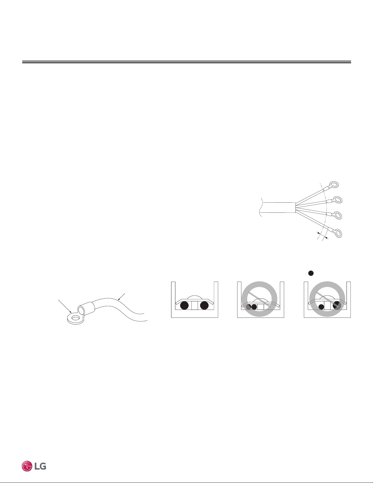
39
Installation Manual
Due to our policy of continuous product innovation, some specifications may change without notification.
©LG Electronics U.S.A., Inc., Englewood Cliffs, NJ. All rights reserved. “LG” is a registered trademark of LG Corp.
MA
X
MUL
TI
F
MUL
TI
F
ELECTRICAL WIRING
Ring Terminal
Power Wiring
Figure 50: Close up of a Typical Ring Terminal
:Copper Wire
Terminate multiple power wires of
the same gauge to both sides.
Do not terminate two wires on
one side.
Do not terminate different gauge
wires to a terminal block.
Figure 51: Proper and Improper Power Wiring Connections
Power Wiring Specications and Best Practices
Line Voltage Wiring and Communications Cable Installation
For both Multi F and Multi F MAX systems, line voltage is wired to the outdoor unit only. The outdoor unit will supply power to the
branch distribution units (Multi F MAX systems only) and the indoor units through the power wiring/communications cable.
Electrical Specifications
1. Multi F and Multi F MAX Outdoor Units: 1Ø, 208-230V, 60Hz
2. Indoor units/Branch Distribution Units (Multi F MAX systems only): 1Ø, 208-230V, 60Hz from ODU (Indoor units draw minimal power.)
3. Select power supply wire type and size based on NEC and local codes. Maximum voltage uctuation ±10% of the nameplate rated value.
4. Properly ground the outdoor unit per NEC and/or local code.
5. Use only copper wiring that is stranded and shielded with the wires separately insulated.
Power Wiring/Communications Cable Specications
• From Multi F Outdoor Units to Indoor Units = 4 x 18AWG
• From Multi F MAX Outdoor Units to Branch Distribution Units = 4 x 16AWG
• From Multi F MAX Branch Distribution Units to Indoor Units = 4 x 18AWG
• Maximum Allowable Temperature for Wiring: 194°F
• Indoor Unit(s) to Wired Controller: Three-core cable
• Multi F System Maximum Cable Length: 82 ft.
• Multi F MAX System Maximum Cable Length:
- Outdoor Unit to Branch Distribution Unit(s): 180.4 ft.
- Branch Distribution Unit(s) to Indoor Unit(s): 49.2 ft.
GN/YL
13/16 inch
Figure 52: Power Wiring and Communica-
tions Cable from the Multi F ODU to the
IDUs, or from the Multi F MAX ODU to the
BDUs and from the BD Unit to the IDUs.
40
Multi F Standard Wall-Mounted Indoor Unit
Due to our policy of continuous product innovation, some specifications may change without notification.
©LG Electronics U.S.A., Inc., Englewood Cliffs, NJ. All rights reserved. “LG” is a registered trademark of LG Corp.
MA
X
MUL
TI
F
MUL
TI
F
ELECTRICAL WIRING
• If power wires are not properly terminated and firmly attached, there is risk of fire, electric shock, and physical injury or death.
Power Wiring Specications and Best Practices/Controller Options
Power Supply/Power Wiring Specifications, continued
Communication Cables Between the Wall Indoor Unit and the Controller
• Simple Controllers: eld-provided, 18 gauge, stranded and shielded, four-conductor communication cable.
• All other Central Controllers: eld-provided, 18 gauge, stranded and shielded, two-conductor communication cable.
• Insulation material as recommended by local code.
• Connect all central control devices such as ACP, BACnet
®
and LonWorks
®
gateways, and energy recovery ventilators all on the same cable.
Order does not matter. Polarity does. Keep “A” terminals with “A” terminals, and “B” terminals with “B” terminals.
• Starting at the outdoor unit, terminate the cable on terminals Internet A and Internet B. Route the cable as needed between each device.
• Use a four (4) conductor, shielded, stranded cable between the
Multi Zone outdoor unit and the indoor units.
• Minimum 18 gauge shielded CVVS or CPEVS cable.
• Insulation material as required by local code.
• Rated for continuous exposure of temperatures up to 140°F.
• Maximum allowable cable length: 984 feet.
• Firmly attach the cable; provide slack but secure in a way to pre-
vent external forces from being imparted on the terminal block.
• Wiring should be completed without splices.
• Terminate the cable shield to a grounded surface at the outdoor
unit only.
Note:
• Always verify the communication cable is connected to a communications terminal on the Multi Zone unit. Never apply line voltage
power to the communication cable connection. If contact is made, the PCBs may be damaged.
• The shield of the communications cable connecting the outdoor unit to the indoor unit should be grounded only to the outdoor unit frame.
• Tie the shield of each cable segment together using a wire nut at each indoor unit. Maintain polarity throughout the communication network.
• Position the 4-conductor ODU/IDU communications and power cable away from the input line voltage wiring.
General Power/Communication Cable Specifications
Note:
• Never apply line voltage power to the communications cable terminal block. If contact is made, the PCBs may be damaged.
• Always include some allowance in the wiring length when terminating. Provide some slack to facilitate removing the electrical
panels while servicing.
• Never ground the shield of the communications cable to the indoor unit frame or other grounded entities of the building. Ground
the communications cable shield only at the outdoor unit. Improperly grounding this cable can cause communications errors.
Controller Options
Refer to Table 19 as to which remote controller model is used for each IDU. Once all wiring is connected to the indoor and outdoor units be
sure to test the accompanying remote controllers for performance. As always, follow all safety warnings and notes when operating the units
using the remote controller. Additionally, all of the Multi F/Multi F Max outdoor models can use the following controllers when accompanied
with the PI 485 VNet Accessory:
Multi Zone IDU Model Wireless Controller Model
LSNXXXHSV4 AKB73835312
LMNXXXHVT AKB73635606
Table 26: IDU Models and Associated Wireless Controller Model
• AC Smart
• ACP
• BACnet®
• LonWorks®
• LGMV
BACnet® is a registered trademark of ASHRAE. LonWorks® is a registered trademark of Echelon Corporation.
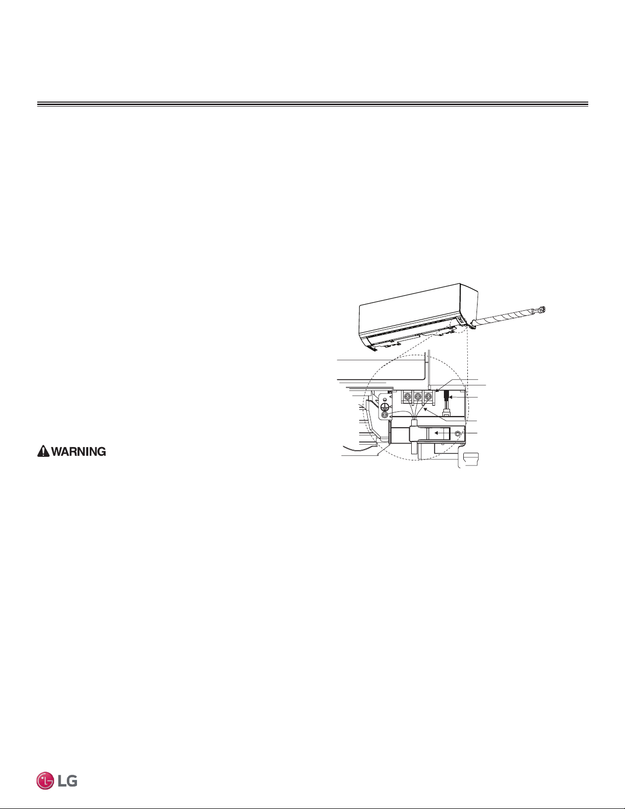
41
Installation Manual
Due to our policy of continuous product innovation, some specifications may change without notification.
©LG Electronics U.S.A., Inc., Englewood Cliffs, NJ. All rights reserved. “LG” is a registered trademark of LG Corp.
MA
X
MUL
TI
F
MUL
TI
F
IDU Electrical Connections Procedure
• Be sure that main power to the unit is completely off before
beginning this procedure. Electric shock can cause severe physical
injury or death.
• Follow all safety and warning information outlined at the beginning
and throughout this manual. Failure to do so may cause bodily injury
or death.
Note:
• Follow all safety and warning information outlined at the begin-
ning and throughout this manual. Failure to do so, may cause unit
failure.
• Some units might require you to remove the Control Cover from
the terminal block area. Most Control Covers are attached with a
phillips screw head.
• Connect the electrical cable to the indoor unit by connecting the
wires to the terminals on the control board individually according to
the outdoor unit connection. Be sure that the color of the wires at
the outdoor unit along with the terminal numbers are the same as
those for the indoor unit.
• Loose wiring may cause unit malfunction, or the terminal to overheat
and catch re. Terminal screws may become loose during transport.
Properly tighten the terminal connections during installation.
Power Wiring / Communications Cable Guidelines
• These instructions are for the IDU only. For ODU wiring, refer to the ODU installation manual.
• Conrm power source specications.
• Conrm that the electrical capacity is sufcient.
• Starting current must be maintained ±10 percent of the rated current marked on the outdoor unit name plate.
• Conrm cable thickness specications.
• It is recommended that a circuit breaker is installed, especially if conditions could become wet or moist.
• Include a disconnect in the power wiring system. Add an air gap contact separation of at least 1/8 inch in each active (phase) conductor.
• A voltage drop may cause the following problems:
1. Magnetic switch vibration, fuse breaks, or disturbance to the
normal function of an overload protection device.
2. Compressor will not receive the proper starting current.
Terminal block
Power wiring /
communications cable
Wired Remote Controlle
r
Terminal (Optional)
Cable restraint
Figure 53: Typical IDU Power and Communications
Cable Connections
ELECTRICAL WIRING
Indoor Unit Electrical Connections Guidelines
The general guidelines for connecting electrical and communication
cables are similar for all standard wall-mounted indoor units; how-
ever, the connections on the terminal block may differ. Depending
on your indoor unit, the location of the terminal block on the indoor
unit might vary from these typical images. Figure 53 shows typical
connections.
The electrical connections procedure includes wiring diagrams for
each type of standard wall-mounted indoor unit.
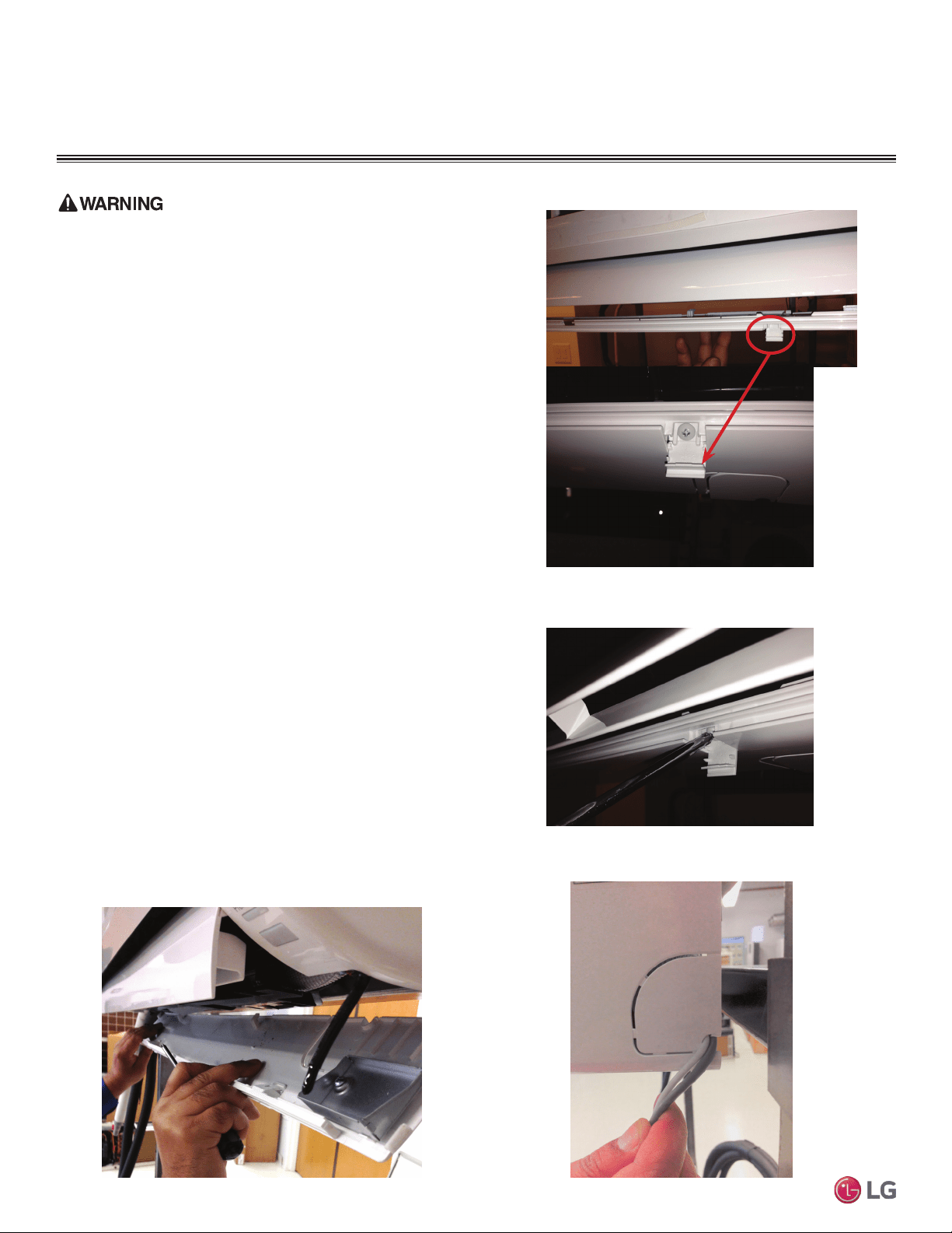
42
Multi F Standard Wall-Mounted Indoor Unit
Due to our policy of continuous product innovation, some specifications may change without notification.
©LG Electronics U.S.A., Inc., Englewood Cliffs, NJ. All rights reserved. “LG” is a registered trademark of LG Corp.
MA
X
MUL
TI
F
MUL
TI
F
ELECTRICAL WIRING
Indoor Unit Electrical Connections Procedure
Be sure there is no power input to the system before proceeding with
these connections. There is risk of electrical shock resulting in serious
bodily injury or death.
1. At the bottom panel of the indoor unit, unsnap the latches cover-
ing the phillips head screws as shown in Figure 54.
• Normally, there are three (3) screws on the panel, however, your
indoor unit model may differ.
2. Using a phillips head screwdriver, remove the screws from the
bottom panel of the indoor unit and set aside (Figure 55).
3. Remove the bottom panel (Figure 56).
• Removal is necessary to gain access to the terminal block
located at the bottom of most indoor units.
4. Route the electrical/communications wiring through the back/bot-
tom of the indoor unit (through a knockout panel, Figure 57).
5. Using a screwdriver, connect the wires as shown in Figure 58 and
Figure 59. Also refer to the appropriate wiring diagram for the IDU
(Figure 60 through Figure 63).
• Each wire should be securely attached to the terminal block.
• Ensure the green/yellow ground cable is securely connected to
the correct screw terminal.
6. When done, reattach the bottom panel to the indoor unit, being
careful to align panel using the rear tabs.
• You might need to give the panel a gentle tap with the palm of your
hand to be sure it engages at the bottom.
7. Using a phillips screwdriver, reattach the screws to the bottom
panel and secure.
8. Once screws are in place, re-snap the latches over the screws.
9. If all other piping and electrical wiring to the outdoor unit has
been completed, you can turn the system on to test.
• If you have not completed the piping connections, do not turn
power on at this time. Be sure to complete all other piping,
(along with drain hose) and wiring to the system.
Figure 54: Latch over Screws on Bottom Panel, Indoor Unit
Figure 55: Remove Screws from Bottom Panel
Figure 56: Removal (and Reattachment) of Bottom Panel
Figure 57: Indoor Unit Knockout (Communication Wires)
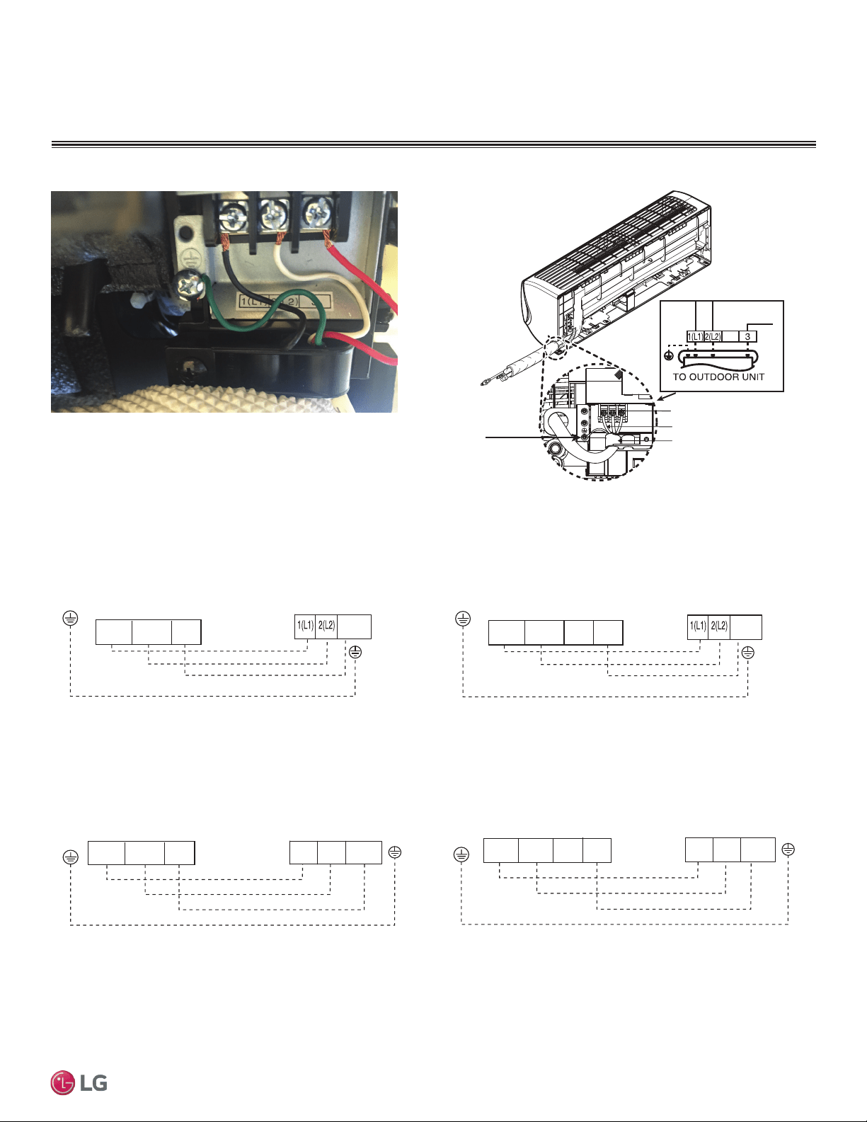
43
Installation Manual
Due to our policy of continuous product innovation, some specifications may change without notification.
©LG Electronics U.S.A., Inc., Englewood Cliffs, NJ. All rights reserved. “LG” is a registered trademark of LG Corp.
MA
X
MUL
TI
F
MUL
TI
F
ELECTRICAL WIRING
Figure 58: Typical Indoor Unit Terminal Block with Grounding Cable
Indoor Unit Electrical Connections
Terminal Block
Terminal Block
Expanded View
Grounding
Cable
Connecting Cables
Cable Restrainer
180HSV4
Figure 59: Typical Indoor Unit Terminal Block Connections
Figure 60: Indoor Unit to Outdoor Unit / Branch
Distribution Unit Terminal Connections—LMN077HVT and LMN157HVT.
Figure 61: Indoor Unit to Outdoor Unit / Branch
Distribution Unit Terminal Connections—LMN247HVT.
Figure 62: Indoor Unit to Outdoor Unit / Branch
Distribution Unit Terminal Connections—LSN090HSV4 and LSN120HSV4.
Figure 63: Indoor Unit to Outdoor Unit / Branch
Distribution Unit Terminal Connections—LSN180HSV4.
Indoor Unit Terminal Block
GND
Outdoor Unit Terminal Block or
Branch Distribution Unit Terminal Block
(Multi F MAX Systems Only)
GND
GRN / YLW
BR
BL
RD
3 or S
3(C)2(L2)1(L1)
Indoor Unit Terminal Block
1(L1 )2(L2)
GND
3
Outdoor Unit Terminal Block or
Branch Distribution Unit Terminal Block
(Multi F MAX Systems Only)
GND
GRN / YLW
BR
BL
RD
4
3 or S
Indoor Unit Terminal Block
GND
Outdoor Unit Terminal Block or
Branch Distribution Unit Terminal Block
(Multi F MAX Systems Only)
GND
GRN / YLW
BR
BL
RD
3 or S 2(L2)1(L1)
3
2(L2)
1(L1)
Indoor Unit Terminal Block
GND
Outdoor Unit Terminal Block or
Branch Distribution Unit Terminal Block
(Multi F MAX Systems Only)
GND
GRN / YLW
BR
BL
RD
3 or S2(L2)1(L1)
3
1(L1) 2(L2)
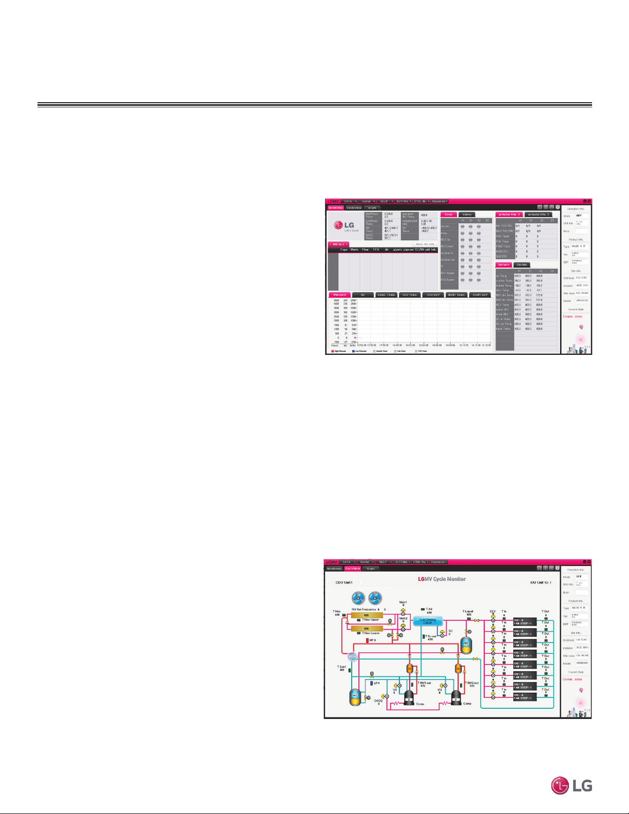
44
Multi F Standard Wall-Mounted Indoor Unit
Due to our policy of continuous product innovation, some specifications may change without notification.
©LG Electronics U.S.A., Inc., Englewood Cliffs, NJ. All rights reserved. “LG” is a registered trademark of LG Corp.
MA
X
MUL
TI
F
MUL
TI
F
ELECTRICAL WIRING
Additional screens can be accessed by tabs on the main screen.
Additional screens include the following:
1. Cycleview (Figure 65): Graphic of internal components including:
• Compressors showing actual speeds
• EEVs
• IDUs
• Temperature and pressure sensors
• Four-way reversing valve
2. Graph: Full screen graph of actual high and low pressures and high
and low pressure limits. A sliding bar enables user to go back in
time and view data.
3. Control FTN: Enables user to turn on IDUs in 1.8°F increments.
4. Useful Tab
• Unit Conversion: Converts metric values to imperial values.
5. Data
• Actual inverter compressor speed
• Target inverter compressor speed
• Actual outdoor fan speed
• Target outdoor unit fan speed
• Actual superheat
• Target superheat
• Actual subcooler circuit superheat
• Target subcooler circuit superheat
• Main EEV position
• Subcooling EEV position
• Inverter compressor current transducer
value
• Outdoor air temperature
• Actual high pressure/saturation tempera-
ture
• Actual low pressure/saturation tempera-
ture
• Suction temperature
• Inverter compressor discharge tempera-
ture
• Front outdoor coil pipe temperature
• Back outdoor coil pipe temperature
• Liquid line pipe temperature
• Subcooler inlet temperature
• Subcooler outlet temperature
• Average indoor
unit (IDU) pipe
temperature
• Inverter compres-
sor operation
indicator light
• Liquid injection
valves’ operation
indicator lights
• Hot gas bypass
valve operation
indicator light
• Four-way revers-
ing valve opera-
tion
indicator light
• Pressure graph showing actual low pres-
sure and high
pressure levels
• Error code display
• Operating mode indicator
• Target high pressure
• Target low pressure
• PCB (printed circuit board) version
• Software version
• Installer name
• Model number of IDUs
• Site name
• Total number of connected IDUs
• Communication indicators
• IDU capacity
• IDU operating mode
• IDU fan speed
• IDU EEV position
• IDU room temperature
• IDU inlet pipe temperature
• IDU outlet pipe temperature
• IDU error code
LG Monitoring View (LGMV) Diagnostic Software
LGMV software (PRCTSL1 and PRCTFE1) allows the service technician or commissioning agent to connect a computer USB port to the
outdoor unit’s main printed circuit board (PCB) using an accessory cable. The monitoring screen for LGMV allows the user to view the fol-
lowing real time data on one screen (Figure 64):
Figure 64: MV Real-time Data Screen
Figure 65: MV Cycleview
Note:
Images on these pages are examples of LGMV screenshots. Actual images
may differ depending on the version of the software and the unit installed.
Self Diagnosis Functions
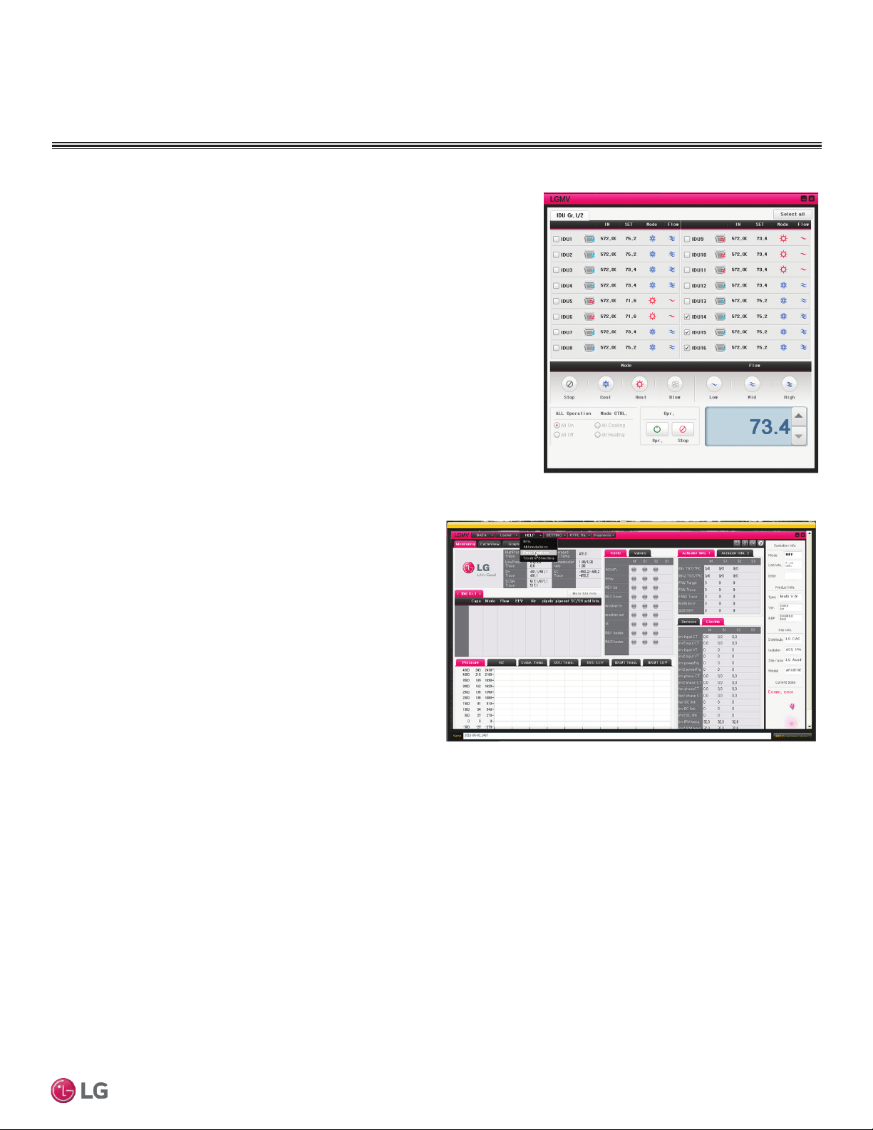
45
Installation Manual
Due to our policy of continuous product innovation, some specifications may change without notification.
©LG Electronics U.S.A., Inc., Englewood Cliffs, NJ. All rights reserved. “LG” is a registered trademark of LG Corp.
MA
X
MUL
TI
F
MUL
TI
F
ELECTRICAL WIRING
Self Diagnosis Functions
• Data Saving Start: Recording of real time data to a separate le created to be
stored on the user’s computer.
• Data Loading Start: Recorded data from a saved “.CSV” le can be loaded to
create an LGMV session.
6. Monitoring
• Electrical: The lower half of main screen is changed to show Inverter
Compressor Amps, Volts, Power Hz, Inverter control board fan Hz.
Figure 66: MV Control Indoor Units Screen
The software is available in a high version with all of the listed
features The low version has all features as the high version without
Target High Pressure and Target Low Pressure values shown on
main screen.
In lieu of connecting to the outdoor unit, there is the option to con-
nect to an IDU with the use of a USB to RS-485 connector kit. When
connected through an IDU, the user will not be able to record data.
This software can be used to both commission new systems and
troubleshoot existing systems. LGMV data can be recorded to a
“.CSV” file and emailed to an LG representative to assist with diag-
nostic evaluations.
Error Codes
LGMV software helps the service technician or commissioning agent
to troubleshoot system operation issues by displaying malfunction
codes (Figure 67). These error codes can be seen on the main
screen of the LGMV software program. For an overview of Single
Zone unit error codes, see Error Codes section. For detailed infor-
mation on how to troubleshoot individual error codes, see the Single
Zone Service Manual.
Figure 67: Error Code Screen
Recommended Minimum PC Configuration:
• CPU: Pentium
®
IV 1.6 GHz
• Main Memory: 1G
• Operating System: Windows
®
XP/Vista/7 32 bit (recommended), 64 bit
• Hard Disk: 600 MB when operating
• MS Ofce 2003, 2007 (recommended) for select reporting functions
LG Monitoring View (LGMV) Diagnostic Software and Cable - Continued
Note:
Images on these pages are examples of LGMV screenshots. Actual images
may differ depending on the version of the software and the unit installed.
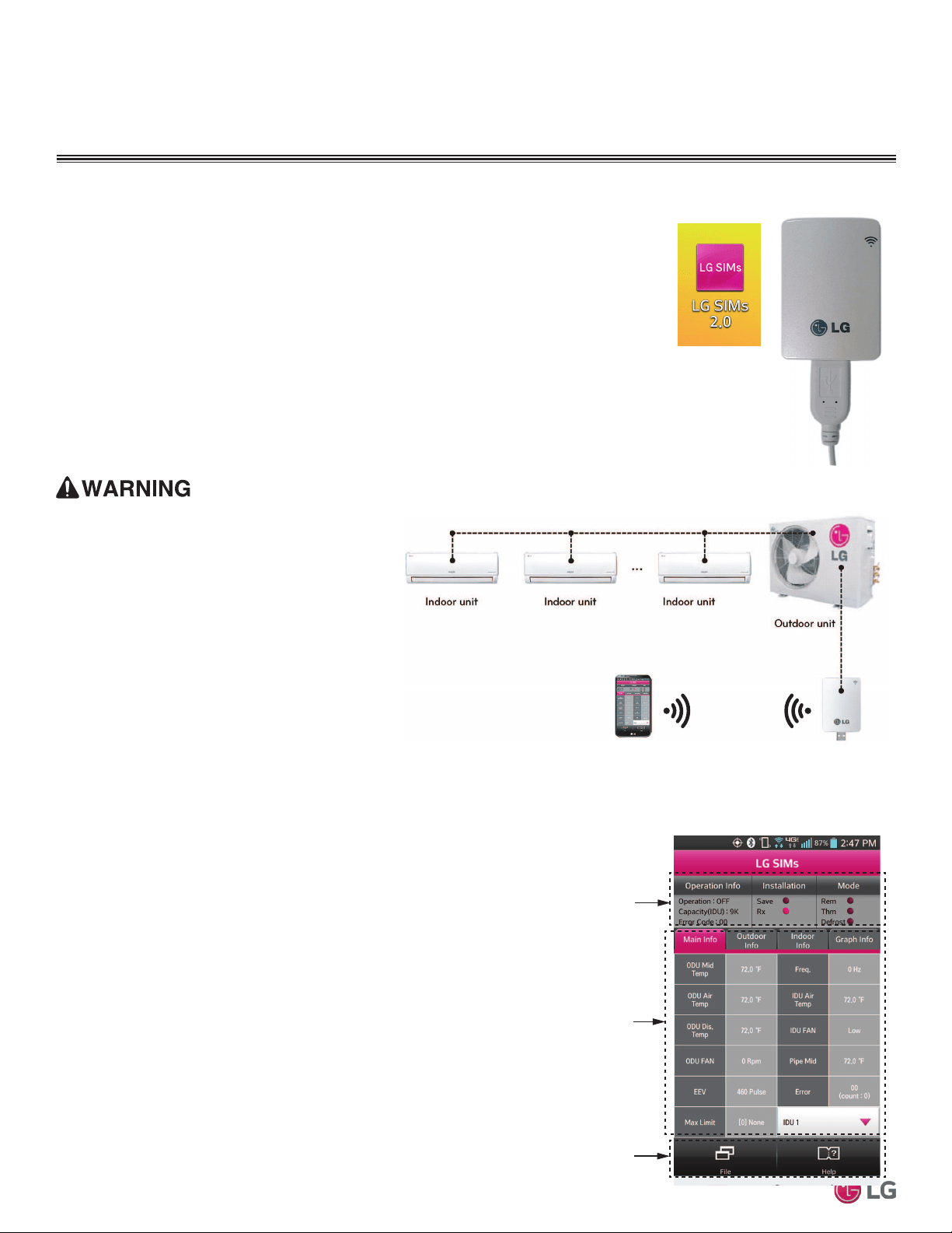
46
Multi F Standard Wall-Mounted Indoor Unit
Due to our policy of continuous product innovation, some specifications may change without notification.
©LG Electronics U.S.A., Inc., Englewood Cliffs, NJ. All rights reserved. “LG” is a registered trademark of LG Corp.
MA
X
MUL
TI
F
MUL
TI
F
ELECTRICAL WIRING
LG SIMS - Self Diagnosis Functions
LG SIMs
WLAN Module
LG SIMs App
on Smart Phone
The SIMs WLAN module and the smart phone app together provide monitoring and troubleshooting
capability for LG Duct Free Systems. SIMs functions only with LG Duct Free products (Figure 68).
SIMs can display and graph operational data for the air conditioner system including the indoor unit
and the outdoor unit. SIMs also displays error codes and a troubleshooting guide. A full copy of
the LG SIMs Smart Inverter Monitoring System User’s Manual is available on the www.lghvac.com
website.
To use SIMs you must be a trained HVAC service technician familiar with variable refrigerant
flow (VRF) systems in general and with LG’s Duct Free System products. You should under-
stand the inverter air conditioning operation cycle, the meaning of the data displayed by SIMs,
and how to use the data to troubleshoot the system.
Figure 69 shows a typical Multi F configuration used with the SIMs module and app.
Note:
• The Duct Free System air conditioning system must run for
at least 15–20 minutes before data collected by SIMs 2.0 is
valid for troubleshooting.
• You must have the free SIMs app correctly installed on your
smart phone before using SIMs.
• Some ODUs have an LGMV extension cable accessed by
removing the side handle cover. If the ODU does not have
this extension cable, access the LGMV connector by remov-
ing the top cover of the ODU.
High voltages capable of causing death are used in
this equipment. Outdoor unit power remains connected
during this procedure. Take extreme caution not to
touch electrical components or connections. Failure to
observe this warning can result in death or severe injury.
Figure 68: LG SIMs App and WLAN Module
Figure 69: SIMs WLAN Module to a Typical Multi F System
Figure 70: SIMs App Main Info Screen
The main screen (Figure 70) is the first screen displayed after wireless
connection is established. Tap the Main Info tab to display current read-
ings regarding your indoor and outdoor unit(s). The Operational Info area
of the screen will show active functions or modes by illuminating the light
to the right of the function.
Additional Help information can be accessed by tapping the Help Menu
buttons at the bottom of this screen.
Operational
Information
AC Cycle
Information on
Main Info Tab
Help Menu
(File is Factory Use Only)
SIMs App Main Info Screen
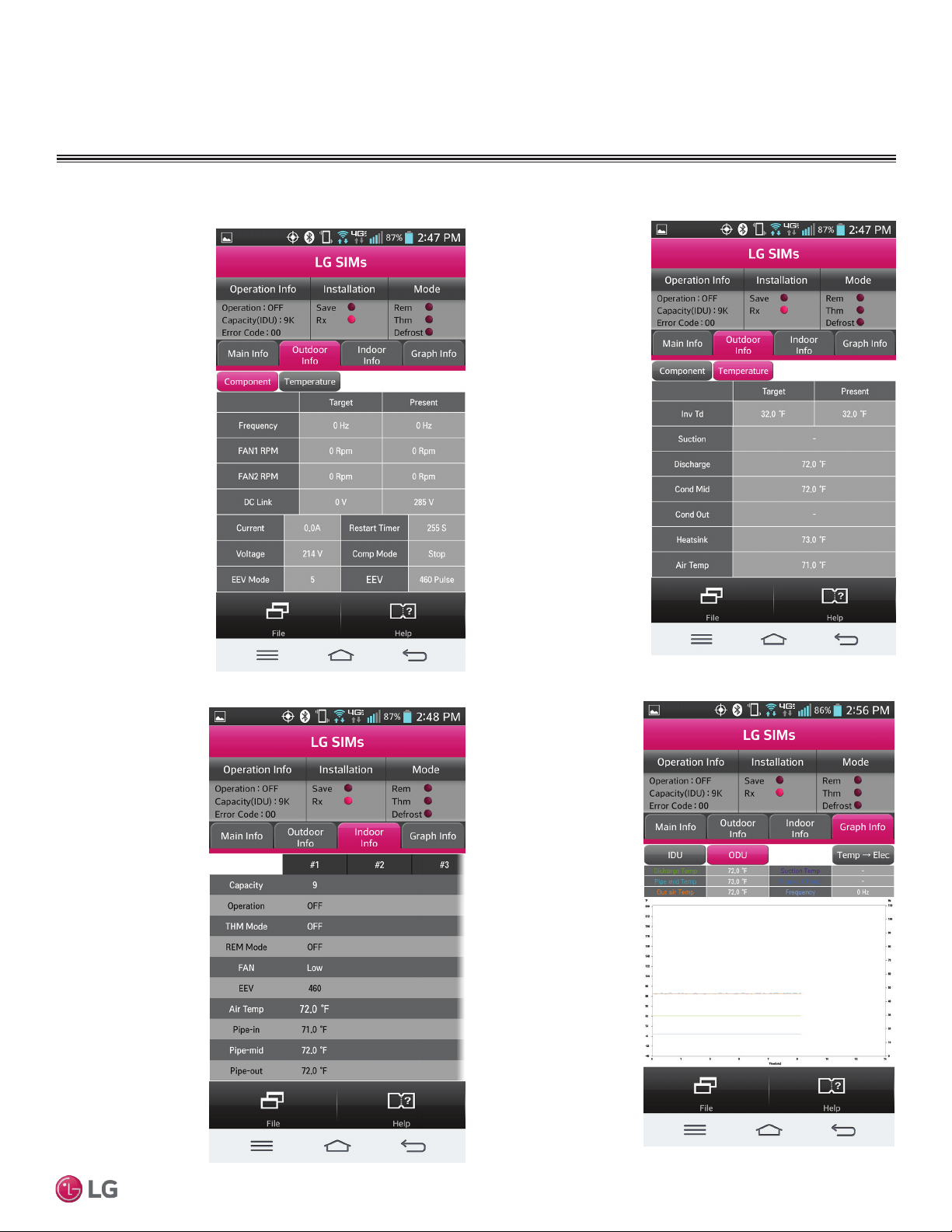
47
Installation Manual
Due to our policy of continuous product innovation, some specifications may change without notification.
©LG Electronics U.S.A., Inc., Englewood Cliffs, NJ. All rights reserved. “LG” is a registered trademark of LG Corp.
MA
X
MUL
TI
F
MUL
TI
F
ELECTRICAL WIRING
LG SIMS - Self Diagnosis Functions
SIMs App Screens
Outdoor Info/
Component Screen
Displays the following
information:
• Frequency
• FAN1 RPM
• FAN2 RPM
• DC Link
• Current
• Voltage
• EEV Mode
• Restart Timer
• Comp Mode
• EEV
Indoor Info Tab
Displays the following
information:
• Frequency
• Operation
• THM Mode
• REM Mode
• FAN
• EEV
• Air Temp
• Pipe-in
• Pipe-mid
• Pipe-out
Graph Info Tab
This tab, has three sub
sections:
• IDU - Indoor Unit
Temperature graph.
Displays IDU
information in graph
format. Information
displayed is for the
IDU # selected on
the Main screen.
• ODU - Outdoor Unit
Temperature and
Frequency graph.
Displays ODU
information in graph
format.
• ODU Electric
- Outdoor Unit
Electric data graph
is displayed.
Outdoor Info/
Temperature Screen
Displays the following
information:
• Inv TD
• Suction
• Discharge
• Cond Mid
• Cond Out
• Heatsink
• Air Temp
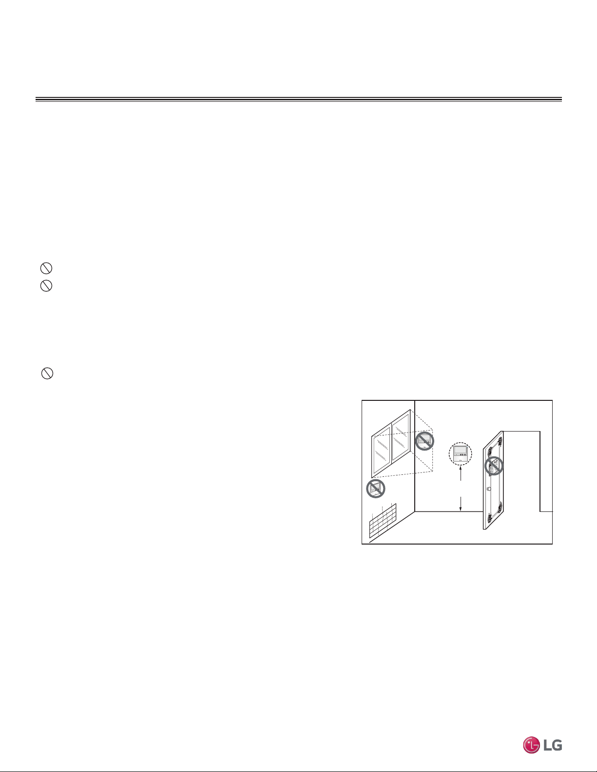
48
Multi F Standard Wall-Mounted Indoor Unit
Due to our policy of continuous product innovation, some specifications may change without notification.
©LG Electronics U.S.A., Inc., Englewood Cliffs, NJ. All rights reserved. “LG” is a registered trademark of LG Corp.
MA
X
MUL
TI
F
MUL
TI
F
Wall-Mounted Sensor Installation
Proper indoor unit operation depends on the location of the room sensor. A good location will protect the zone controller from direct sunlight
and external local sources of water vapor, and heated or cooled air. If no mounting height was specified by the building designer, place the
handy box approximately fifty-five (55) inches above the finished floor.
• It may be necessary to use a handy box that is sized in metric units, depending on the controller model. Check with your LG representative
to verify which size of handy box is needed for the zone controller in question.
• Use only LG-supplied communications cable. Using eld-supplied cable may result in communications problems between the zone control-
ler and the indoor unit.
• Maintain the minimum distance required between the communications cable and power wiring. The minimum required space between
the two is dependent on the voltage of the power wiring. Refer to the appropriate Multi V Outdoor Unit Engineering Manual for minimum
distance specications.
Do not route power wiring and communications cables in the same conduit.
Do not cut the quick-connect plugs off or adjust the length of the cable. Keep the communications cable away from high voltage wires
and electromagnetic field (EMF) producing equipment.
ELECTRICAL WIRING
Wall-Mounted Controller Installation
Since the room temperature sensor is inside the remote controller, the remote controller should be installed in a place away from direct sun-
light, high humidity and direct supply of hot or cold air to maintain proper space temperature. Install the remote controller about 5 ft above
the floor in an area with good air circulation and an average temperature.
Do not install the remote controller where it can be affected by the following:
• Drafts or dead spots behind doors and in corners
• Hot or cold air from ducts
• Radiant heat from sun or appliances
• Concealed pipes and chimneys
• Uncontrolled areas such as an outside wall behind the remote controller
This remote controller is equipped with a seven segment LED display. For proper
display of the remote controller LED’s, the remote controller should be installed
properly as shown below. The standard height is 4 - 5 ft from floor level.
1. Pull communications cable between the zone controller handy box (if used) and
the indoor unit. The wall-mounted zone controller comes with a thirty (33) foot
length of cable.
2. Store a minimal amount of cable in the handy box. Any additional cable should be
coiled and stored near the indoor unit control panel.
3. If additional cable length is needed, order a thirty (33) foot LG Wired Remote
Group Control Extension cable (Model No. PZCWRC1).
4. If the cable between the zone controller and the indoor unit is too long, do not cut the cable and shorten. Coil any spare communications
cable, tie-wrap it, and leave it next to the indoor unit location.
5ft
no
no
no
yes
Remote Controller
TEMP
Remote Controller
TEMP
Remote Controller
TEMP
Figure 71: Wired Remote Controller Installation
Optional Wall-Mounted Sensor and Controller
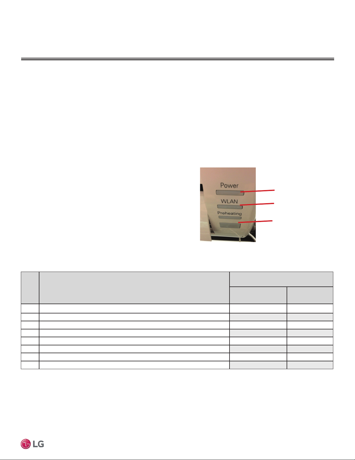
49
Installation Manual
Due to our policy of continuous product innovation, some specifications may change without notification.
©LG Electronics U.S.A., Inc., Englewood Cliffs, NJ. All rights reserved. “LG” is a registered trademark of LG Corp.
MA
X
MUL
TI
F
MUL
TI
F
Troubleshooting Using Error Codes
Refer to Table 27 for information on error codes generated from
the indoor and outdoor units. These codes are the most common
that will manifest through these units. Your particular model duct
free system might generate additional codes not listed here. Please
contact LG Support if you see these types of errors and a simple
power down and boot up has not corrected the issue. You should not
attempt to fix the system yourself.
Error Codes
• Refer to the gures below for your particular indoor unit’s LED
conguration.
• Indicate different types of unit failures, assists in self-diagnosis
and to track the frequency of occurrence.
• Error codes are shown on the LEDs of indoor units, wired
remote controller, the Single Zone unit control board, and LG
Monitoring View (LGMV) Diagnostic Software.
• If two or more errors occur simultaneously, the lower error code
number is displayed rst.
• After error is resolved, the error code does not display.
Error Codes
Decoding the Error Display
The first and second number on the LED indicates error number.
Example: 21 = LED1 (Green light) 2x blink, LED2 (Red light) 1x blink
Error Code Nomenclature Definitions
• MICOM: Non-volatile memory chip where unit setup information
is stored.
• EPROM: Non-volatile memory chip where device identication,
size, and factory dened default component operating param-
eters are stored.
LED 1
(UNITS PLACE)
LED 2
(TENS PLACE)
Receiver
Figure 72: IDU LS-HSV4 Models
Error
Code
Description
No. of Times Indoor Unit
LEDs Blink
LED1
(Plasma LED)
LED2
(Power LED)
1 Indoor unit room temperature sensor error
1X -
2 Indoor unit inlet pipe sensor error 2X -
4 Float switch error (optional) 4X -
5 Communication error between indoor unit and outdoor units - 5X
6 Indoor unit outlet pipe sensor error 6X -
9 Indoor unit EPROM error 9X -
10 Indoor unit BLDC motor fan lock - 1X
12 Indoor unit middle pipe sensor error 2X 1X
Table 27: Multi Zone Wall-Mounted Indoor Unit Error Codes
TROUBLESHOOTING
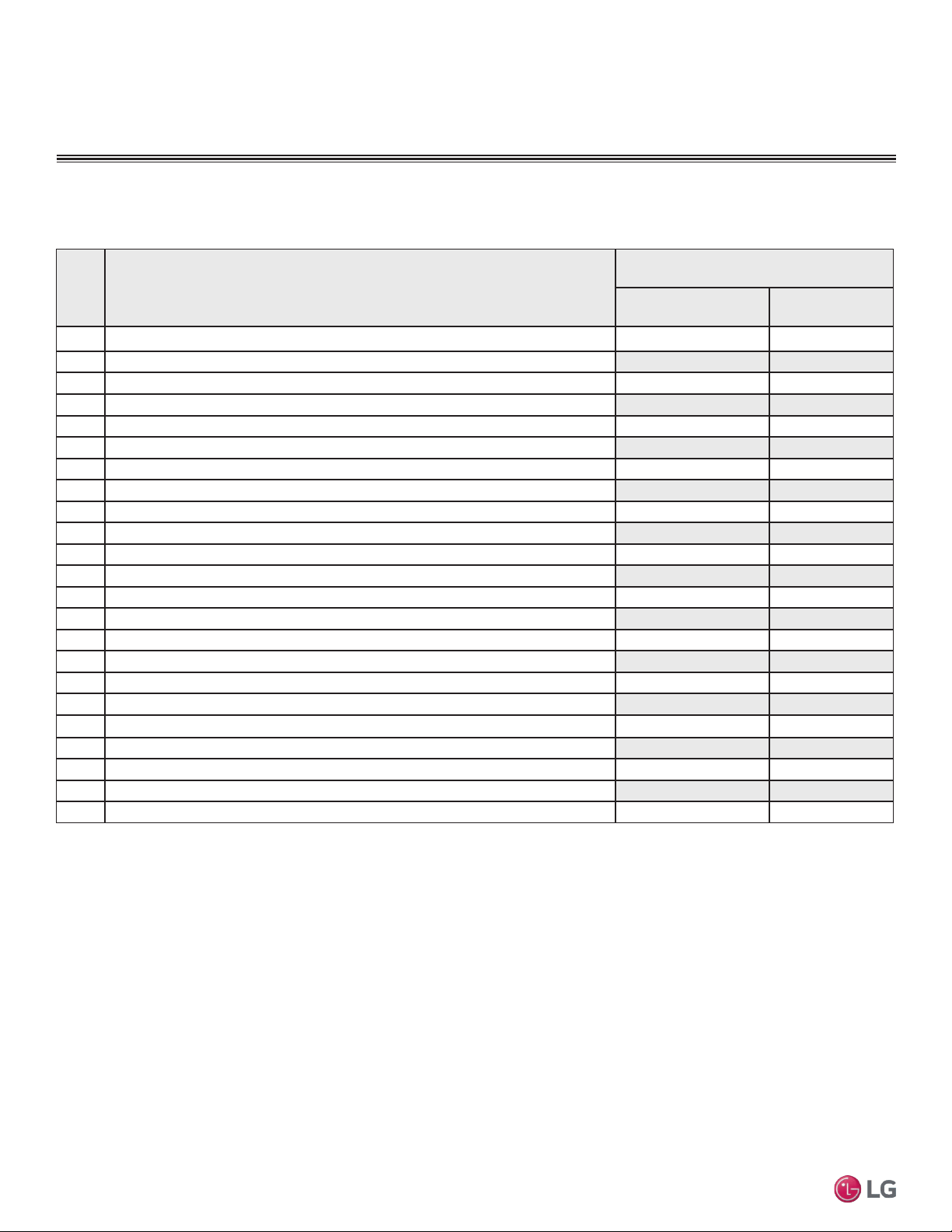
50
Multi F Standard Wall-Mounted Indoor Unit
Due to our policy of continuous product innovation, some specifications may change without notification.
©LG Electronics U.S.A., Inc., Englewood Cliffs, NJ. All rights reserved. “LG” is a registered trademark of LG Corp.
MA
X
MUL
TI
F
MUL
TI
F
Error Codes
Error
Code
Description
No. of Times Indoor Unit
LEDs Blink
LED1
(Plasma LED)
LED2
(Power LED)
21 DC Peak (IPM Fault); Compressor DC voltage was too high
2X 1X
22 Current Transformer2 (CT2) error; Alternating current (AC) input too high 2X 2X
23 DC Link Low Volt 2X 3X
25 AC Low/High Volt 2X 5X
26 DC Comp Position Error (not providing rotation), Locking 2X 6X
27 PSC Fault; Current to inverter compressor between AC and DC converter circuit too high 2X 7X
28 Inverter compressor DC voltage is too high 2X 8X
29 Inverter compressor amperage is too high 2X 9X
31 Current-to-current transformer (CT) thermistor is too low 3X 1X
32 Inverter Compressor Discharge Pipe (D-Pipe) Overheat 3X 2X
40 CT Sensor Error; Thermistor is disconnected or shorted out 4X -
41 D-Pipe Sensor INV is disconnected or shorted out 4X 1X
44 Outdoor Air Sensor is disconnected or shorted out 4X 4X
45 Middle thermistor of outdoor unit condenser coil is disconnected or shorted out 4X 5X
46 Outdoor unit suction line thermistor is disconnected or shorted out 4X 6X
48 Outdoor unit coil outlet (liquid line) thermistor is disconnected or shorted out 4X 8X
53 Communication failure from outdoor unit to indoor unit 5X 3X
60 Outdoor unit printed circuit board (PCB) EPROM check sum error 6X -
61 Outdoor unit condenser coil temperature is too high
6X 1X
62 Outdoor unit inverter compressor PCB heat sink temperature is too high 6X 2X
63 Condenser coil pipe thermistor temperature is too low 6X 3X
65 Heat sink thermistor has disconnected or has shorted out 6X 5X
67 Outdoor brushless direct current (BLDC) fan motor lock error 6X 7X
Troubleshooting Using Error Codes - Continued
Refer to Service Manuals posted on www.lghvac.com for a full description of all error codes and workarounds.
Table 22: Multi Zone Wall-Mounted Indoor Unit Error Codes - Continued
TROUBLESHOOTING
51
Installation Manual
Due to our policy of continuous product innovation, some specifications may change without notification.
©LG Electronics U.S.A., Inc., Englewood Cliffs, NJ. All rights reserved. “LG” is a registered trademark of LG Corp.
MA
X
MUL
TI
F
MUL
TI
F
Amount of
Factory-Charged
Refrigerant per
Outdoor Unit
Amount of
Additional Re-
frigerant Trim
Charge
Refrigerant Concentration Limit (RCL) Calculations
To calculate total refrigerant amount per system:
Cautions for Refrigerant Leaks
ASHRAE Standards 15-2010 and 34-2010 offer guidelines that address refrigerant safety and the maximum allowable concentration of refrig-
erant in an occupied space. Refrigerant will dissipate into the atmosphere, but a certain volume of air is required for this to occur safely. For
R410A refrigerant, the maximum allowable concentration is 0.026 lbs./ft
3
per 1,000 ft
3
of air in an occupied space. Buildings with twenty-four
(24) hour occupancy allow half of that concentration.
1
ASHRAE Standards 15 and 34 assume that if a system develops a leak, its entire refrigerant charge will dump into the area where the leak
occurs. To meet ASHRAE Standards 15 and 34, calculate the refrigerant concentration that may occur in the smallest room volume on
the system, and compare the results to the maximum allowable concentration number (see below for information on how to calculate the
refrigerant concentration).
1
Also consult state and local codes in regards to refrigerant safety.
Verify the maximum refrigerant concentration level in the space where the indoor unit will be mounted meets the concentration limit for the
application. If the refrigerant leaks and safety limits are exceeded, it could result in personal injuries or death from oxygen depletion.
1
American Society of Heating, Refrigeration and Air Conditioning Engi-
neers, Inc. (ASHRAE). Atlanta, GA. ASHRAE, Inc. Information about
ASHRAE Standard 15-2010 / 34-2010 and addenda current as of the
date of this publication.
Take appropriate actions at the end of HVAC equipment life to recover, recycle, reclaim or destroy R410A refrigerant according to applicable
US EPA rules.
Total System
Refrigerant
Charge
+ =
To calculate the potential refrigerant concentration level (RCL):
1. Measure the occupied space dimensions (in feet).
2. Calculate the cubic foot volume of air in the smallest occupied
space. (To obtain a detailed overview of the RCL, perform the
same calculations to the second smallest zone, the third small-
est zone until the RCL is obtained for all zones. Also, pay special
attention to areas such as basements, etc., where refrigerant
cannot dissipate easily.)
3. Divide the refrigerant charge of the Single Zone system serving
the area in pounds by the results of step 1.
4. If the calculation indicates that the potential refrigerant concen-
tration level is higher than the allowed RCL, increase the cubic
volume of the smallest occupied space or modify the piping
system design.
5. The allowable RCL limit for most applications must be equal to
or less than 0.026 lbs./ft
3
. In special occupied spaces, however,
such as hospitals and nursing homes where occupants may have
limited mobility, the allowable RCL limit is cut in half. See ASHRAE
Standard 34-2007 and local codes for detailed information.
1
RCL (lbs./ft
3
) =
Total System Refrigerant Charge (lbs.)
Volume of Smallest Occupied Space (ft
3
)
Refrigerant Leaks
CAUTIONS FOR REFRIGERANT LEAKS
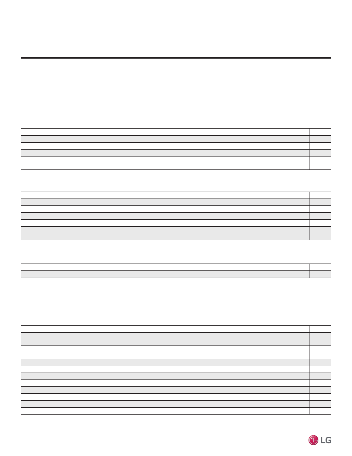
52
Multi F Standard Wall-Mounted Indoor Unit
Due to our policy of continuous product innovation, some specifications may change without notification.
©LG Electronics U.S.A., Inc., Englewood Cliffs, NJ. All rights reserved. “LG” is a registered trademark of LG Corp.
MA
X
MUL
TI
F
MUL
TI
F
System ID No.: _________________________________________________ Indoor Unit ID.: ____________________________________
Checked by: __________________________________ Date:__________________ Signature: ___________________________________
PAGE 1 of 2
INSTALLATION CHECKLIST
Major Component Rough-In
Description Check
Single Zone unit was connected properly per local code and the product installation procedures.
All literature and bagged accessories have been removed from the fan discharge.
Indoor unit was installed, properly supported, and located indoors in a non-corrosive environment.
Single Zone unit’s gravity condensate drain line was connected and routed where it properly drains away or, if installed in a
mechanical room, was connected and properly routed to a drain terminal.
Piping and Insulation
Description Check
Copper
Over 5/8 inches—Rigid ACR only.
5/8 inches and under—Can use soft ACR.
15% silver brazing material only.
All refrigerant pipes and valves were insulated separately. Insulation butts up against the walls of the indoor units. No gaps or
cracks. Insulation was not compressed at clamps and hangers.
Brazing Practices
Description Check
Medical grade (there are 4 available) dry nitrogen for purging during brazing was used (constant 3 psi while brazing).
Installation
(For more information on any procedure, refer to the detail provided in the installation section.)
Refrigerant Piping
Description Check
All pipe materials were properly stored, capped, and clean. All burrs were removed after cutting and pipe ends were reamed
before brazing.
During refrigerant pipe installation, for each segment of pipe, a record was made of the pipe length (including expansion loops,
offsets, double-back sections), and sizes, as well as the quantity and type of elbows used.
All long runs of straight pipe were provided with expansion loops.
A torque wrench and backup wrench were used to tighten all flare connections.
The back side of all flares were lubricated with a small drop of PVE refrigeration oil before tightening flare fittings.
Ensure all field made flares are 45°. Use factory-supplied flare nuts only.
Pipe segments were properly supported and all wall penetrations were sleeved.
Pipe insulation was not compressed at any point.
No oil traps, solenoid valves, sight glasses, filter driers, or any other unauthorized refrigerant specialties were present.
Best practice including a minimum of 20″ of straight pipe was installed between each elbow.
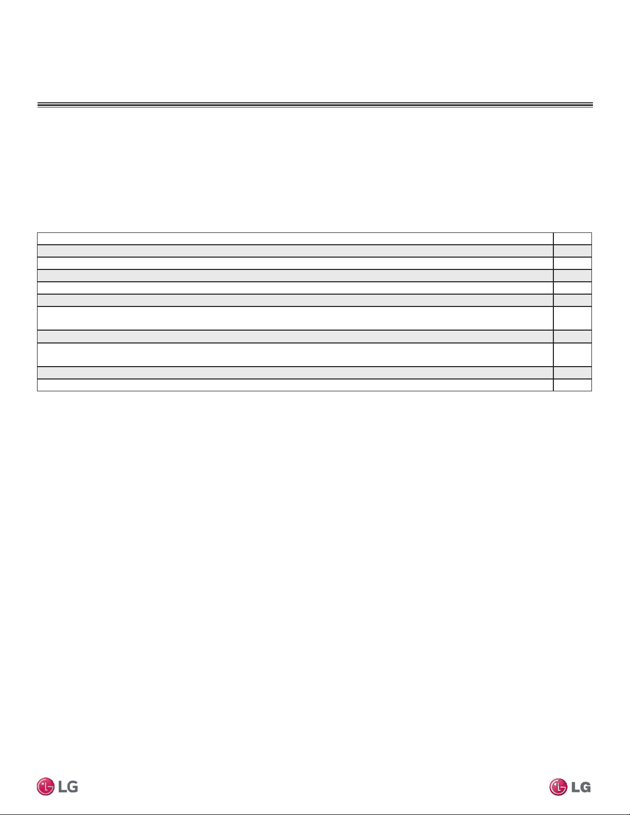
53
Installation Manual
Due to our policy of continuous product innovation, some specifications may change without notification.
©LG Electronics U.S.A., Inc., Englewood Cliffs, NJ. All rights reserved. “LG” is a registered trademark of LG Corp.
MA
X
MUL
TI
F
MUL
TI
F
53
INSTALLATION CHECKLIST
Condensate Pump / Drain Installation
Power Wire and Communications Cables
Description Check
Power wiring was connected to a single phase 208-230V source.
Ground wire was installed and properly terminated at the unit.
The power supplied was clean with voltage fluctuations within specifications. (±10% of nameplate).
Power wiring to the Single Zone outdoor unit was installed per all local electrical code requirements.
Power wiring to the indoor unit was installed per all local electrical code requirements.
LG-supplied cable was used between the indoor unit and its zone controller. No cables were spliced and no wire caps are
present.
Communication type RS-485–BUS type.
All communications cables were a minimum of 18-AWG, four (4) conductor, shielded, and stranded, with insulation material per
local code. Cable segment shields were tied together.
Used appropriate crimping tool to attach ring or spade terminals at all power wiring and control cable terminations.
All power and control wires were properly separated using the recommended distance provided in the product installation manual.
For further technical materials such as submittals, engineering
manuals, service manuals, and catalogs, visit www.lghvac.com.
System ID No.: _________________________________________________ Indoor Unit ID.: ____________________________________
Checked by: __________________________________ Date:__________________ Signature: ___________________________________
PAGE 2 of 2

54
Multi F Standard Wall-Mounted Indoor Unit
Due to our policy of continuous product innovation, some specifications may change without notification.
©LG Electronics U.S.A., Inc., Englewood Cliffs, NJ. All rights reserved. “LG” is a registered trademark of LG Corp.
MA
X
MUL
TI
F
MUL
TI
F

55
Installation Manual
Due to our policy of continuous product innovation, some specifications may change without notification.
©LG Electronics U.S.A., Inc., Englewood Cliffs, NJ. All rights reserved. “LG” is a registered trademark of LG Corp.
MA
X
MUL
TI
F
MUL
TI
F
Who to call for assistance
Freight Damage and Unit Replacements Your LG Manufacturer Representative
Missing Parts Your LG Manufacturer Representative
Freight Damage and Unit Replacements Your LG Manufacturer Representative
Received Wrong Indoor Unit Model Your LG Manufacturer Representative
Installation, Startup, and Commissioning Technical Assistance 1-888-865-3026
For warranty information, visit www.lghvac.com.

IM-Multi-F_StdWallMount-03-15
Original Issue
LG Electronics
Commercial Air Conditioning Division
11405 Old Roswell Road
Alpharetta, Georgia 30009
www.lghvac.com
LG Customer Information Center, Commercial Products
1-888-865-3026 USA
Follow the prompts for commercial A/C products and parts.
20001747 ISO 9001: 2008
LG ELECTRONICS INC.