Loading ...
Loading ...
Loading ...
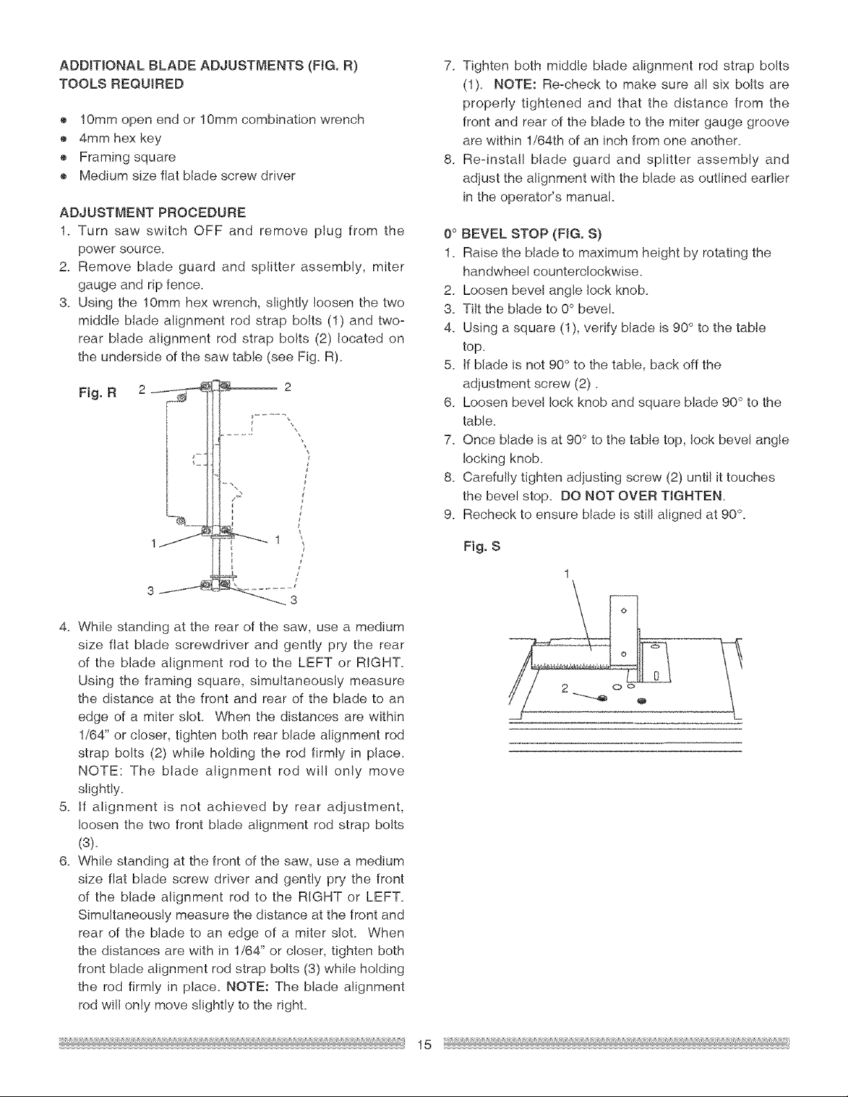
ADDiTiONALBLADEADJUSTMENTS(FIG.R)
TOOLSREQUIRED
o 10mmopenendor10ramcombinationwrench
® 4ramhexkey
o Framingsquare
o Mediumsizeflatbladescrewdriver
ADJUSTMENTPROCEDURE
1. Turn saw switch OFF and remove plug from the
power source.
2. Remove blade guard and splitter assembly, miter
gauge and rip fence.
3. Using the 10ram hex wrench, slightly loosen the two
middle blade alignment rod strap bolts (1) and two-
rear blade alignment rod strap bolts (2) located on
the underside of the saw table (see Fig. R).
4. While standing at the rear of the saw, use a medium
size flat blade screwdriver and gently pry the rear
of the blade alignment rod to the LEFT or RIGHT.
Using the framing square, simultaneously measure
the distance at the front and rear of the blade to an
edge of a miter slot. When the distances are within
1/64" or closer, tighten both rear blade alignment rod
strap bolts (2) while holding the rod firmly in place.
NOTE: The blade alignment rod will only move
slightly.
5. If alignment is not achieved by rear adjustment,
loosen the two front blade alignment rod strap bolts
(3).
6_ While standing at the front of the saw, use a medium
size flat blade screw driver and gently pry the front
of the blade alignment rod to the RIGHT or LEFT.
Simultaneously measure the distance at the front and
rear of the blade to an edge of a miter slot. When
the distances are with in 1/64" or closer, tighten both
front blade alignment rod strap bolts (3) while holding
the rod firmly in place. NOTE: The blade alignment
rod will only move slightly to the righL
7. Tighten both middle blade alignment rod strap bolts
(1). NOTE: Re-check to make sure all six bolts are
properly tightened and that the distance from the
front and rear of the blade to the miter gauge groove
are within 1/64th of an inch from one another.
8_ Re-install blade guard and splitter assembly and
adjust the alignment with the blade as outlined earlier
in the operator's manual.
0° BEVEL STOP (FIG. S)
1. Raise the blade to maximum height by rotating the
handwheel counterclockwise.
2. Loosen bevel angle lock knob.
3. Tilt the blade to 0° bevel.
4. Using a square (1), verify blade is 90 ° to the table
top.
5. If blade is not 90 ° to the table, back off the
adjustment screw (2)
6. Loosen bevel lock knob and square blade 90 ° to the
table.
7. Once blade is at 90° to the table top, lock bevel angle
locking knob.
8. Carefully tighten adjusting screw (2) until it touches
the beve! stop. DO NOT OVER TIGHTEN.
9_ Recheck to ensure blade is stilI aligned at 90%
Fig. S
15
Loading ...
Loading ...
Loading ...