Loading ...
Loading ...
Loading ...
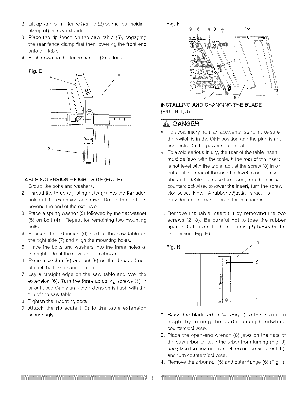
2. Liftupwardon ripfencehandle(2)sothe rearholding
clamp(4)isfullyextended.
3. Placethe rip fenceon the sawtable(5),engaging
therearfenceclampfirstthenloweringthefrontend
ontothetable.
4. Pushdownonthefencehandle(2)tolock.
Fig.E
2 _ ......
TABLE EXTENSION - RIGHT SIDE (FIG. F)
1. Group like bolts and washers.
2. Thread the three adjusting bolts (1) into the threaded
holes of the extension as shown. Do not thread bolts
beyond the end of the extension.
3. Place a spring washer (3) followed by the flat washer
(5) on bolt (4). Repeat for remaining two mounting
bolts.
4. Position the extension (6) next to the saw table on
the right side (7) and align the mounting holes.
5. Place the bolts and washers into the three holes at
the right side of the saw table as shown.
6. Place a washer (8) and nut (9) on the threaded end
of each bolt, and hand tighten.
7. Lay a straight edge on the saw table and over the
extension (6). Turn the three adjusting screws (1) in
or out accordingly until the extension is flush with the
top of the saw table.
8. Tighten the mounting bolts.
9. Attach the rip scale (10) to the table extension
accordingly.
Fig. F
9 8 5 3 4 10
7 6
INSTALLING AND CHANGING THE BLADE
(FIG. H, t, J)
[_ DANGER]
o To avoid injury from an accidental start, make sure
the switch is in the OFF position and the plug is not
connected to the power source outlet.
® To avoid serious injury, the rear of the table insert
must be level with the table. If the rear of the insert
is not level with the table, adjust the screw (3) in or
out until the rear of the insert is level to or slightly
above the table. To raise the insert, turn the screw
counterclockwise, to lower the insert, turn the screw
clockwise. Note: A rubber adjusting spacer is
provided under rear of insert for this purpose.
1.
Remove the table insert (1) by removing the two
screws (2, 3). Be careful not to lose the rubber
spacer that is on the back screw (3) beneath the
table insert (Fig. H).
1
Fig.H
l 3
2
2. Raise the blade arbor (4) (Fig. I) to the maximum
height by turning the btade raising handwhee!
counterclockwise.
3. Place the open-end wrench (8) jaws on the flats of
the saw arbor to keep the arbor from turning (Fig. J)
and place the box-end wrench (9) on the arbor nut (5),
and turn counterclockwise.
4. Remove the arbor nut (5) and outer flange (6) (Fig. I).
11
Loading ...
Loading ...
Loading ...