Loading ...
Loading ...
Loading ...
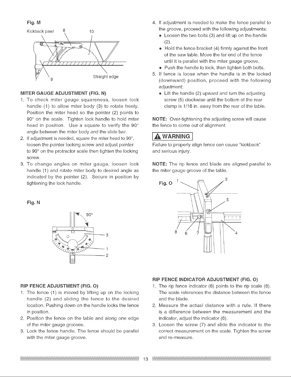
10
Straight edge
MITER GAUGE ADJUSTMENT (FIG+ N)
1+ To check miter gauge squareness, loosen lock
handle (1) to allow miter body (3) to rotate freely+
Position the miter head so the po+nter (2) points to
90° on the scale+ Tighten lock handle to hold miter
head +n position+ Use a square to verify the 90 °
angle between the miter body and the slide bar+
2+ Hfadjustment is needed, square the miter head to 90 °,
loosen the pointer locking screw and adjust pointer
to 90 ° on the protractor scale then tighten the locking
screw.
3+ To change angles on miter gauge, loosen lock
handle (1) and rotate miter body to desired angle as
indicated by the pointer (2)+ Secure in position by
tightening the lock hand+e+
4+ Jfadjustment is needed to make the fence parallel to
the groove, proceed with the following adjustments:
® Loosen the two bolts (3) and lift up on the handle
(2)+
+ Hold the fence bracket (4) firmly against the front
of the saw table+ Move the far end of the fence
until it is parallel with the m+tergauge groove.
+ Push the handle to lock, then tighten both bolts+
5+ if fence is loose when the handle is in the locked
(downward) position, proceed with the following
adjustment:
+ Lift the handle (2) upward and turn the adjusting
screw (5) clockwise until the bottom of the rear
clamp is 1/16 in+away from the rear of the table+
NOTE: Over-tightening the adjusting screw will cause
the fence to come out of alignment+
[a,WARN+NG]
Fai+ure to proper+y a++gnfence can cause "kickback"
and serious +njury+
NOTE: The rip fence and blade are aligned parallel to
the miter gauge groove of the table.
1 3
Fig. 0
Fig. N
8 6 7
RiP FENCE ADJUSTMENT (FIG. O)
1. The fence (1) is moved by lifting up on the locking
handle (2) and sliding the fence to the desired
!ocation+ Pushing down on the handle locks the fence
in position+
2+ Position the fence on the table and along one edge
of the miter gauge grooves.
3+ Lock the fence hand+e+The fence should be parallel
with the miter gauge groove+
RIP FENCE iNDiCATOR ADJUSTMENT (FIG+ O)
1+ The rip fence indicator (6) points to the rip scale (8)+
The scale references the distance between the fence
and the blade+
2+ Measure the actual distance with a rule+ if there
is a difference between the measurement and the
indicator, adjust the indicator (6)+
3. Loosen the screw (7) and slide the indicator to the
correct measurement on the scale. Tighten the screw
and re-measure+
13
Loading ...
Loading ...
Loading ...