Loading ...
Loading ...
Loading ...
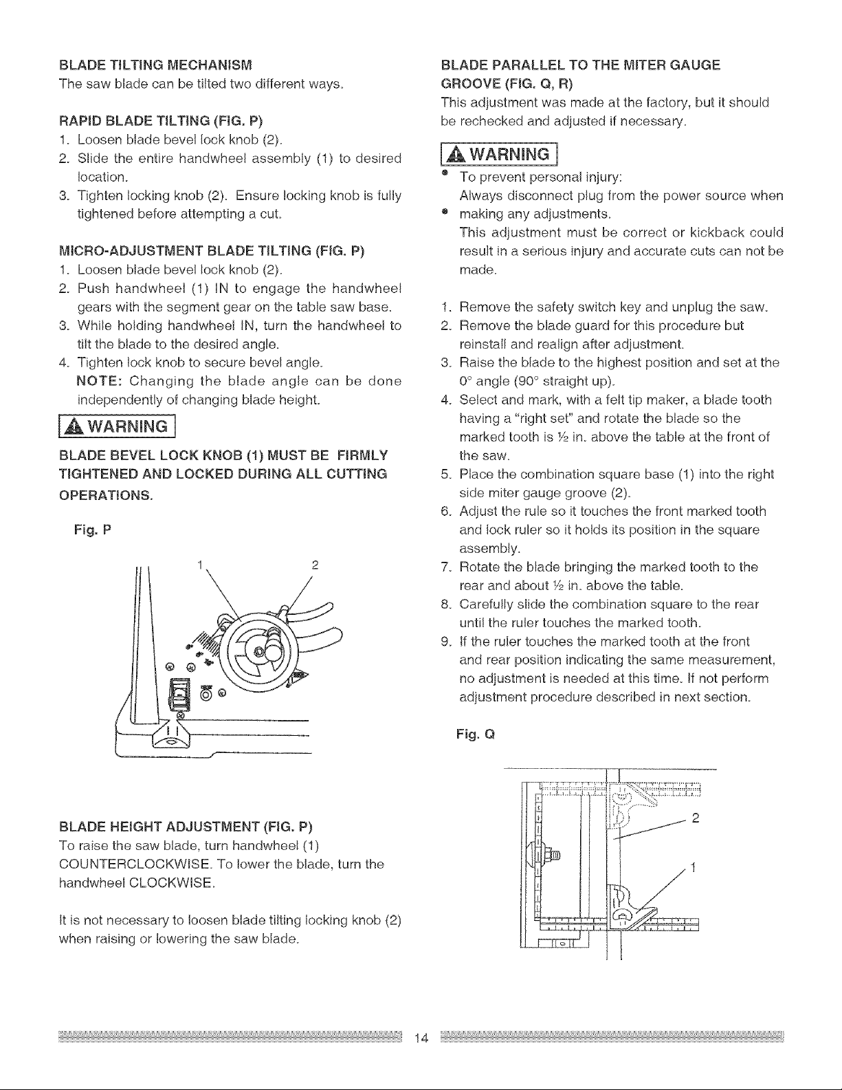
BLADETtLTJNGMECHANISM
Thesawbladecanbetiltedtwodifferentways.
RAPIDBLADETtLTING(FIG.P)
1. Loosenbladebevellockknob(2).
2. Slidetheentirehandwheelassembly(1) to desired
!ocation_
3. Tightenlockingknob(2). Ensurelockingknobis fully
tightenedbeforeattemptinga cuL
MICRO-ADJUSTMENTBLADETILTING(FIG.P)
1. Loosenbladebevellockknob(2).
2. Pushhandwheel(1) IN to engagethe handwhee!
gearswiththesegmentgearonthetablesawbase.
3. WhileholdinghandwheelIN,turnthe handwheelto
tiltthebladeto thedesiredangle.
4. Tightenlockknobtosecurebevelangle.
NOTE: Changingthe blade angle can be done
independentlyofchangingbladeheight.
I_WARNINGn
BLADE BEVEL LOCK KNOB (1) MUST BE FIRMLY
TIGHTENED AND LOCKED DURING ALL CUTTING
OPERATIONS.
Fig. P
1 2
BLADE PARALLEL TO THE MITER GAUGE
GROOVE (FIG. Q, R)
This adjustment was made at the factory, but it should
be rechecked and adjusted if necessary.
WARNING]
o To prevent personal injury:
Always disconnect plug from the power source when
o making any adjustments.
This adjustment must be correct or kickback could
result in a serious injury and accurate cuts can not be
made.
1. Remove the safety switch key and unplug the saw.
2. Remove the blade guard for this procedure but
reinstalI and realign after adjustment.
3. Raise the blade to the highest position and set at the
0° angle (90 ° straight up).
4_ Select and mark, with a felt tip maker, a blade tooth
having a "right set" and rotate the blade so the
marked tooth is 1/2in. above the table at the front of
the saw.
5. Place the combination square base (1) into the right
side miter gauge groove (2).
6. Adjust the rule so it touches the front marked tooth
and lock ruler so it holds its position in the square
assembly.
7_ Rotate the blade bringing the marked tooth to the
rear and about 1/2in. above the table.
8_ Carefully slide the combination square to the rear
until the ruler touches the marked tooth.
9_ If the ruler touches the marked tooth at the front
and rear position indicating the same measurement,
no adjustment is needed at this time. If not perform
adjustment procedure described in next section.
Fig. Q
BLADE HEIGHT ADJUSTMENT (FIG. P)
To raise the saw blade, turn handwheel (1)
COUNTERCLOCKWISE To lower the blade, turn the
handwheel CLOCKWISE.
It is not necessary to loosen blade tilting locking knob (2)
when raising or lowering the saw blade.
14
Loading ...
Loading ...
Loading ...