Loading ...
Loading ...
Loading ...
7
Fig. G
33
2
11
23
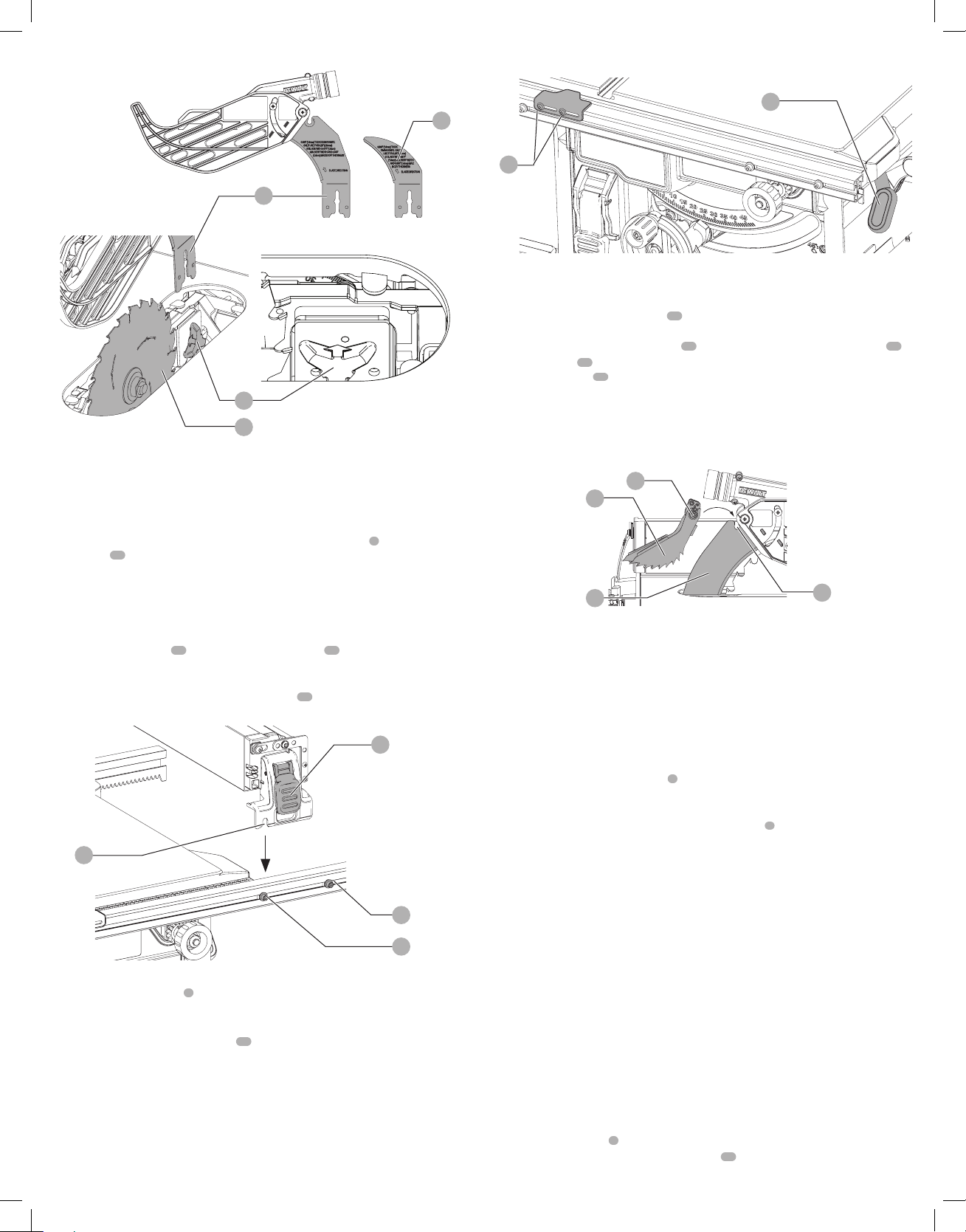
WARNING: Before inserting the battery into the table saw or operating the saw, always
inspect the blade guard assembly and riving knife for proper alignment and clearance with
saw blade. Check alignment after each change of bevelangle.
NOTE: DO NOT operate saw if riving knife lock pin is not locked into the blade guard or
rivingknife.
When properly aligned, the riving knife will be in line with the blade at both table top level,
and at the top of the blade. Using a straight edge, ensure that the blade
2
is aligned with the
riving knife
23
as shown in Figure G. Operate the blade tilt and height adjustments through the
extremes of travel and ensure the blade guard assembly clears the blade in all operations and
that the anti-kickback assembly isfunctioning.
Assembling the Rip Fence (Fig. H)
The rip fence can be installed in two positions on the right (position 1 for 0" to 20" ripping, and
position 2 for 4" to 24" ripping) and one position on the left of your tablesaw.
1. Align the locator pins
34
on the fence rails with the slots
35
on each fenceend.
2. Place fence onto the rail as shown in FigureH maintaining pin and slot alignment on both
ends of thefence.
3. Secure the rip fence by snapping down the latches
19
to the rails. Be sure to snap both front
and rear latches inplace.
34
34
19
35
Fig. H
Position 1
Position 2
Adjusting the Rip Scale (Fig. I)
1. Unlock the rail lock lever
5
.
2. Set the blade at 0° bevel and move the fence in until it touches theblade.
3. Lock the rail locklever.
4. Loosen the rip scale indicator screws
36
and set the rip scale indicator to read zero (O)
Retighten the rip scale indicator screws. The yellow rip scale (top) reads correctly only when
the fence is mounted on the right side of the blade and is in position 1 (for 0 to 20" ripping)
[not the 24" rip position]. The white scale (bottom) reads correctly only when the fence is
mounted on the right side of the blade and in position 2 (for 4" to 24" ripping).
A metric scale is available at an additional cost, refer to Accessories fordetails.
36
5
Fig. I
Anti-Kickback Assembly (Fig. J)
WARNING: To reduce the risk of serious personal injury, the anti-kickback assembly must be
in place for all possiblecuts.
1. Remove the anti-kickback assembly
14
from the storage position by depressing the stem.
Refer toStorage.
2. Locate the anti-kickback mounting slot
37
at the top rear of the blade guard assembly
11
.
3. Align the stem
38
with the mounting slot. Depress the stem and push down on the anti-
kickback assembly
14
until it snaps and locks intoplace.
4. To remove the anti-kickback assembly, depress the stem and pull up and out of the
mountingslot.
With battery removed, operate the blade tilt and height adjustments through the extremes of
travel and ensure the blade guard assembly clears the blade in all operations and that the anti-
kickback assembly isfunctioning.
Fig. J
14
37
11
38
Bench Mounting (Fig. A)
NOTE: A portable table saw stand is designed for use with this saw and is available at a local
DEWALT
dealer or service center at extracost.
WARNING: To reduce the risk of serious personal injury, turn unit off and remove the
battery pack before making any adjustments or removing/installing attachments
oraccessories. An accidental start-up can causeinjury.
WARNING: To reduce the risk of injury, the saw must be secured to prevent unintended
movement duringuse.
The table saw must be securely mounted on a stand, workbench or other rigid and stable support
so that the saw does not move while cutting and cannot be overturned by large overhanging
pieces of material. Four mounting holes
9
are provided in the metal frame to allow the table saw
to be secured to a stand or other means ofsupport.
1. Center the saw on the desired, stable worksurface.
2. Drive four 3-1/2" (88.9 mm) long screws through the holes
9
in the metal frame. Make sure
the screws extend through the frame and securely attach to the supporting worksurface.
NOTE: If marring the supporting work surface is a concern, the table saw can be mounted to
scrap wood which can then be clamped onto the desired worksurface.
3. Cut a piece of 3/4" (19 mm) plywood to fit beneath the footprint of thesaw.
4. Screw the saw to the plywood and clamp the overhang of the plywood to the work surface. If
the screws protrude through the plywood base, set it on two scrap pieces of material of equal
thickness and attach them to the edges of the plywood to hold the saw further off of the
work surface and prevent the screws from marring thesurface.
ASSEMBLY AND ADJUSTMENTS
WARNING: To reduce the risk of serious personal injury, turn unit off and remove the
battery pack before making any adjustments or removing/installing attachments
oraccessories. An accidental start-up can causeinjury.
NOTE: This saw is fully and accurately adjusted at the factory at the time of manufacture. If
readjustment due to shipping and handling or any other reason is required, follow the sections
below to adjust thissaw.
Once made, these adjustments should remain accurate. Take a little time now to follow these
directions carefully to maintain the accuracy of which this saw iscapable.
Rail Lock Adjustment (Fig. I, K)
(Tightening Fence Clamping System)
1. Lock the rail lock lever
5
.
2. On the underside of the saw, loosen the jam nut
39
.
Loading ...
Loading ...
Loading ...