Loading ...
Loading ...
Loading ...
8
3. Tighten the hex rod
40
until the spring on the locking system is more compressed, (not fully
compressed) creating the desired tension on the rail lock lever. Retighten the jam nut against
the hexrod.
4. Check that the fence does not move when the lock lever is engaged. If the fence is still loose,
tighten the springfurther.
Fig. K
39
40
Rip Scale Adjustment
See Adjusting the Rip Scale underAssembly.
Adjusting Blade Alignment (Fig. L)
(Blade Parallel to Miter Slot)
WARNING: Cut Hazard. Check the blade at 0˚ and 45˚ to make sure blade does not hit the
throat plate, causing personalinjury.
If the blade appears to be out of alignment with the miter slot on the table top, it will require
calibration for alignment. To realign the blade and miter slot, use the following procedure:
WARNING: To reduce the risk of serious personal injury, turn unit off and remove the
battery pack before making any adjustments or removing/installing attachments
oraccessories. An accidental start-up can causeinjury.
41
Fig. L
1. Using a 5mm hex wrench, loosen rear pivot bracket fasteners
41
just enough to allow the
bracket to move side-to-side.
2. Adjust the bracket until the blade is parallel to the miter gaugeslot.
3. Tighten the rear pivot bracket fasteners to 110–120 in-lbs (12.5–13.6 Nm).
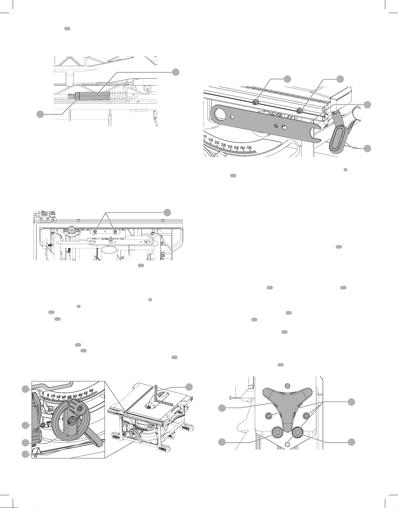
Bevel Stop and Pointer Adjustment (Fig. M)
1. Raise the blade fully by rotating the blade height adjustment wheel
6
clockwise until itstops.
2. Unlock the bevel lock lever
7
by pushing it up and to the right. Loosen the bevel
stopscrew
42
.
3. Place a square
45
flat against the table top and against the blade between teeth, as shown
in FigureM. Ensure the bevel lock lever is in its unlocked, or up,position.
4. Using the bevel lock lever, adjust the bevel angle until it is flat against thesquare.
5. Tighten the bevel lock lever by pushing itdown.
6. Turn the bevel stop screw
42
to rotate the cam until it firmly contacts the bearing block.
Tighten the bevel stop screw
42
.
7. Check the bevel angle scale. If the pointer does not read 0°, loosen pointer screw
44
and
move the pointer so it reads correctly. Retighten the pointerscrew.
8. Repeat at 45°, but do not adjustpointer.
45
44
42
6
7
Fig. M
Fence Alignment Adjustment (Fig. H, N)
(Blade Parallel to Fence)
If you experience fence alignment problems and want to correct an out of parallel alignment
between the fence and the blade, be sure to check the alignment of the blade to the miter slot
first. After confirming that those elements are aligned, proceed with alignment of the blade to
the fence using the following procedure:
Position 2Position 1
Fig. N
34 34
21
5
Position 1 Fence Alignment
1. Install the fence in position 1 (Refer to Figure H) and unlock the rail lock lever
5
. Locate both
locator pins
34
that support the fence on the front and rearrails.
2. Loosen the rear locator pin screw and adjust the allignment of the fence in the groove until
the fence face is parallel to the blade. Make sure you measure from the fence face to the front
and back of the blade to ensurealignment.
3. Tighten the locator pinscrew.
4. Check rip scale pointeradjustment.
NOTE: Follow the Position 1 Fence Alignment instructions for aligning the fence on the left of
theblade.
Position 2 Fence Alignment
1. To align position 2 fence locator pins, ensure position 1 pins have been aligned, refer to
Position 1 FenceAlignment.
2. Loosen the position 2 locator pins, then using holes in the blade wrench
21
as a guide for
positioning, align the pins (Fig.N).
3. Tighten the locator pins (front and rear).
Aligning Riving Knife to Blade (Fig. O)
1. Remove the throat plate. Refer to Removing the Throat Plate underAssembly.
2. Raise the blade to full depth of cut and 0° bevelangle.
3. Locate the three small set screws
50
adjacent to the riving knife lock knob
33
. These screws
will be used to adjust the riving knifeposition.
4. Lay a straight edge on the table against two blade tips. The riving knife should not touch the
straightedge.
5. If needed, loosen the two larger lock screws
51
.
6. Use the small set screws
50
to adjust the riving knife position. Lay the straight edge on the
opposite side of the blade and repeat adjustments asneeded.
7. Lightly tighten the two larger lock screws
51
.
8. Place a square flat against the riving knife to verify the riving knife is vertical and in-line with
theblade.
9. If needed, use the set screws to bring the riving knife vertical with thesquare.
10. Repeat step 4 to verify position of rivingknife. Repeat 5 thru 9 ifnecessary.
11. Fully tighten the two larger lock screws
51
.
Fig. O
50
5151
33
Saw Blades
WARNING: Riving knives must be matched to saw blade dimensions in order to function
effectively. Refer to Splitter and Riving KnifeSelection. Use only 8-1/4" (210mm)
diameter blades with this tablesaw.
Loading ...
Loading ...
Loading ...