Loading ...
Loading ...
Loading ...
6
Specifications
Table Size 19 X 19" (485 x 485mm)
Miter Angle 30° left and right
Bevel Angle -2° to 47° left
Blade Size 8–1/4" (210mm)
Max. Cut Depth, 0° Bevel 2–9/16" (65mm)
Max. Cut Depth, 45° Bevel 1–3/4" (45mm)
RPM, no load 5800
Unpacking (Fig. D)
WARNING: To reduce the risk of injury, DO NOT install the battery pack until the table saw is
completely assembled and you have read the entire instructionmanual.
Open the box and slide the saw out, as shown in FigureD.
Fig. D
Carefully unpack the table saw and all loose items from the carton. Examine all parts to make sure
that parts have not been damaged during shipping. If any parts are missing or damaged, contact
your dealer to replace them before attempting to assemble thetool.
COMPONENTS (FIG. A)
WARNING: Never modify the power tool or any part ofit. Damage or personal injury
couldresult.
Refer to Figure A at the beginning of this manual for a complete list ofcomponents.
INTENDED USE
This table saw is intended for use by construction professionals for use in ripping, crosscutting,
mitering, beveling and non-through cutting applications in wood, plastic, and other
softmaterials.
DO NOT use for cutting metal, cement board, ormasonry.
DO NOT use dado or shaping cutter heads on thissaw.
DO NOT use under wet conditions or in presence of flammable liquids orgases.
DO NOT let children come into contact with the tool. Supervision is required when inexperienced
operators use thistool.
ASSEMBLY
WARNING: Shock Hazard. To reduce the risk of serious personal injury, turn unit off
and disconnect the battery pack before attempting to move it, change accessories
or make any adjustments. An accidental start-up can causeinjury.
Assembly Order (Fig. A)
1. Unlock and remove the throat plate
17
. Refer to: Removing the Throat Platesection.
2. Make sure blade is installed correctly and arbor nut is tight. Use wrenches
21
stored on the
tool. Refer to FigureA.
3. Position the blade guardassembly
11
.
4. Attach anti-kickback assembly
14
to the guardassembly.
5. Install and lock throat plate
17
. (NOTE: Adjust leveling screws before proceeding. Refer to
Installing the Throat Plate.)
6. Attach the rip fence
18
. (NOTE: Adjust rip scale before proceeding. Refer to Adjusting the
RipScale.)
NOTE: To attach this table saw to a stand, please follow the instructions included with the
standassembly.
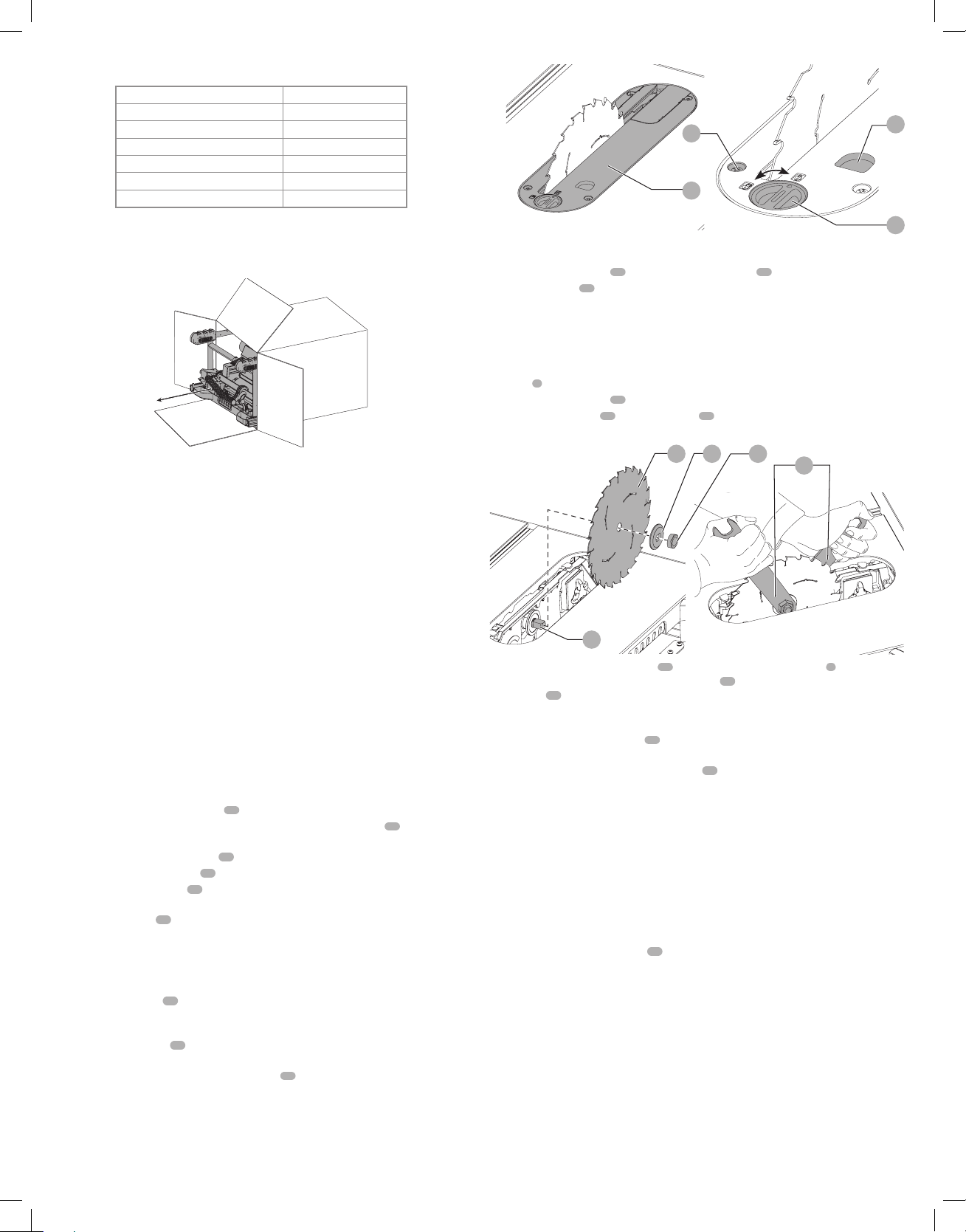
Installing the Throat Plate (Fig. E)
1. Align the throat plate
17
as shown in FigureE, and insert the tabs on the back of the throat
plate into the holes on the back of the tableopening.
2. Rotate cam counterclockwise until the front of throat plate drops into place. Secure by
rotating cam lock knob
27
clockwise 1/4 turn (when cam lock is under the table holding the
throat plate in place).
3. The throat plate includes four adjustment screws
28
which raise or lower the throat plate.
When properly adjusted, the front of the throat plate should be flush or slightly below the
surface of the table top and secured in place. The rear of the throat plate should be flush or
slightly above the tabletop.
Fig. E
17
29
27
28
Removing the Throat Plate
1. Remove the throat plate
17
by turning the cam lock knob
27
1/4 turn counterclockwise
2. Using finger hole
29
on the plate, pull throat plate up and forward to expose the inside of
the saw. DO NOT operate the saw without the throatplate.
WARNING: To reduce the risk of serious personal injury, the throat plate must be locked in
place at alltimes.
Installing/Replacing the Blade (Fig. A, E, F)
1. Raise the saw blade arbor to its maximum height by turning the blade height adjustment
wheel
6
clockwise.
2. Remove the throat plate
17
.
3. Remove the arbor nut
30
and clamp washer
31
from the saw arbor by
turningcounterclockwise.
Fig. F
2
31 30
32
21
4. Place the saw blade on to the arbor
32
making sure the teeth of the blade
2
point down at
the front of the table. Assemble the clamp washer
31
and arbor nut to the arbor and tighten
arbor nut
30
as far as possible by hand, making sure that the saw blade is against the inner
flange and the clamp washer is against the blade. Ensure the largest diameter of the clamp
washer is against the blade. Ensure the arbor and clamp washer are free from dust anddebris.
5. Use the open end of the wrench
21
to keep the arbor from rotating when tightening the
arbornut.
6. Using the other wrench, tighten the arbor nut
30
by turning itclockwise.
7. NOTE: Different types of blades make different kerfs (width of cuts). Therefore, it is necessary
to check adjustment of rip scale when changing blades. Replacement blade MUST not
exceed the thickness stated on the riving knife. The riving knife provided with the saw is
1.6mmthick.
Installing/Removing the Blade Guard Assembly and Riving Knife
(Fig. G)
WARNING: Use blade guard assembly for all thru-sawing.
NOTE: The saw is shipped with the non thru sawing riving knifeinstalled.
1. Raise the saw blade arbor to its maximumheight.
2. Loosen the riving knife lock knob
33
(minimum of three turns).
3. To disengage riving knife lock pin, push lock knob toward the riving knife as indicated by the
yellow arrows on theknob.
4. While pushing the lock knob, lift the riving knife out of the clamp. Then slide the blade guard
assembly into the clamp until it bottomsout.
WARNING: Do not insert both blade guard assembly and riving knife into the clamp at the
sametime.
5. Release the lock knob to engage the lock pin. Give the blade guard a slight pull upwards to
ensure pin is engaged.
6. Tighten the riving knife lockknob.
7. Reinstall the throatplate.
8. To remove the bladed guard assembley, follow these steps in reverseorder.
NOTE: Follow the same steps above for riving knifeinstalation.
Loading ...
Loading ...
Loading ...