Loading ...
Loading ...
Loading ...
2828
GAS CONNECTION
AND TRANSFORMATION
GAS CONNECTION
(UNI CIG 7129/7131)
The appliances must be attached to the gas pipeline with rigid or exible metal pipes (maximum
length 2 metres) suitable for gas appliances. The connection pipes and their maximum length must
comply with the applicable standards, replaced before the expiry date (if indicated on the pipe) and
connected to the appliance by a coupling:
a) directly on the connection ISO R228 (with ISO R228 sealing gasket), if the pipe’s route allows it
g. 3
b) •if the connection is to be directed (right-left-low), the supplied connection (g. 4a - g. 4b) must
be used.
•for the seal between the pipe and the ramp gas use the gasket (ISO R228) g. 4a
•for the seal on the thread (ISO R7) it is necessary to use conical connections on the thread (g.
4b)
•to improve the seal, a mastic suitable for GAS can be used.
When the gas is drawn from a cylinder, the appliance, supplied with a pressure regulator compliant
with standard UNI-CIG 7432, must be connected: with exible stainless steel pipes along the wall,
according to standard UNI-CIG 9891, with 2 metres maximum extension and sealing gasket accor-
ding to standard UNI 9264.
PRECAUTIONS FOR USING THE PRODUCT WITH GPL GAS:
The gas taps tted in your kitchen must work with liquid gas of controlled quality, supplied at the
proper nominal pressure. This pressure must be guaranteed by a special certied pressure regulator.
The use of gas coming from uncertied sources and/or the improper use of the GPL cylinder as well
as the relative regulator, can invalidate the product’s guarantee. It is especially necessary to avoid
all the situations that could pollute the gas with residues and impurities that, when introduced into
the gas circuit, can irreparably damage the control components such as taps and thermostats. It is
recommended to:
• use only GPL cylinders coming from ofcial retailers and authorised by the various manufacturers
• use the cylinders until empty without inclining or overturning them
• carry out regular cleaning of the lter at the pressure regulator inlet
BE CAREFUL:
When the connection is made, it is recommended to check the connections’ seal with special foams
(NO FLAMES).
IMPORTANT:
Periodically check the gas connection pipe’s good condition and replace it when there are signs of
anomalies.
Thi s appl iance i s sui t abl e f or connect i on w it h r i gi d pi pe or f l exi bl e hose. The i sol at i ng manual shut -of f val ve
connect ion point must be accessible when t he appliance is inst alled. The flexible hose assembly must be cert if ied
to AS/NZS 1869 class B or D, be of appropriate internal diameter for the total gas consumption, be kept as short
as possible (not exceeding 1200mm), must not be in cont act wit h t he floor or any hot or sharp surfaces. The hose
assembly must not be subject t o st rain, abrasion, kinking or deformat ion.
Nat ural Gas: t he supplied regulat or must be fit t ed t o t he appliance inlet connect ion. Gas pressure must be
adjusted t o 1.0 kPa when approximat ely 50% of t he burners are on high f lame, t he appliance t est point is locat ed
on the regulator.
ULPG: t he supplied t est point adapt or must be f it t ed t o t he appliance inlet connect ion. Gas pressure must be
adjusted t o 2.75 kPa, t he appliance t est point is locat ed on t he t est point adapt or.
Gas l eak age an d op er at i o n o f t h e ap pl i an ce mu st be t e st e d b y t h e i n st al l er b ef o r e l eav i n g. Ch eck b ur n er f l am es
are blue in colour, st able and complet ely ignit e at bot h high and low flame set t ings wit h no appreciable yellow
tipping, carbon deposition, lifting, floating, lighting back or objectionable odour. Test burners individually and in
combinat ion, When sat isfied wit h t he operat ion of t he cooker, please instruct t he user on t he correct met hod of
operation.
Over head clear ances—(M easur ement A) Range hoods and exhaust f ans shal l be i nst al l ed i n accor dance wi t h t he
manufacturer’s relevant instructions. However, in no case shall the clearance between the highest part of the
hob of the gas cooking appliance and a range hood be less than 600 mm or, for an overhead exhaust fan, 750
mm.
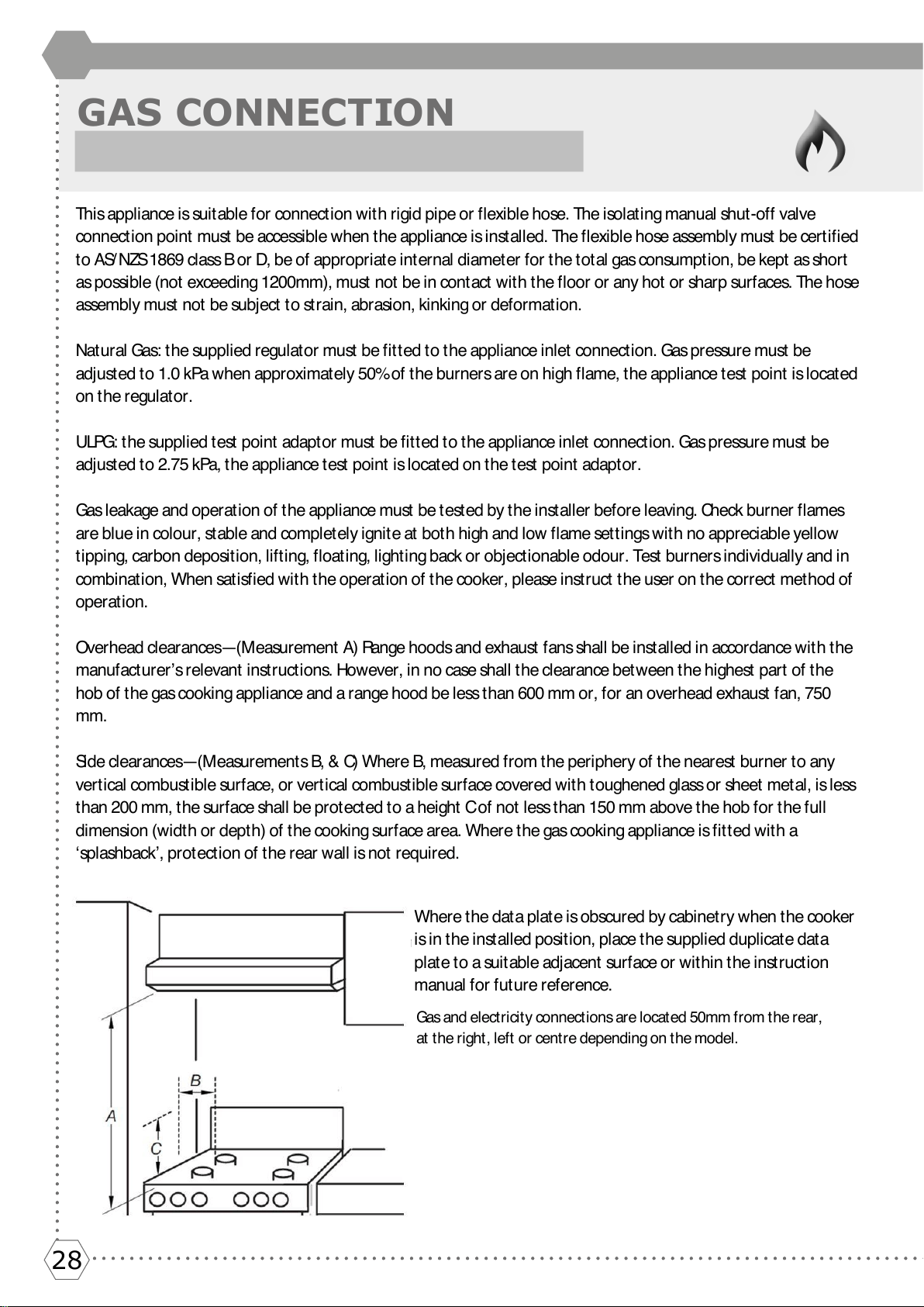
Si d e c l e a r a n c e s— ( M e a su r e m e n t s B, & C) W h e r e B , m e a su r e d f r o m t h e p e r i p h e r y o f t h e n e a r e st b u r n e r t o a n y
vertical combustible surface, or vertical combustible surface covered with toughened glass or sheet metal, is less
than 200 mm, the surface shall be protected to a height C of not less than 150 mm above the hob for the full
dimension (width or depth) of the cooking surface area. Where the gas cooking appliance is fitted with a
‘splashback’, protection of the rear wall is not required.
Where the data plate is obscured by cabinet ry when the cooker
is in the installed position, place the supplied duplicate data
plate to a suitable adjacent surface or within the instruction
manual for future reference.
Del et e
Gas an d e l ect r i ci t y co n nect i o n s ar e l o cat ed 50m m f r o m t h e r ear ,
at t he right , left or cent re depending on t he model.
Loading ...
Loading ...
Loading ...