
BUILT-IN COOKTOP OPERATING &
INSTALLATION MANUAL
H SERIES & HCB SERIES
2

3
OPEN 24
/
7
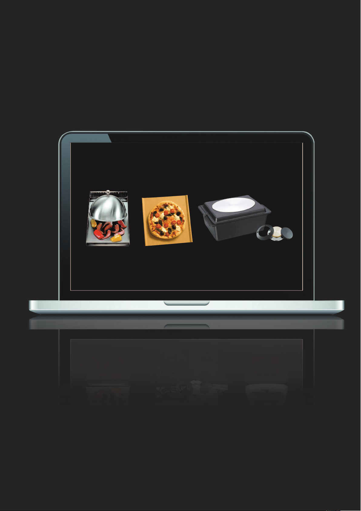
ILVE ACCESSORIES ONLINE SHOP
For a wide range of coee machines and other genuine
ILVE accessories at the click of a button
shop.ilve.com.au
4
As a part of our continued customer service
oering, you can now register your ILVE products online at
https://support.eurolinx.com.au//form/warrantyregistration
Just follow our simple online registration process.
Please ensure that you always keep your proof of purchase
in order for your warranty to remain valid should you ever
need to use it.
As always, you can contact us on
1300 856 411

5
iWarranty
REGISTER YOUR WARRANTY ONLINE NOW
GO TO: https://support.eurolinx.com.au/#/form/warrantyregistration
6
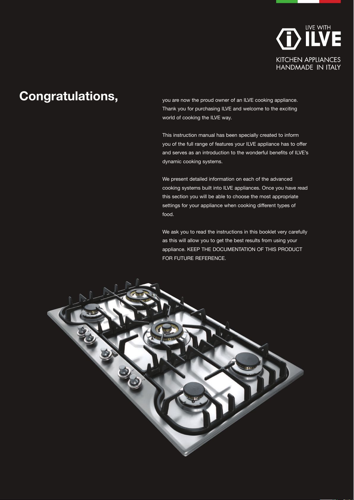
you are now the proud owner of an ILVE cooking appliance.
Thank you for purchasing ILVE and welcome to the exciting
world of cooking the ILVE way.
This instruction manual has been specially created to inform
you of the full range of features your ILVE appliance has to offer
and serves as an introduction to the wonderful benefits of ILVE’s
dynamic cooking systems.
We present detailed information on each of the advanced
cooking systems built into ILVE appliances. Once you have read
this section you will be able to choose the most appropriate
settings for your appliance when cooking different types of
food.
We ask you to read the instructions in this booklet very carefully
as this will allow you to get the best results from using your
appliance. KEEP THE DOCUMENTATION OF THIS PRODUCT
FOR FUTURE REFERENCE.
Congratulations,
22
Index
Important advice for safety ........................................................ 3
INSTRUCTIONS FOR USE ............................................................. 9
Lighting the burners ................................................................................ 9
Lighting the “DUAL” ring burner ............................................................... 10
Placement of the burners......................................................................... 11
Posizionamento delle griglie .................................................................... 13
Istruzioni per l’uso del FRY-TOP a gas ....................................................... 16
Barbecue a gas (optional) ....................................................................... 18
Grill electric barbecue ............................................................................. 19
MAINTENANCE AND CLEANI ..................................................... 21
INSTALLATION ..............................................................................22
Installation instructions .......................................................................... 22
Ventilation of the pre .............................................................................. 22
Fitting the cooking hob onto the base unit with door ................................... 22
Built-in installation ................................................................................. 23
Fitting the cooking hob ........................................................................... 23
BUILT IN TOPS’ HOLE SIZE ....................................................... 24
Electric connection ................................................................................. 27
Gas connection ...................................................................................... 29
ADJUSTMENT ................................................................................. 30
Adjustment adapting to different types of gas ............................................ 30
Replacement of the injectors ................................................................... 33
Minimum adjustment .............................................................................. 35
WIRING DIAGRAMS .................................................................... 36
PROBLEM SOLVING ..................................................................... 38
NOTES .............................................................................................. 39
important warnings Iinstructions for use maintenance and cleaning
Parti elettriche Problem solving
Installation
Gas
U
S
E
R
I
N
S
T
A
L
L
E
R
Pl ace men t o f t he gr i l l
Instructions for use of the Gas Fry-Top
El e c t r i c a l
3333333
U
S
E
R
GB
IMPORTANT
SAFETY WARNINGS
FEATURES OF THE APPLIANCES
The data plate, as well as being on the cover, is also on the a plian-
ce.
BE CAREFUL
1. These warnings refer to different appliance models. Be sure that
you have correctly identied the model that you possess (see the
data plate).
2. These warnings are valid for the countries listed on the plate.
3. Read the instructions booklet carefully, before using the applian-
ce. This contains very important information concerning safety du-
ring installation, use and maintenance. The instructions booklet
must be kept with care for later consultation and for the identica-
tion of the serial number.
4. The electrical safety of this appliance is only guaranteed if it is
properly earthed as required by the regulations in force. It is fun-
damental to ensure that these regulations have been respected;
if you are in doubt, call a skilled technician to have the electrical
system checked in detail. The manufacturer does not accept any
responsibility for damage caused by a bad earthing system.
5. Before connecting the cooker, check that the technical fe-
atures on the data plate correspond perfectly with those of
the electric system and of the gas mains. The installation /
regulation must be made by qualied staff.
6. Check that air circulates freely around the appliance . This ap-
pliance is not connected to a combustion products evacuation de-
vice therefore the premises’ ventilation system must be considered
carefully and according to the rules in force.
Del et e
44
IMPORTANT
SAFETY WARNINGS
7. When using gas appliances, heat and dampness are generated
inside the premises. Good ventilation of the kitchen is required by:
keeping the natural vents open or installing a mechanical ventila-
tor (hood). Intensive and prolonged use of the appliance can make
supplementary ventilation necessary: opening a window or increa-
sing the power of the hood.
8. The power cable is supplied without a plug. To connect please
refer to the “electric connection” paragraph. We advise not using
adapters, multiple sockets or extensions.
9. Disconnect the power supply when the appliance is not used for
some time, switch off the mains and turn off the gas.
10. When the electric cable is damaged, it must be replaced by cal-
ling an after saves service approved by the manufacturer.
11. The appliance must only be used for the purposes for which
it was intended (cooking). Any other use (for example, heating a
room) is incorrect and therefore dangerous. The manufacturer de-
clines all responsibility for damage caused by similar incorrect uses.
12. The use of any electrical appliance requires that the following
rules are respected:
13. The use of any electrical appliance requires that the following
rules are respected:
A. never touch the appliance when you have wet or damp
hands or feet;
B.
never use the appliance in your bare feet;
C.
avoid using extensions or, if this is inevitable, take all
possible precautions;
D. Never pull on the electric cable to remove it from the
power socket;
and plug are supplied.
5555555
U
S
E
R
GB
IMPORTANT
SAFETY WARNINGS
do not expose the appliance to weathering (rain, sun, etc.);
Be careful: the accessible parts may become very hot
during use. Keep children less than 8 years old away from
the cooker, if not continuously supervised. This appliance can
be used by children from 8 years old and by persons with
reduced physical, sensory or mental abilities otherwise with
lack of experience and knowledge if they are adequately su-
pervised or if they have been instructed on the safe use of
the cooker and if they realise the relevant dangers. Children
must not play with the cooker. Cleaning and maintenance
must not be done by unsupervised children.
E.
F.
14. BE CAREFUL: some accessible parts may have high tempera-
tures during use: keep children at a distance.
15. Before cleaning the appliance or carrying out maintenance, di-
sconnect the power supply by removing the plug from the socket or
switching the current off through the switch provided.
16. In the event of faults or malfunctions, switch off the
appliance, turn off the gas tap and do not attempt to make
any repairs; these must be carried out exclusively by an ap-
proved service centre. Always insist on original spare parts.
Failure to follow these indications may endanger the safety
of the cooker.
17. Never place unsteady or deformed pans on the burners
or on the electric hotplates as they could overturn acciden-
tally.
18. When the appliance is not in use, ensure that all the
knobs are in the “ ”/ “ ” / OFF position.
Del et e
66
IMPORTANT
SAFETY WARNINGS
19. Never leave the hotplate switched on without a pan on
it, otherwise it will reach a very high temperature quickly
and the cooker or furniture in the vicinity could be damaged.
20. Some parts of the cooker, especially the electric hotpla-
tes, stay warm for a long time after use. Be careful not to
touch them.
21. Do not keep below the cooker and do not use inam-
mable liquids (detergents, sprays, alcohol, petrol ...) near
the cooker when it is switched on.
22. If using small electric appliances near the hob, be sure
to prevent the electric cable from touching the appliance’s
hot parts.
23. In order to work properly, gas cookers must be installed in well
ventilated premises. Ensure that installation is carried out accor-
ding to the indications given in the “Installation” chapter.
24. The materials used in the construction of our electri-
cal appliance are compatible with the environment and the-
refore recyclable. Packaging remains should not be left within the
reach of children, but disposed of using specic recycling channels.
The possibility of disposing of your equipment through your local
retailer and/or town council should be investigated; remember to
make your appliance unusable before scrapping it.
25. In case the tap is hard or precarious to turn, do not intervene
on the tap but shut off the gas and have the authorised service
centre intervene.
26. Do not modify or change the cooker.
7777777
U
S
E
R
GB
IMPORTANT
SAFETY WARNINGS
27. Be careful: leaving the unguarded cooker with objects, fats
and oils can be dangerous and can cause a re.
28. The cooker must be used by responsible people. Be careful:
the use of inappropriate or unsuitable protections can cause res
and / or damage.
29. Be careful: cooking with fat or oil can be dangerous or cause
res.
30. Be careful: re danger: do not keep objects on cooking sur-
faces.
31. Be careful: in the case of re never attempt to extinguish a
ame / re with water, but turn the appliance off and cover the a-
me with a lid or with a reproof cover.
32. Be careful: metal objects such as knives, forks, spoons or lids
should not be placed on the cooker because they can get hot.
33. Be careful: do not use gas burners if the ame is unstable.
34. Ensure that the ame diffusers are properly positioned in their
seats with their respective caps.
35. Do not leave the cooker unguarded during any cooking that
can spit fats or oils.
36. Do not touch the appliance’s heating elements when on. Let
them cool before proceeding with any cleaning.
37. Food preparation in plastic or aluminium containers on hot co-
oking zones is forbidden just like the positioning on the cooking
surfaces of plastic or aluminium foil objects.
Del et e
88
38. Do not cover the burners or the hob with tinfoil.
39. Do not use the appliance’s surface as a work top, sharp objects
might scratch it.
40. Containers or grills must be positioned within the hob’s peri-
meter.
41. Be careful: do not use frying pans, saucepans, grills or stones
for grilling of a greater size than the maximum ones indicated for
each single burner; above all they must not cover more than one
burner at the same time.
The heat accumulation might damage the cooker.
42. In case of liquid spilling over, remove it from the hob.
43. Do not place empty saucepans on the cooking areas.
44. The cooking zonesareas, must not work in vainempty, without
saucepans.
IMPORTANT
SAFETY WARNINGS
45. DO NOT USE OR STORE FLAMMABLE MATERIALS NEAR THIS APPLIANCE
46. DO NOT SPRAY AEROSOLS IN THE VICINITY OF THIS APPLIANCE WHILE IT IS IN OPERATION.
47. DO NOT USE THIS APPLIANCE AS A SPACE HEATER
48. DO NOT MODIFY THIS APPLIANCE
49. DO NOT PLACE ARTICLES ON OR AGAINST THIS APPLIANCE
50. Do not place anything, e.g. flame tamer or griddle plate between pan and pan support. Do
not remove the pan support and enclose the burner with a wok stand, only use the wok support
suppl ied. Do not use l ar ge pot s or heavy w ei ght s whi ch can bend t he pan suppor t or def l ect
flame onto the hotplate. Locate pan centrally over the burner so that it is stable and does not
overhang the appliance.
Not suit able f or aft ermarket lids or covers
9999999
U
S
E
R
GB
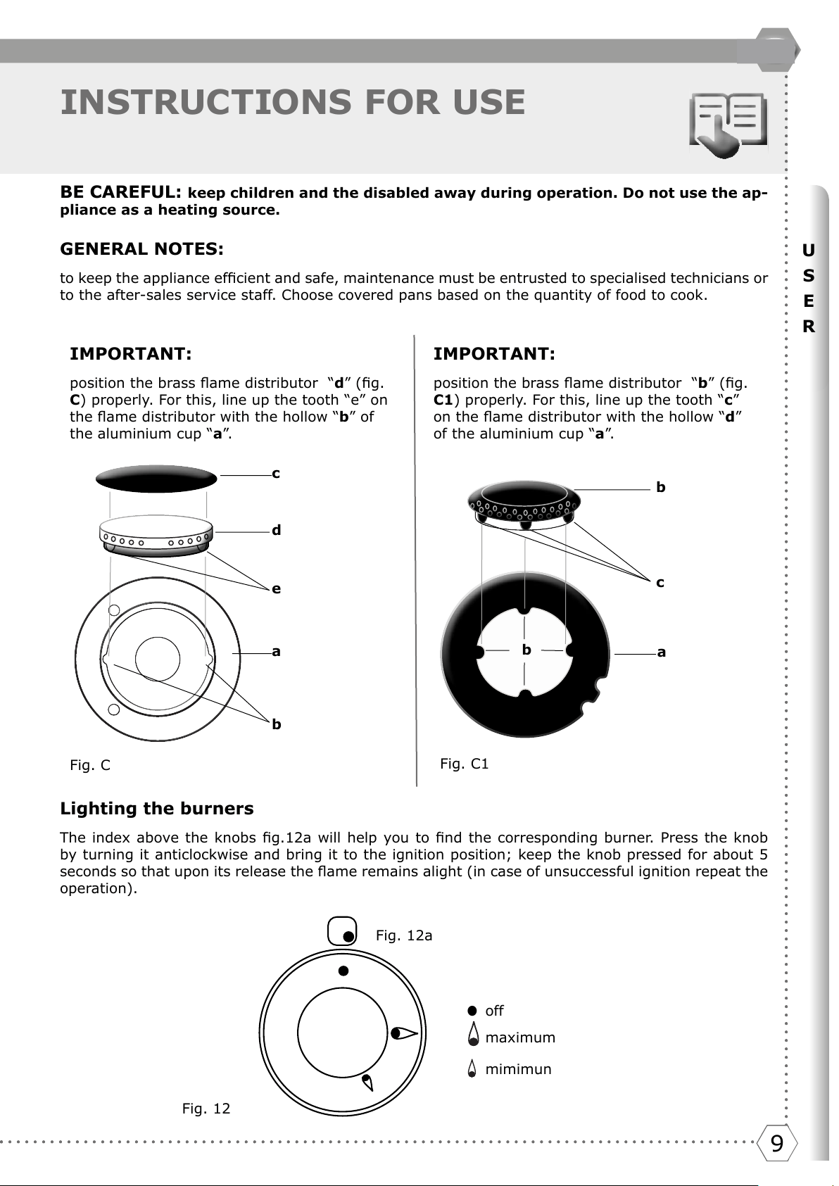
INSTRUCTIONS FOR USE
BE CAREFUL: keep children and the disabled away during operation. Do not use the ap-
pliance as a heating source.
GENERAL NOTES:
to keep the appliance efcient and safe, maintenance must be entrusted to specialised technicians or
to the after-sales service staff. Choose covered pans based on the quantity of food to cook.
Lighting the burners
The index above the knobs g.12a will help you to nd the corresponding burner. Press the knob
by turning it anticlockwise and bring it to the ignition position; keep the knob pressed for about 5
seconds so that upon its release the ame remains alight (in case of unsuccessful ignition repeat the
operation).
Fig. C
Fig. 12a
Fig. C1
Fig. 12
off
mimimun
maximum
a
c
d
e
b
IMPORTANT:
position the brass ame distributor “d” (g.
C) properly. For this, line up the tooth “e” on
the ame distributor with the hollow “b” of
the aluminium cup “a”.
IMPORTANT:
position the brass ame distributor “b” (g.
C1) properly. For this, line up the tooth “c”
on the ame distributor with the hollow “d”
of the aluminium cup “a”.
a
b
c
b
●
Del et e
1010
INSTRUCTIONS FOR USE
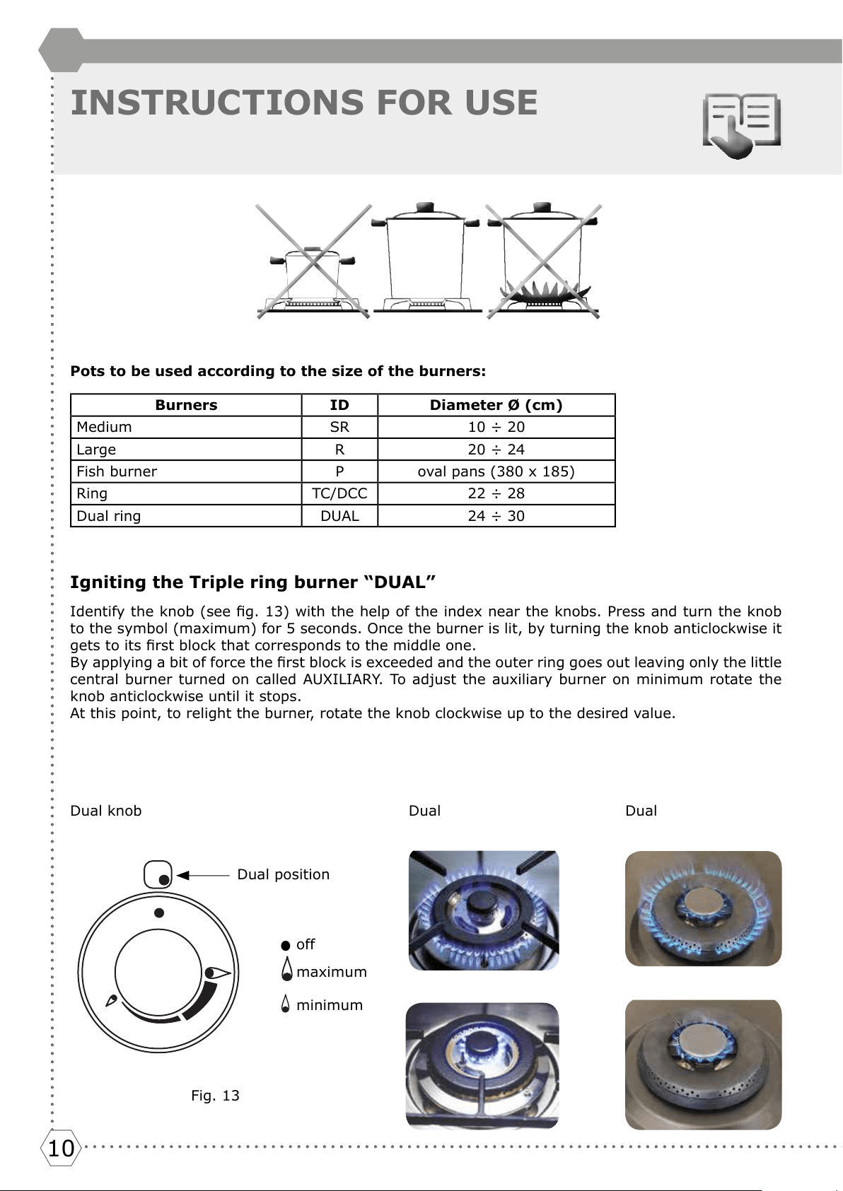
Pots to be used according to the size of the burners:
Burners ID Diameter Ø (cm)
Medium SR 10 ÷ 20
Large R 20 ÷ 24
Fish burner P oval pans (380 x 185)
Ring TC/DCC 22 ÷ 28
Dual ring DUAL 24 ÷ 30
Igniting the Triple ring burner “DUAL”
Identify the knob (see g. 13) with the help of the index near the knobs. Press and turn the knob
to the symbol (maximum) for 5 seconds. Once the burner is lit, by turning the knob anticlockwise it
gets to its rst block that corresponds to the middle one.
By applying a bit of force the rst block is exceeded and the outer ring goes out leaving only the little
central burner turned on called AUXILIARY. To adjust the auxiliary burner on minimum rotate the
knob anticlockwise until it stops.
At this point, to relight the burner, rotate the knob clockwise up to the desired value.
DualDual
●
off
maximum
minimum
Fig. 13
Dual knob
Dual position
11111111111111
U
S
E
R
GB
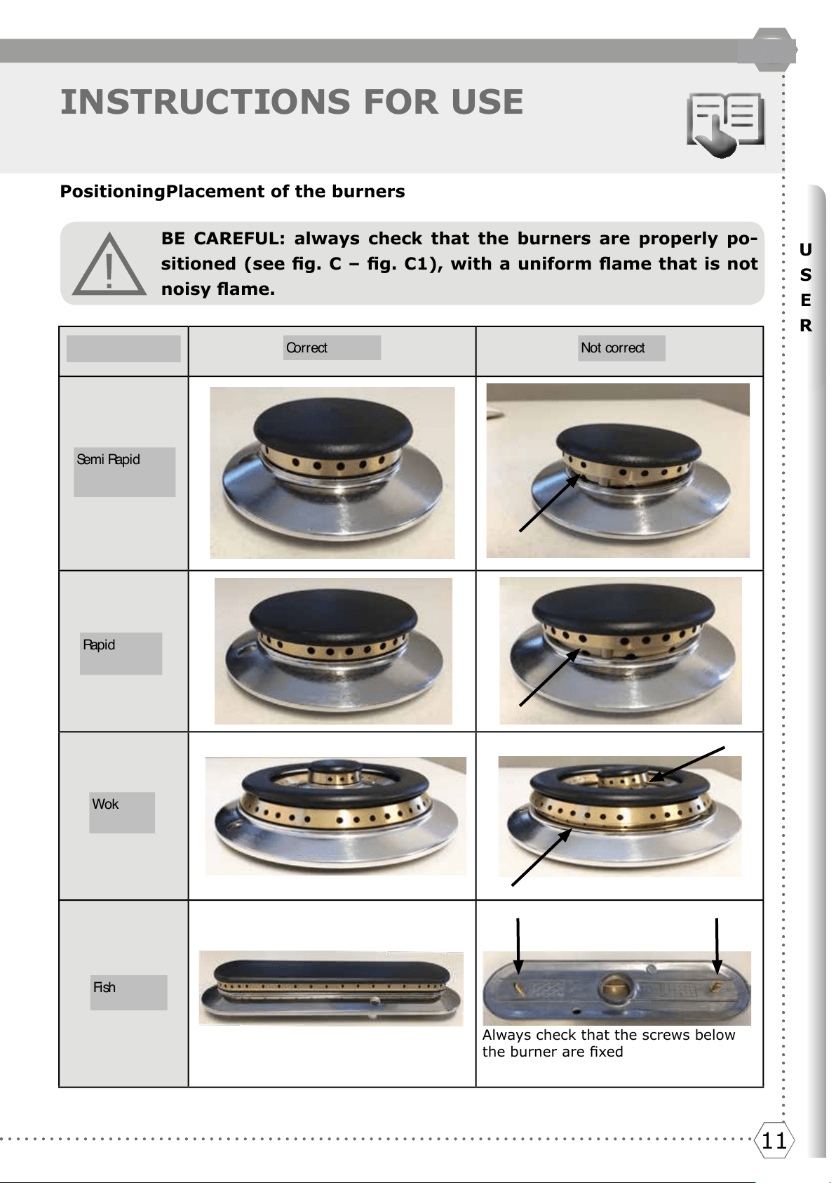
INSTRUCTIONS FOR USE
BE CAREFUL: always check that the burners are properly po-
sitioned (see g. C – g. C1), with a uniform ame that is not
noisy ame.
PositioningPlacement of the burners
Always check that the screws below
the burner are xed
BRUCIARORI CORRETTO ERRATO
Semi Rapido
(medio)
Rapido
(grande)
Corona
Dual
Pescera
Del et e
Co r r e c t
Not correct
Se m i R ap i d
Del et e
Ra p i d
Wok
Fi sh
1212
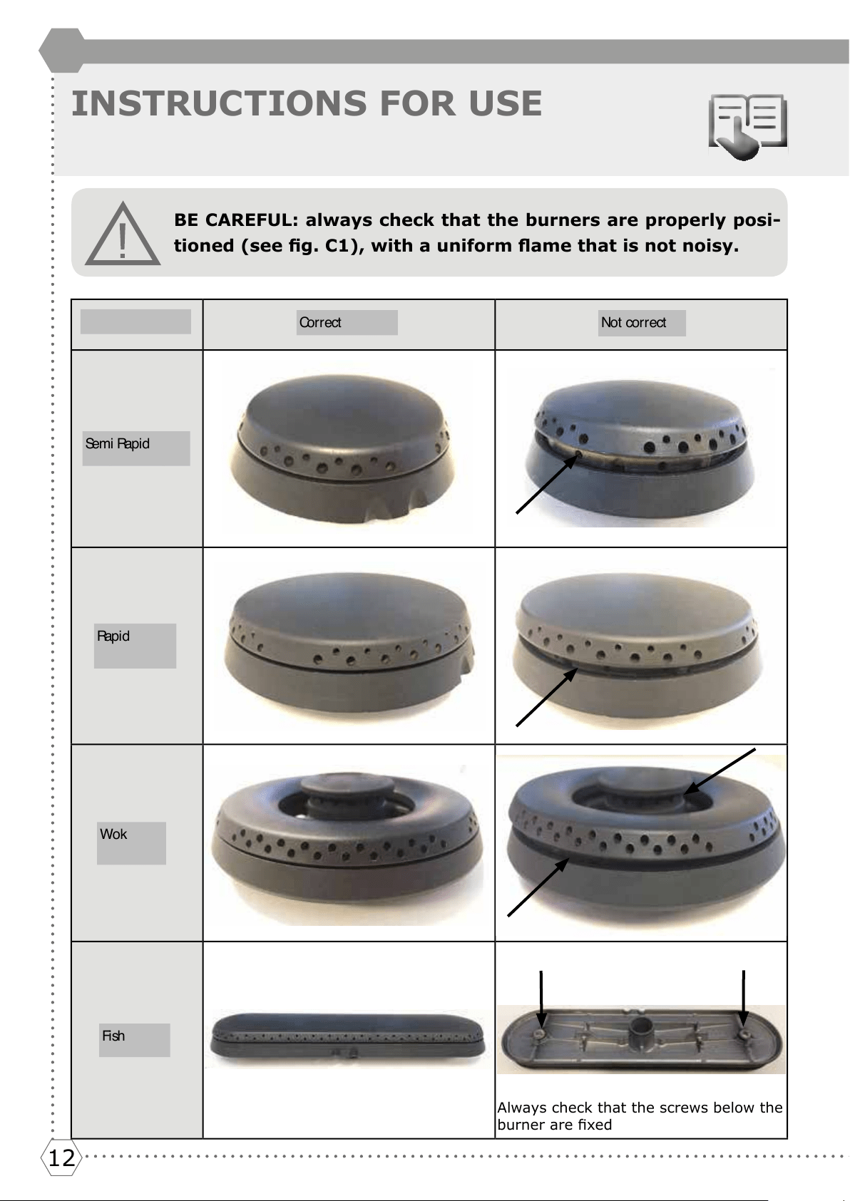
INSTRUCTIONS FOR USE
BE CAREFUL: always check that the burners are properly posi-
tioned (see g. C1), with a uniform ame that is not noisy.
Always check that the screws below the
burner are xed
BRUCIARORI CORRETTO ERRATO
Semi Rapido
(medio)
Rapido
(grande)
Corona
Dual
Pescera
Se m i R ap i d
Ra p i d
Wok
Fi sh
Co r r e c t
Not correct
Del et e
13131313131313
U
S
E
R
GB
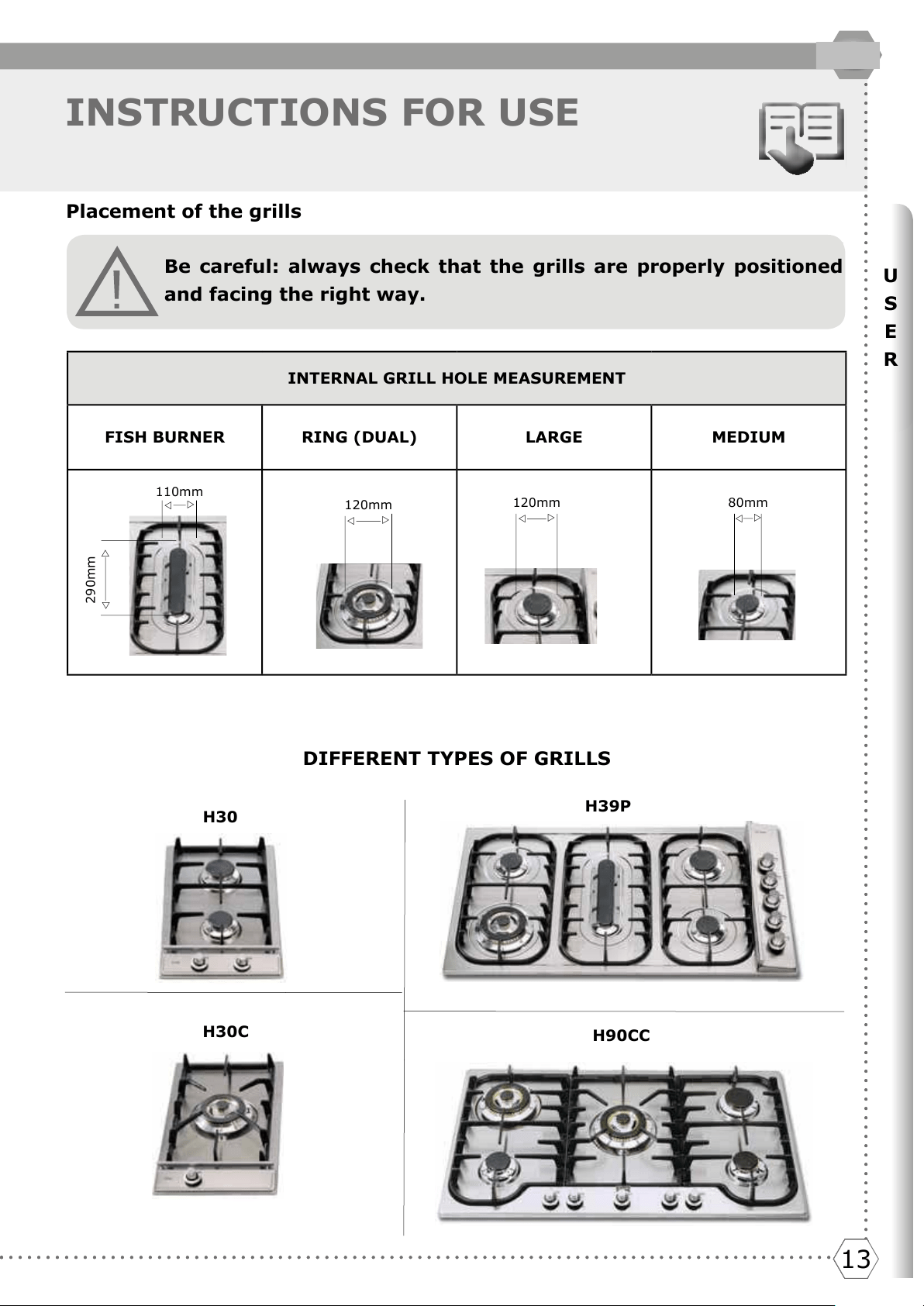
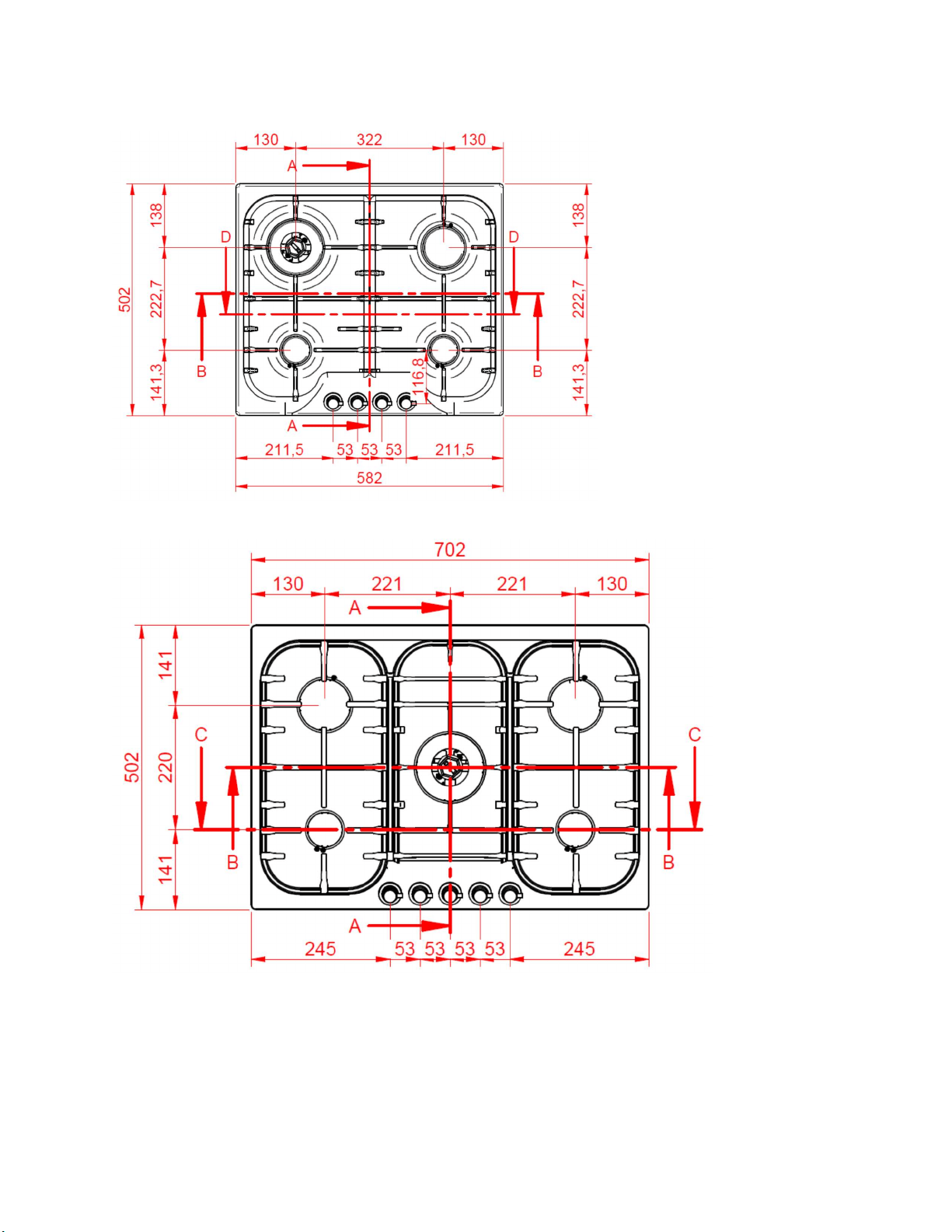
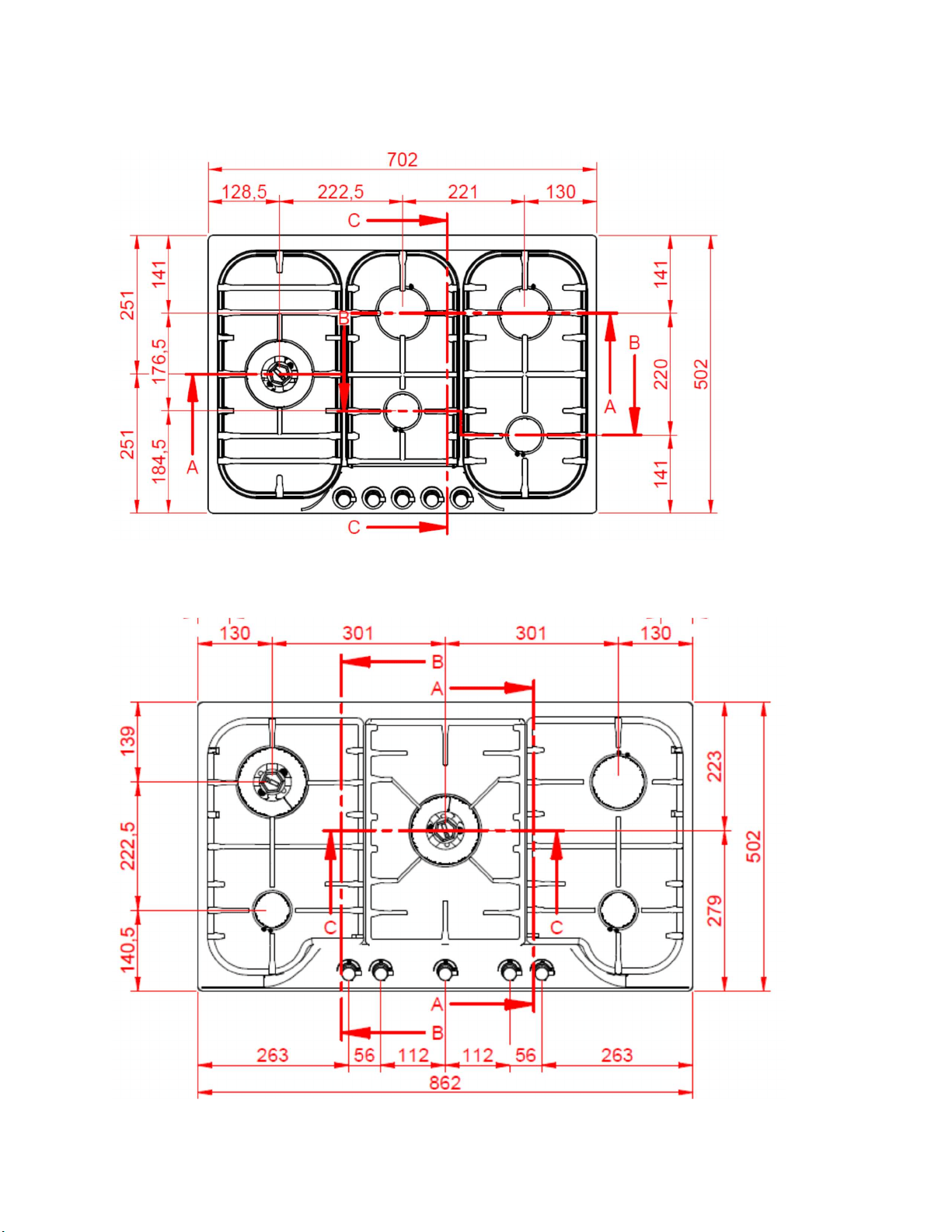
INSTRUCTIONS FOR USE
Be careful: always check that the grills are properly positioned
and facing the right way.
H30
H30C
H39P
H90CC
INTERNAL GRILL HOLE MEASUREMENT
FISH BURNER RING (DUAL)
LARGE MEDIUM
U
U
U
U
U
U
U
U
U
U
290mm
110mm
120mm
120mm
80mm
DIFFERENT TYPES OF GRILLS
Placement of the grills
Del et e
1414
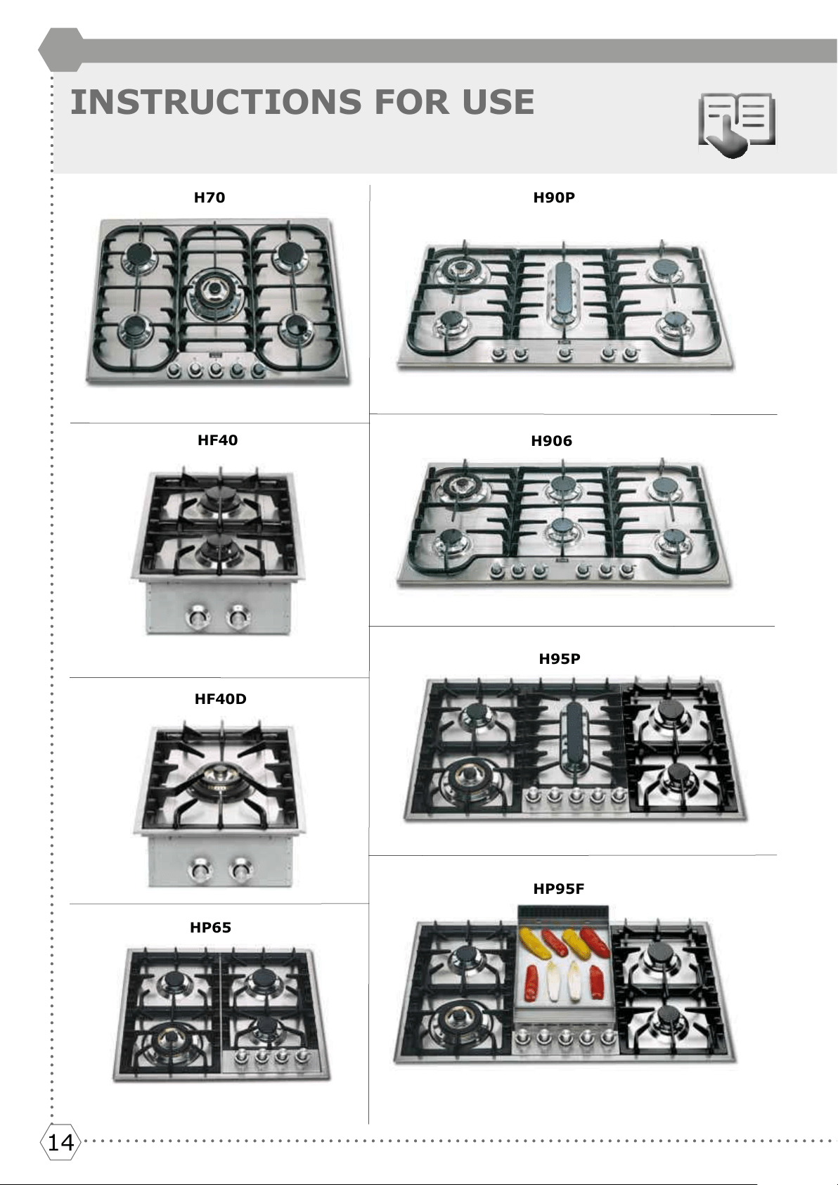
INSTRUCTIONS FOR USE
H70
HF40
HF40D
H90P
H906
H95P
HP95F
HP65
15151515151515
U
S
E
R
GB
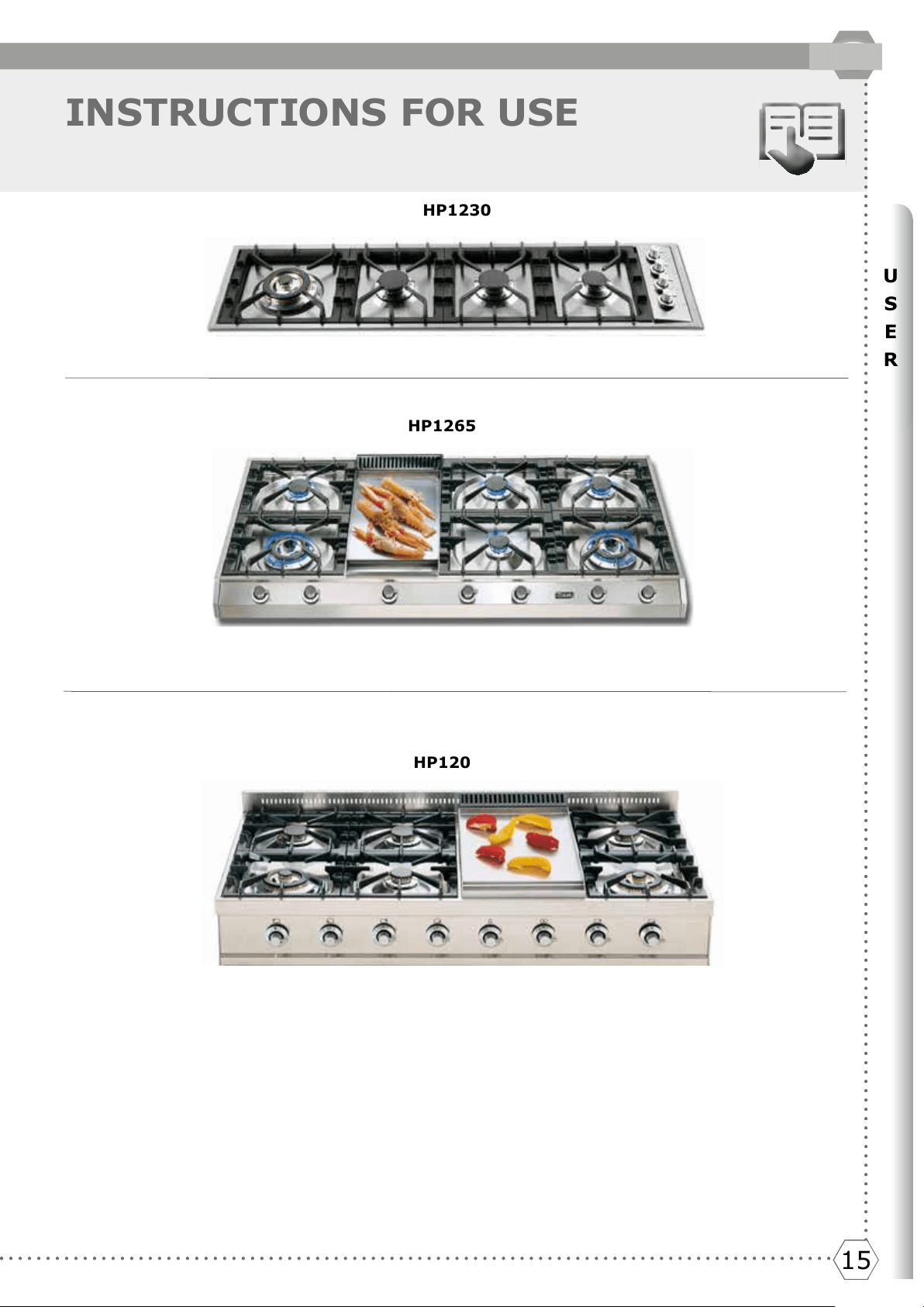
INSTRUCTIONS FOR USE
HP1230
HP120
HP1265
Del et e
HCB60 (1 x Dual Wok, 1 x Large, 2 x Medium)
HCB70 (1 x Wok, 2 x Large, 2 x Medium)
HCB70SD (1 x Dual Wok, 2 x Large, 2 x Medium)
HCB90CC (2 x Woks, 1 x Large, 2 x Medium)
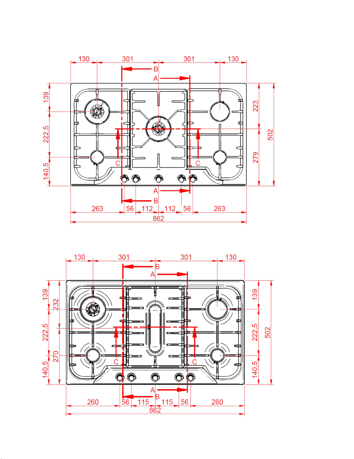
HCB90CD (1 x Dual Wok, 1 x wok, 1 x Large, 2 x Medium)
HCB90PC (1 x Wok, 1 x Large, 2 x Medium, 1 x Fish)
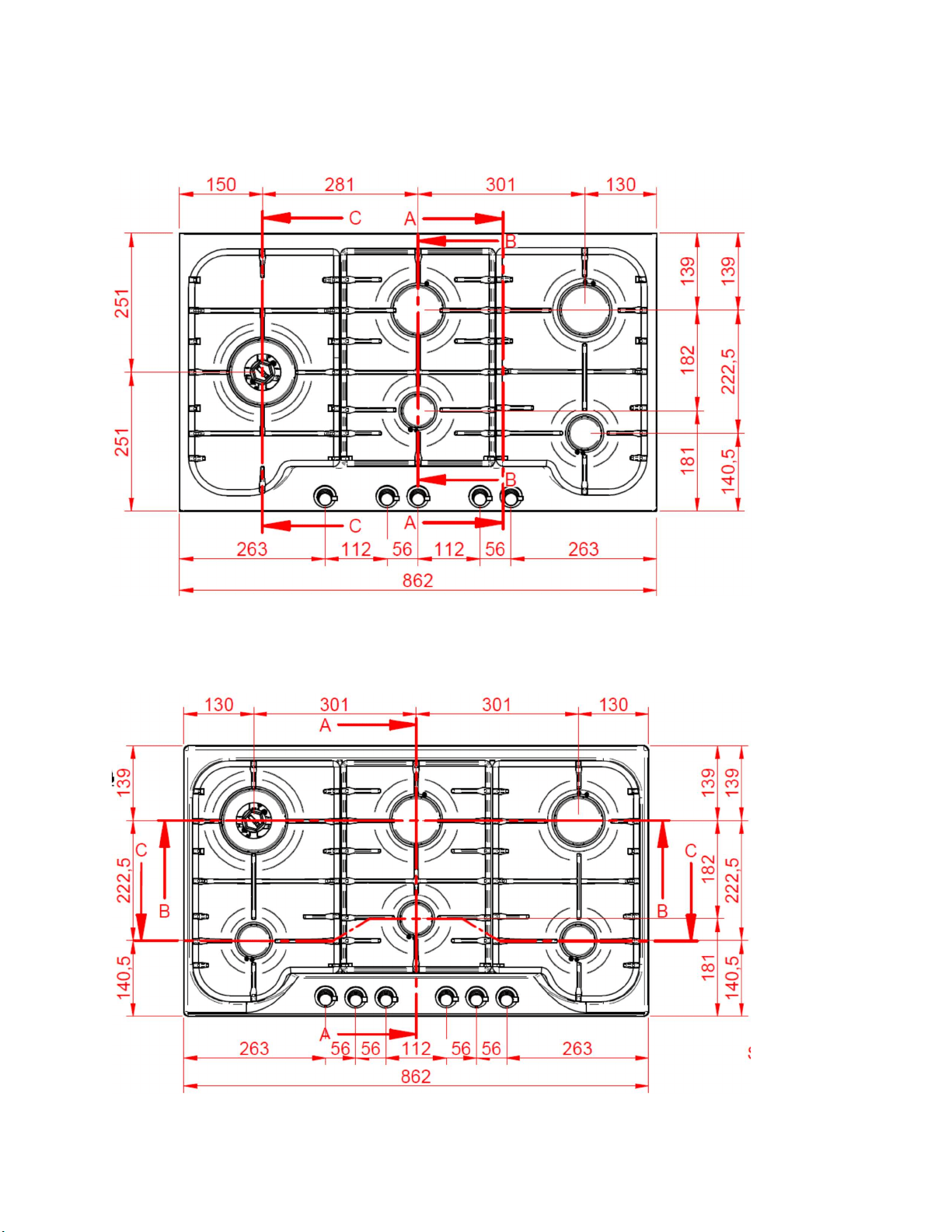
HCB90SD (1 x Dual Wok, 2 x Large, 2 x Medium)
HCB906 (1 x Dual Wok, 2 x Large, 3 x Medium)
1616
INSTRUCTIONS FOR USE
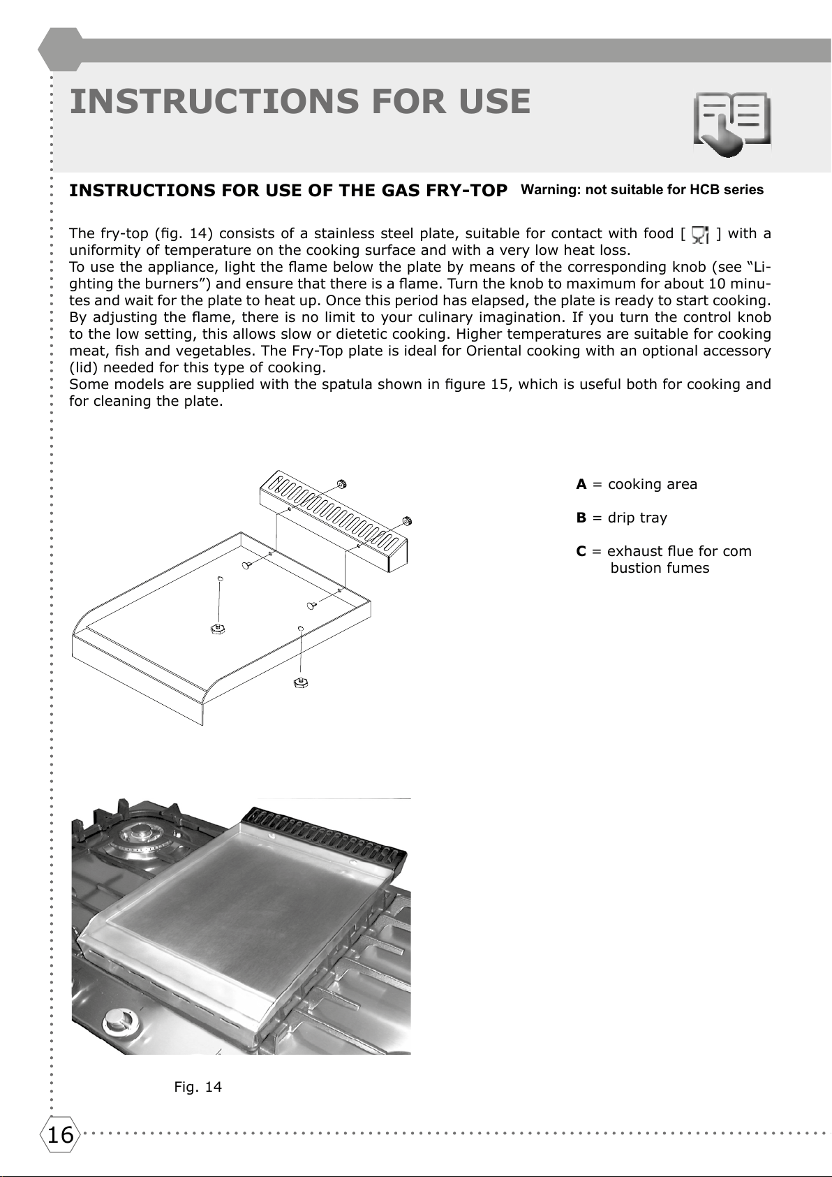
INSTRUCTIONS FOR USE OF THE GAS FRY-TOP
The fry-top (g. 14) consists of a stainless steel plate, suitable for contact with food [ ] with a
uniformity of temperature on the cooking surface and with a very low heat loss.
To use the appliance, light the ame below the plate by means of the corresponding knob (see “Li-
ghting the burners”) and ensure that there is a ame. Turn the knob to maximum for about 10 minu-
tes and wait for the plate to heat up. Once this period has elapsed, the plate is ready to start cooking.
By adjusting the ame, there is no limit to your culinary imagination. If you turn the control knob
to the low setting, this allows slow or dietetic cooking. Higher temperatures are suitable for cooking
meat, sh and vegetables. The Fry-Top plate is ideal for Oriental cooking with an optional accessory
(lid) needed for this type of cooking.
Some models are supplied with the spatula shown in gure 15, which is useful both for cooking and
for cleaning the plate.
A = cooking area
B = drip tray
C = exhaust ue for com
bustion fumes
Fig. 14
Warning: not suitable for HCB series
17171717171717
U
S
E
R
GB
INSTRUCTIONS FOR USE
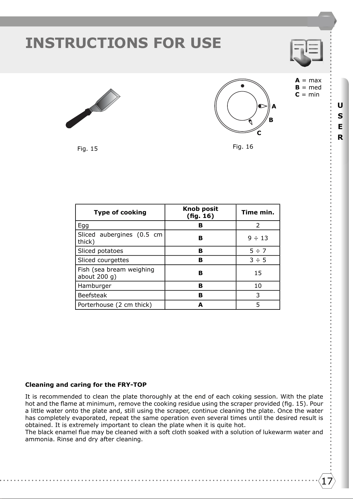
Fig. 15
A
B
C
Type of cooking
Knob posit
(g. 16)
Time min.
Egg B 2
Sliced aubergines (0.5 cm
thick)
B 9 ÷ 13
Sliced potatoes B 5 ÷ 7
Sliced courgettes B 3 ÷ 5
Fish (sea bream weighing
about 200 g)
B 15
Hamburger B 10
Beefsteak B 3
Porterhouse (2 cm thick) A 5
A = max
B = med
C = min
Cleaning and caring for the FRY-TOP
It is recommended to clean the plate thoroughly at the end of each coking session. With the plate
hot and the ame at minimum, remove the cooking residue using the scraper provided (g. 15). Pour
a little water onto the plate and, still using the scraper, continue cleaning the plate. Once the water
has completely evaporated, repeat the same operation even several times until the desired result is
obtained. It is extremely important to clean the plate when it is quite hot.
The black enamel ue may be cleaned with a soft cloth soaked with a solution of lukewarm water and
ammonia. Rinse and dry after cleaning.
Fig. 16
Del et e
1818
INSTRUCTIONS FOR USE
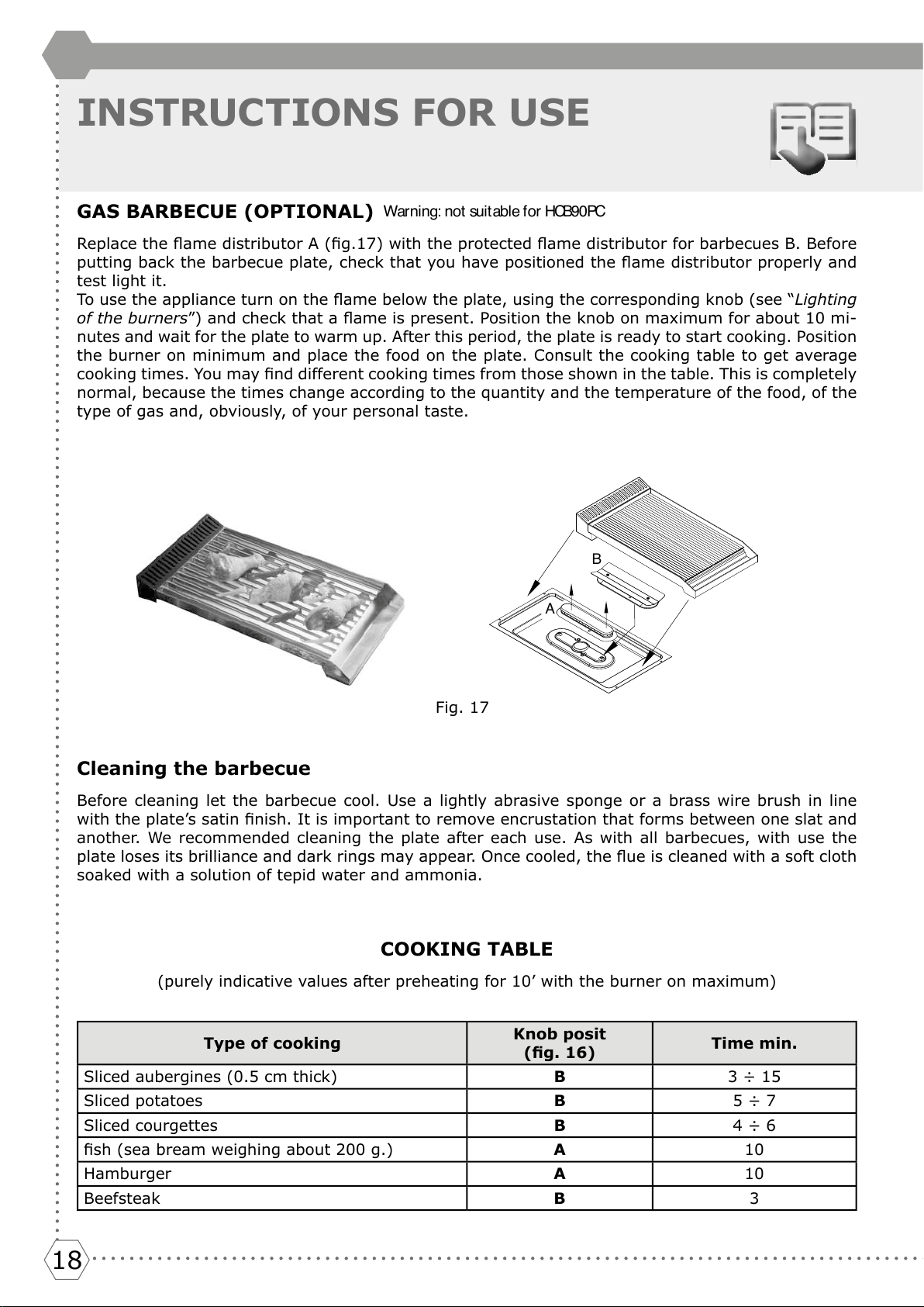
GAS BARBECUE (OPTIONAL)
Replace the ame distributor A (g.17) with the protected ame distributor for barbecues B. Before
putting back the barbecue plate, check that you have positioned the ame distributor properly and
test light it.
To use the appliance turn on the ame below the plate, using the corresponding knob (see “Lighting
of the burners”) and check that a ame is present. Position the knob on maximum for about 10 mi-
nutes and wait for the plate to warm up. After this period, the plate is ready to start cooking. Position
the burner on minimum and place the food on the plate. Consult the cooking table to get average
cooking times. You may nd different cooking times from those shown in the table. This is completely
normal, because the times change according to the quantity and the temperature of the food, of the
type of gas and, obviously, of your personal taste.
B
A
Cleaning the barbecue
Before cleaning let the barbecue cool. Use a lightly abrasive sponge or a brass wire brush in line
with the plate’s satin nish. It is important to remove encrustation that forms between one slat and
another. We recommended cleaning the plate after each use. As with all barbecues, with use the
plate loses its brilliance and dark rings may appear. Once cooled, the ue is cleaned with a soft cloth
soaked with a solution of tepid water and ammonia.
Fig. 17
COOKING TABLE
(purely indicative values after preheating for 10’ with the burner on maximum)
Type of cooking
Knob posit
(g. 16)
Time min.
Sliced aubergines (0.5 cm thick) B 3 ÷ 15
Sliced potatoes B 5 ÷ 7
Sliced courgettes B 4 ÷ 6
sh (sea bream weighing about 200 g.) A 10
Hamburger A 10
Beefsteak B 3
Warning: not suit able for HCB90PC
19191919191919
U
S
E
R
GB
INSTRUCTIONS FOR USE
ELECTRIC GRILL – BARBECUE
This appliance offers you a new cooking method, making it possible to grill meat and sh without fat
and oil for short periods of time inside the home. There is a tray with lava stones under the heating
element. This enables you to have a steady temperature (250°C) and the absorption of fat without
smell and vapours. The grille, tray and lava stones are removable for cleaning. Before plugging in the
appliance put all the parts in their place, place the food on the grill and turn on the appliance using
the adjuster (g.18). Turn the knob to the desired position between 1 and 12; at this point a light
indicates that the appliance is working. To switch off the appliance put the knob on position 0 (the
warning light switches off).
To grill, we recommend pre-heating the grill element for about 6 min. in position 12.
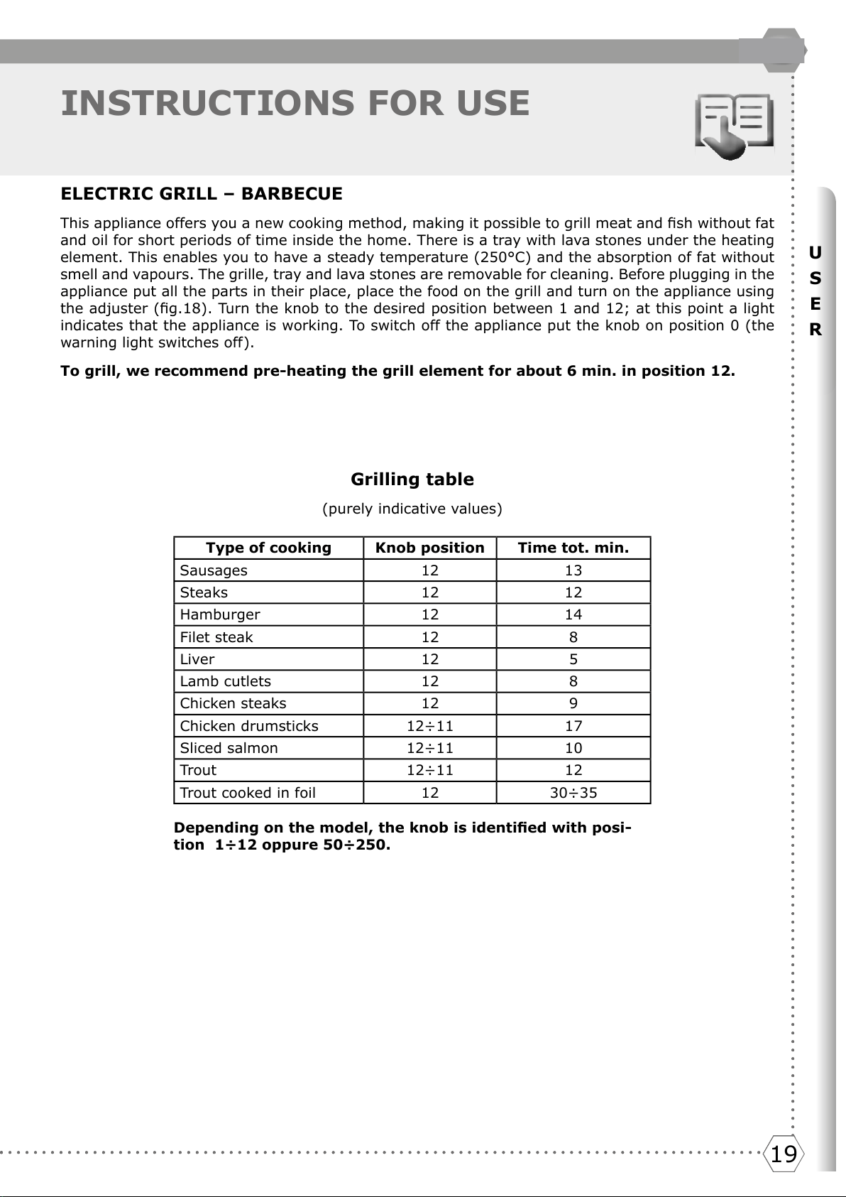
Grilling table
(purely indicative values)
Type of cooking Knob position Time tot. min.
Sausages 12 13
Steaks 12 12
Hamburger 12 14
Filet steak 12 8
Liver 12 5
Lamb cutlets 12 8
Chicken steaks 12 9
Chicken drumsticks 12÷11 17
Sliced salmon 12÷11 10
Trout 12÷11 12
Trout cooked in foil 12 30÷35
Depending on the model, the knob is identied with posi-
tion 1÷12 oppure 50÷250.
Del et e
2020
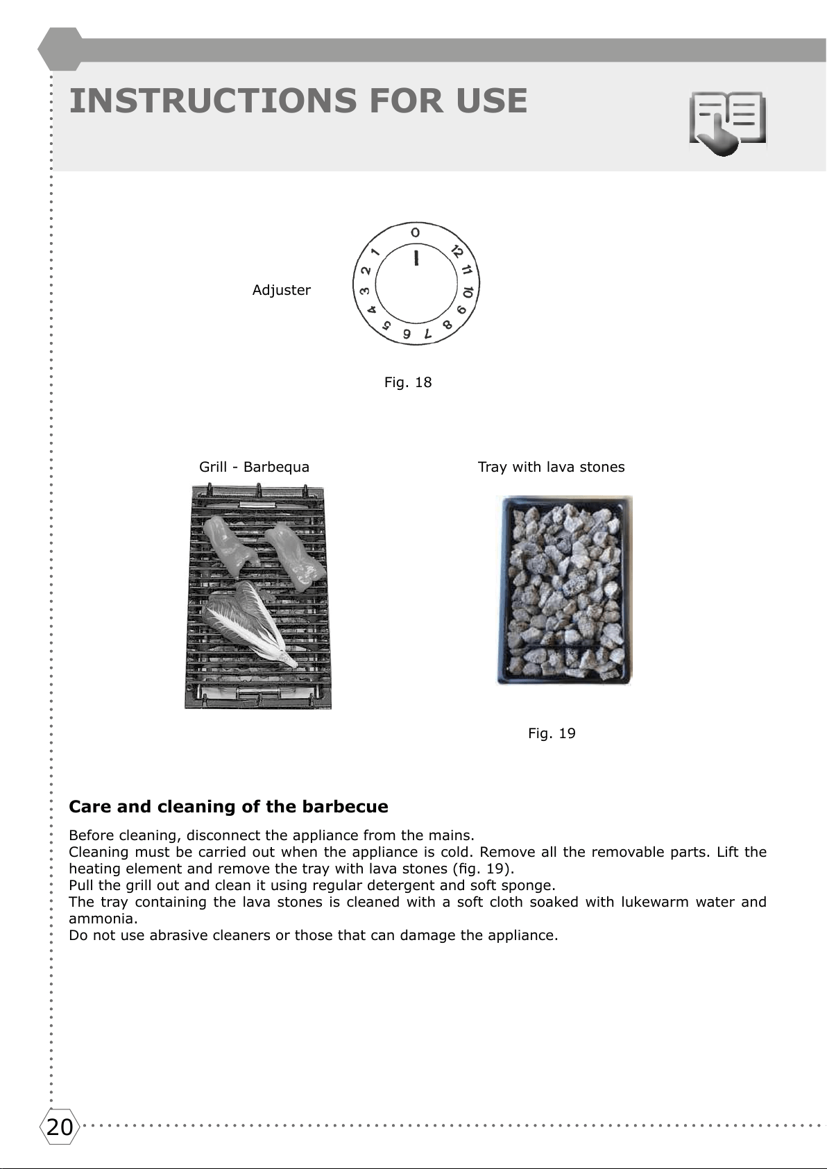
Fig. 19
Grill - Barbequa
Care and cleaning of the barbecue
Before cleaning, disconnect the appliance from the mains.
Cleaning must be carried out when the appliance is cold. Remove all the removable parts. Lift the
heating element and remove the tray with lava stones (g. 19).
Pull the grill out and clean it using regular detergent and soft sponge.
The tray containing the lava stones is cleaned with a soft cloth soaked with lukewarm water and
ammonia.
Do not use abrasive cleaners or those that can damage the appliance.
Tray with lava stones
INSTRUCTIONS FOR USE
Fig. 18
Adjuster
21212121212121
U
S
E
R
GB
CLEANING AND MAINTENANCE
CLEANING THE APPLIANCE
Before any type of cleaning, disconnect the appliance from the mains and shut off the appliance’s gas
tap. Cleaning the worktop: only clean the hob once cold. The burner cups, the enamelled grids, the
enamelled covers and the ame distributors must be cleaned periodically using tepid soapy water,
rinsed and well dried. Any spilt liquid from the pans must always be removed with a rag. Cleaning the
enamelled parts: it is necessary to clean the enamelled parts frequently with soapy water to main-
tain their characteristics. Never use abrasive powders or metal pads. Avoid leaving acidic or alkaline
substances on the enamelled parts (vinegar, lemon juice, salt, tomato juice etc..) and washing when
the enamelled parts are still hot.
Cleaning of the stainless steel parts:
Clean the parts with tepid water and non-corrosive liquid detergent and then dry them with a soft
cloth or in microbre. The brilliance is maintained through periodic cleaning with commercially avai-
lable special products. Never use abrasive powders.
Food stains or residues.
Food stains or residues.
Absolutely avoid using steel sponges and sharp scrapers to not damage the surfaces. Use normal
products, non-abrasive, possibly with the help of wooden or plastic utensils. Rinse carefully and dry
with a soft rag or with a cloth in microbre. Avoid letting dry inside the appliance sugar based food
remains (for example jam) because they might ruin the appliance’s ename
Cooking hob grills
Extract the grills and clean them in tepid water and non- abrasive detergent. Remove all encrusta-
tions with care. Dry the grills and reposition them on the cooking hob.
The continuous contact of the grills with a ame may cause an alteration of the enamel
over time near the areas exposed to heat. This is completely natural and does not com-
promise this component’s.
Igniters and thermocouples
To function properly, the igniters and thermocouples must always be clean. Check them frequently
and if necessary clean them with a damp rag. Any dried remains must be removed with a toothpick
or a needle.
Flame distributor rings and covers
The ame distributor rings and the covers are extractable to facilitate their cleaning. Wash them in
hot water and non- abrasive detergent. Carefully remove every encrustation and wait until they are
perfectly dry.
In case of malfunction, ensure that the holes of the external ring are always perfectly cle-
an.
ATTENTION: It is not recommended to use the dishwasher to clean grills, ame-spreader
and covers.
Annual service by an aut horised person is r ecommended, or if any of t he f ollowing
condit ions are not iced; incomplet e ignit ion, appreciable yellow t ipping, carbon
deposition, lifting, floating, lighting back or objectionable odour. Contact
1300 MYILVE (694 583) www.ilve.com.au
Del et e
2222
INSTALLATION
Installation instructions
This appliance complies with the following directives
DIRECTIVE EU2002/96/EEC
LOW TENSION DIRECTIVE EEC 2014/35/EU
GAS DIRECTIVE 2009/142/EC
ELECTROMAGNETIC COMPATIBILITY DIRECTIVE 2014/30/EU
REGULATION No. 1935/2004 (contact with foods)
Installation must only be made by qualied personnel in the respect of regulations for permanently
ventilated premises according to UNI 7129 01/02/04 – 7131.
Ventilation of the premises
This appliance is type “A” and not to be joined to a combustion products’ expelling device but must be
installed under a hood or another smoke extraction system in compliance with the rules in force. The
knowledge and consultation of the rules is critical for a qualied installer. As an indication, remember
that the air necessary for burner combustion is 2m3/h for each kW of nominal power installed (see
plate). If the appliance is used intensively and for a prolonged time, supplementary ventilation may
be necessary; in this case open a window or increase the power of the mechanical extractor hood.
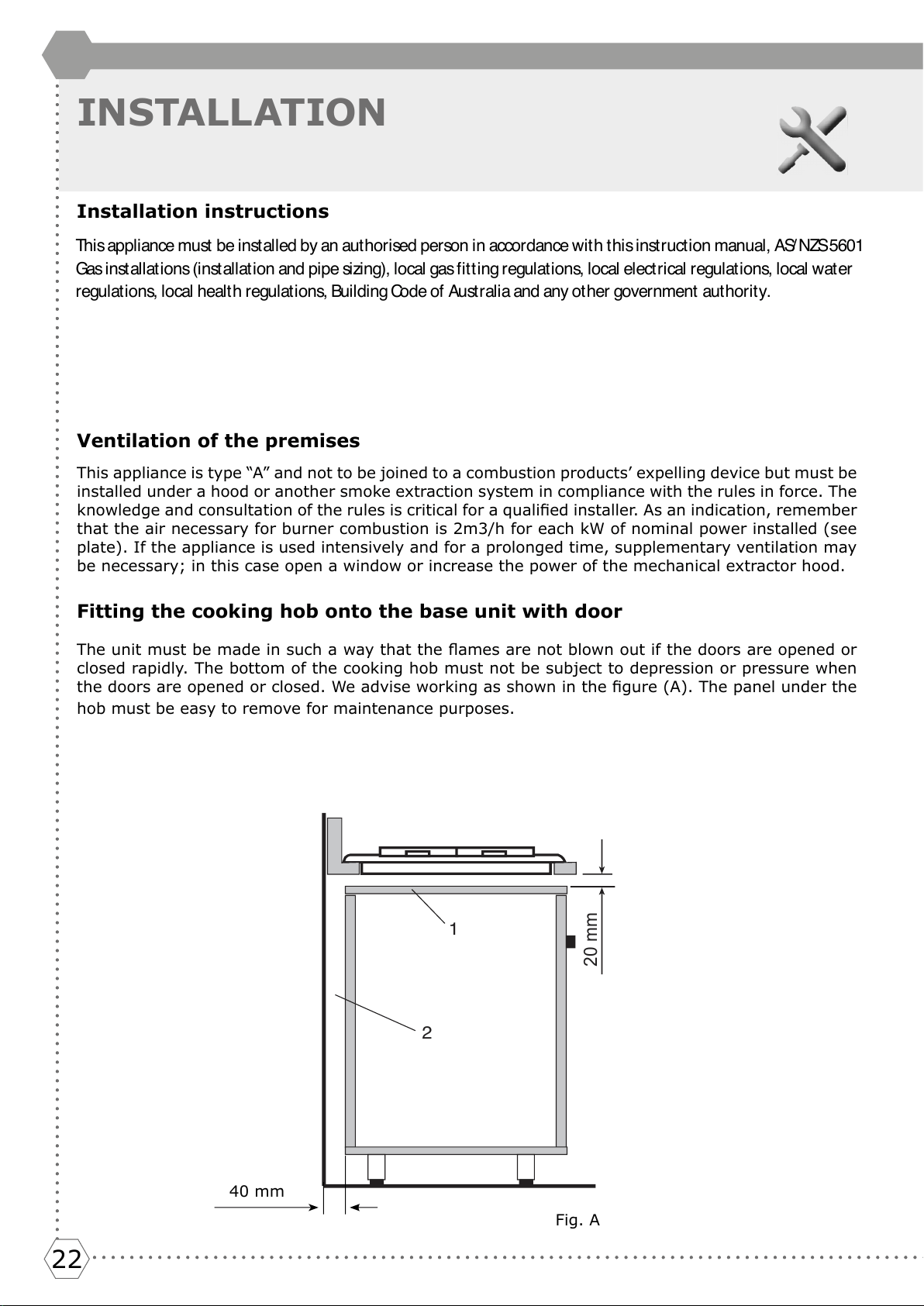
Fitting the cooking hob onto the base unit with door
The unit must be made in such a way that the ames are not blown out if the doors are opened or
closed rapidly. The bottom of the cooking hob must not be subject to depression or pressure when
the doors are opened or closed. We advise working as shown in the gure (A). The panel under the
hob must be easy to remove for maintenance purposes.
1
20 mm
2
Fig. A
40 mm
Thi s appl iance must be i nst al l ed by an aut hor ised per son i n accor dance w i t h t hi s i nst r uct i on manual , AS/ NZS 5601
Gas i n st al l at i o n s (i n st al l at i o n an d p i p e si zi n g) , l o cal gas f i t t i n g r egu l at i o n s, l o cal el e ct r i cal r egu l at i o n s, l o cal w at er
regulations, local health regulations, Building Code of Australia and any other government authority.
2323
I
N
S
T
A
L
L
E
R
23
GB
INSTALLATION
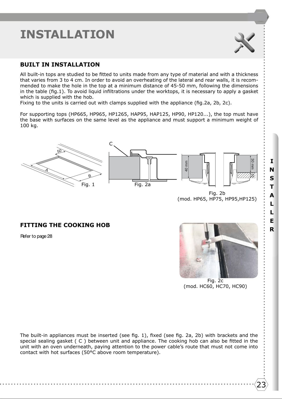
BUILT IN INSTALLATION
All built-in tops are studied to be tted to units made from any type of material and with a thickness
that varies from 3 to 4 cm. In order to avoid an overheating of the lateral and rear walls, it is recom-
mended to make the hole in the top at a minimum distance of 45-50 mm, following the dimensions
in the table (g.1). To avoid liquid inltrations under the worktops, it is necessary to apply a gasket
which is supplied with the hob.
Fixing to the units is carried out with clamps supplied with the appliance (g.2a, 2b, 2c).
For supporting tops (HP665, HP965, HP1265, HAP95, HAP125, HP90, HP120...), the top must have
the base with surfaces on the same level as the appliance and must support a minimum weight of
100 kg.
40 mm
30 mm
10
50
B
A
Fig. 1 Fig. 2a
Fig. 2b
(mod. HP65, HP75, HP95,HP125)
Fig. 2c
(mod. HC60, HC70, HC90)
FITTING THE COOKING HOB
Our appliances can be tted as:
- freestanding, Class 1
- tted between units, Class 2/1
- built-in into units, Class 3
The minimum distances from the furniture must be:
- between top and overhead hood 650 mm
- between top and overhead cabinet 700 mm
- between top and back wall 50 mm
- between top and overhead side wall 50 mm
- between top and lower wall 20 mm
- the built-in top tted onto a base unit with door must be installed according to gure A
- the cooking hobs for supported appliances must support a weight of at least 100 kg
- the furniture must resist at least up to 120°C
- the thickness of the top must be at least 3 cm
The built-in appliances must be inserted (see g. 1), xed (see g. 2a, 2b) with brackets and the
special sealing gasket ( C ) between unit and appliance. The cooking hob can also be tted in the
unit with an oven underneath, paying attention to the power cable’s route that must not come into
contact with hot surfaces (50°C above room temperature).
C
Del et e
Re f e r t o p a g e 2 8
Del et e
2424
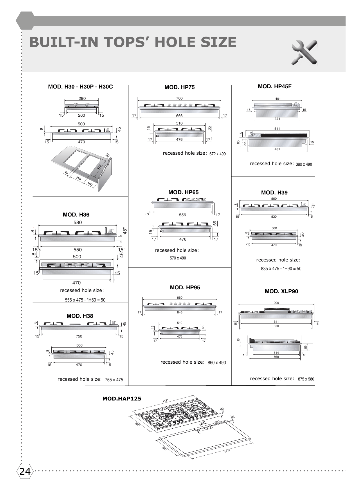
BUILT-IN TOPS’ HOLE SIZE
40
270
160
475
50
15
15
15
15
8
470
500
260
45
290
MOD. H30 - H30P - H30C
15
750
15
45
8
15
470
15
45
8
500
755 x 475
MOD. H38
380 x 490
MOD. HP45F
15
371
511
15
481
15
85
15
15
401
672 x 490
MOD. HP75
700
17 17
15
65
47617 17
666
510
556
15
65
476
17 17
17 17
MOD. HP65
570 x 490
15
470
15
45*
8
500
15
550
15
45*
8
580
MOD. H36
555 x 475 - *H60 = 50
15
830
15
45*
8
860
15
470
15
45*
8
500
835 x 475 - *H90 = 50
MOD. H39
846
17 17
15
65
476
17 17
880
510
MOD. HP95
860 x 490
MOD. XLP90
568
16 16
16
85
514
870
15 15
900
841
875 x 580
65
1
3
0
5
0
5
2
0
1
1
7
1
1
1
7
1
5
2
0
1
5
2
8
0
MOD.HAP125
recessed hole size:
recessed hole size:
recessed hole size:
recessed hole size:
recessed hole size:
recessed hole size:
recessed hole size:
recessed hole size:
2525
I
N
S
T
A
L
L
E
R
25
GB
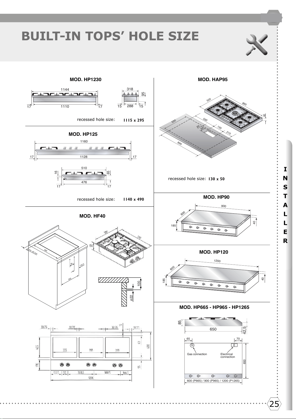
BUILT-IN TOPS’ HOLE SIZE
MOD. HP1230
1115 x 295
17 17
1110
1144
15 15
95
288
318
MOD. HP125
16
65
476
17 17
510
1128
17 17
1160
1140 x 490
06
520
890
130 x 50
520
890
20
50
550
130
210
MOD. HAP95
MOD. HF40
100
ø22
min. 40 mm
485
132,5
355
90
70
650
600 (P665) / 900 (P965) / 1200 (P1265)
65
Electrical
connection
Gas connection
G
E
MOD. HP665 - HP965 - HP1265
MOD. HP90
MOD. HP120
650
42,5
85
900
600
185
04
1200
600
581
04
recessed hole size:
recessed hole size:
recessed hole size:
Del et e
2626
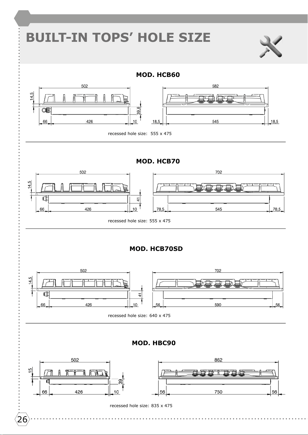
BUILT-IN TOPS’ HOLE SIZE
recessed hole size: 555 x 475
recessed hole size:
555 x 475
recessed hole size: 640 x 475
recessed hole size:
835 x 475
MOD. HCB60
MOD. HCB70
MOD. HCB70SD
MOD. HBC90
2727
I
N
S
T
A
L
L
E
R
27
GB
ELECTRIC CONNECTION
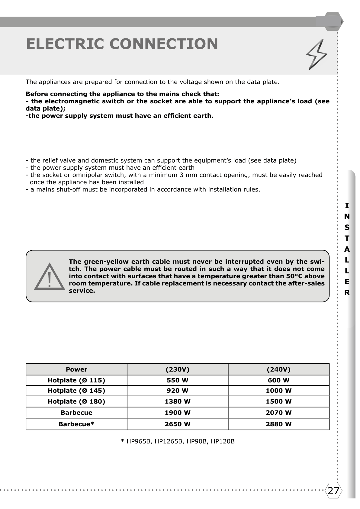
The appliances are prepared for connection to the voltage shown on the data plate.
Before connecting the appliance to the mains check that:
- the electromagnetic switch or the socket are able to support the appliance’s load (see
data plate);
-the power supply system must have an efcient earth.
The appliance is supplied with a cable but without a plug: the connection must be made taking into
account that the green-yellow cable is the earth conductor and it must never be interrupted.
or direct connection to the mains, it is necessary that:
- the relief valve and domestic system can support the equipment’s load (see data plate)
- the power supply system must have an efcient earth
- the socket or omnipolar switch, with a minimum 3 mm contact opening, must be easily reached
once the appliance has been installed
- a mains shut-off must be incorporated in accordance with installation rules.
The green-yellow earth cable must never be interrupted even by the swi-
tch. The power cable must be routed in such a way that it does not come
into contact with surfaces that have a temperature greater than 50°C above
room temperature. If cable replacement is necessary contact the after-sales
service.
Power (230V) (240V)
Hotplate (Ø 115) 550 W 600 W
Hotplate (Ø 145) 920 W 1000 W
Hotplate (Ø 180) 1380 W 1500 W
Barbecue 1900 W 2070 W
Barbecue* 2650 W 2880 W
* HP965B, HP1265B, HP90B, HP120B
Del et e
Delet e
2828
GAS CONNECTION
AND TRANSFORMATION
GAS CONNECTION
(UNI CIG 7129/7131)
The appliances must be attached to the gas pipeline with rigid or exible metal pipes (maximum
length 2 metres) suitable for gas appliances. The connection pipes and their maximum length must
comply with the applicable standards, replaced before the expiry date (if indicated on the pipe) and
connected to the appliance by a coupling:
a) directly on the connection ISO R228 (with ISO R228 sealing gasket), if the pipe’s route allows it
g. 3
b) •if the connection is to be directed (right-left-low), the supplied connection (g. 4a - g. 4b) must
be used.
•for the seal between the pipe and the ramp gas use the gasket (ISO R228) g. 4a
•for the seal on the thread (ISO R7) it is necessary to use conical connections on the thread (g.
4b)
•to improve the seal, a mastic suitable for GAS can be used.
When the gas is drawn from a cylinder, the appliance, supplied with a pressure regulator compliant
with standard UNI-CIG 7432, must be connected: with exible stainless steel pipes along the wall,
according to standard UNI-CIG 9891, with 2 metres maximum extension and sealing gasket accor-
ding to standard UNI 9264.
PRECAUTIONS FOR USING THE PRODUCT WITH GPL GAS:
The gas taps tted in your kitchen must work with liquid gas of controlled quality, supplied at the
proper nominal pressure. This pressure must be guaranteed by a special certied pressure regulator.
The use of gas coming from uncertied sources and/or the improper use of the GPL cylinder as well
as the relative regulator, can invalidate the product’s guarantee. It is especially necessary to avoid
all the situations that could pollute the gas with residues and impurities that, when introduced into
the gas circuit, can irreparably damage the control components such as taps and thermostats. It is
recommended to:
• use only GPL cylinders coming from ofcial retailers and authorised by the various manufacturers
• use the cylinders until empty without inclining or overturning them
• carry out regular cleaning of the lter at the pressure regulator inlet
BE CAREFUL:
When the connection is made, it is recommended to check the connections’ seal with special foams
(NO FLAMES).
IMPORTANT:
Periodically check the gas connection pipe’s good condition and replace it when there are signs of
anomalies.
Thi s appl iance i s sui t abl e f or connect i on w it h r i gi d pi pe or f l exi bl e hose. The i sol at i ng manual shut -of f val ve
connect ion point must be accessible when t he appliance is inst alled. The flexible hose assembly must be cert if ied
to AS/NZS 1869 class B or D, be of appropriate internal diameter for the total gas consumption, be kept as short
as possible (not exceeding 1200mm), must not be in cont act wit h t he floor or any hot or sharp surfaces. The hose
assembly must not be subject t o st rain, abrasion, kinking or deformat ion.
Nat ural Gas: t he supplied regulat or must be fit t ed t o t he appliance inlet connect ion. Gas pressure must be
adjusted t o 1.0 kPa when approximat ely 50% of t he burners are on high f lame, t he appliance t est point is locat ed
on the regulator.
ULPG: t he supplied t est point adapt or must be f it t ed t o t he appliance inlet connect ion. Gas pressure must be
adjusted t o 2.75 kPa, t he appliance t est point is locat ed on t he t est point adapt or.
Gas l eak age an d op er at i o n o f t h e ap pl i an ce mu st be t e st e d b y t h e i n st al l er b ef o r e l eav i n g. Ch eck b ur n er f l am es
are blue in colour, st able and complet ely ignit e at bot h high and low flame set t ings wit h no appreciable yellow
tipping, carbon deposition, lifting, floating, lighting back or objectionable odour. Test burners individually and in
combinat ion, When sat isfied wit h t he operat ion of t he cooker, please instruct t he user on t he correct met hod of
operation.
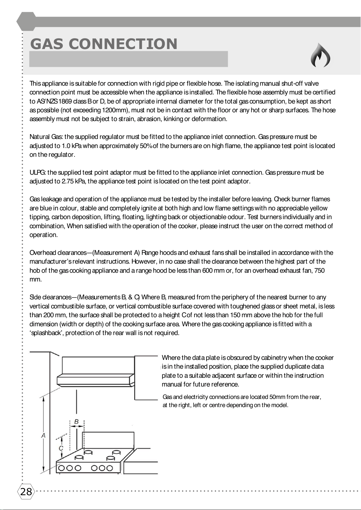
Over head clear ances—(M easur ement A) Range hoods and exhaust f ans shal l be i nst al l ed i n accor dance wi t h t he
manufacturer’s relevant instructions. However, in no case shall the clearance between the highest part of the
hob of the gas cooking appliance and a range hood be less than 600 mm or, for an overhead exhaust fan, 750
mm.
Si d e c l e a r a n c e s— ( M e a su r e m e n t s B, & C) W h e r e B , m e a su r e d f r o m t h e p e r i p h e r y o f t h e n e a r e st b u r n e r t o a n y
vertical combustible surface, or vertical combustible surface covered with toughened glass or sheet metal, is less
than 200 mm, the surface shall be protected to a height C of not less than 150 mm above the hob for the full
dimension (width or depth) of the cooking surface area. Where the gas cooking appliance is fitted with a
‘splashback’, protection of the rear wall is not required.
Where the data plate is obscured by cabinet ry when the cooker
is in the installed position, place the supplied duplicate data
plate to a suitable adjacent surface or within the instruction
manual for future reference.
Del et e
Gas an d e l ect r i ci t y co n nect i o n s ar e l o cat ed 50m m f r o m t h e r ear ,
at t he right , left or cent re depending on t he model.
2929
I
N
S
T
A
L
L
E
R
29
GB
GAS CONNECTION
AND TRANSFORMATION
Guarnizione
Fig. 3
Guarnizione
Guarnizione
Fig. 4b
Fig. 4a
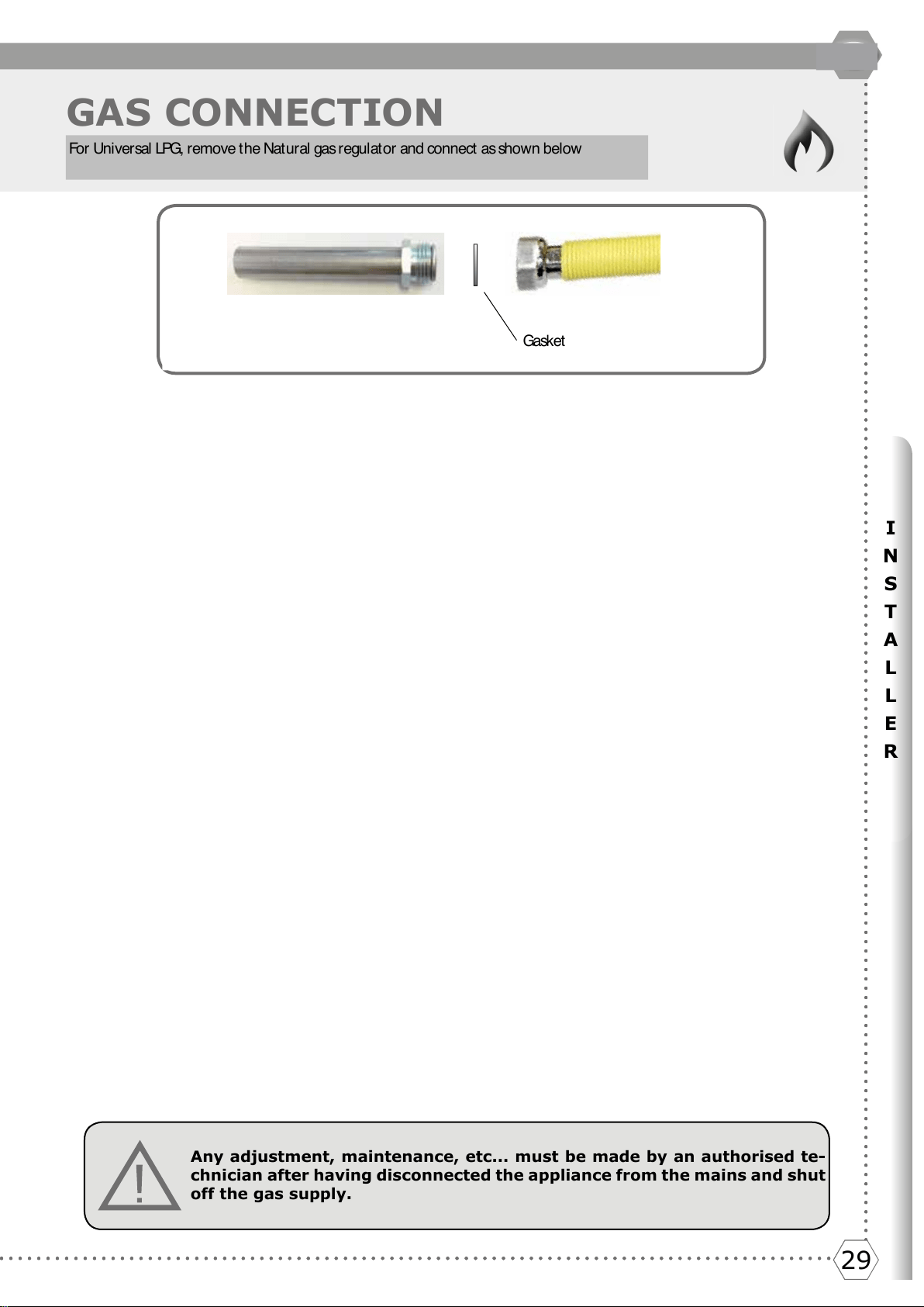
Any adjustment, maintenance, etc... must be made by an authorised te-
chnician after having disconnected the appliance from the mains and shut
off the gas supply.
Raccordo
Raccordo
Del et e
Del et e
.
Gask et
Fo r Un i v er sal LPG, r e m o ve t h e Nat u r al gas r e gu l at o r an d co n n ect as sh o w n b el o w
3030
ADJUSTMENT
The hobs are delivered to operate as indicated on the data plate. If a transformation
should be necessary, proceed as described in the next paragraph.
ADJUSTMENT- ADAPTING TO DIFFERENT TYPES OF GAS
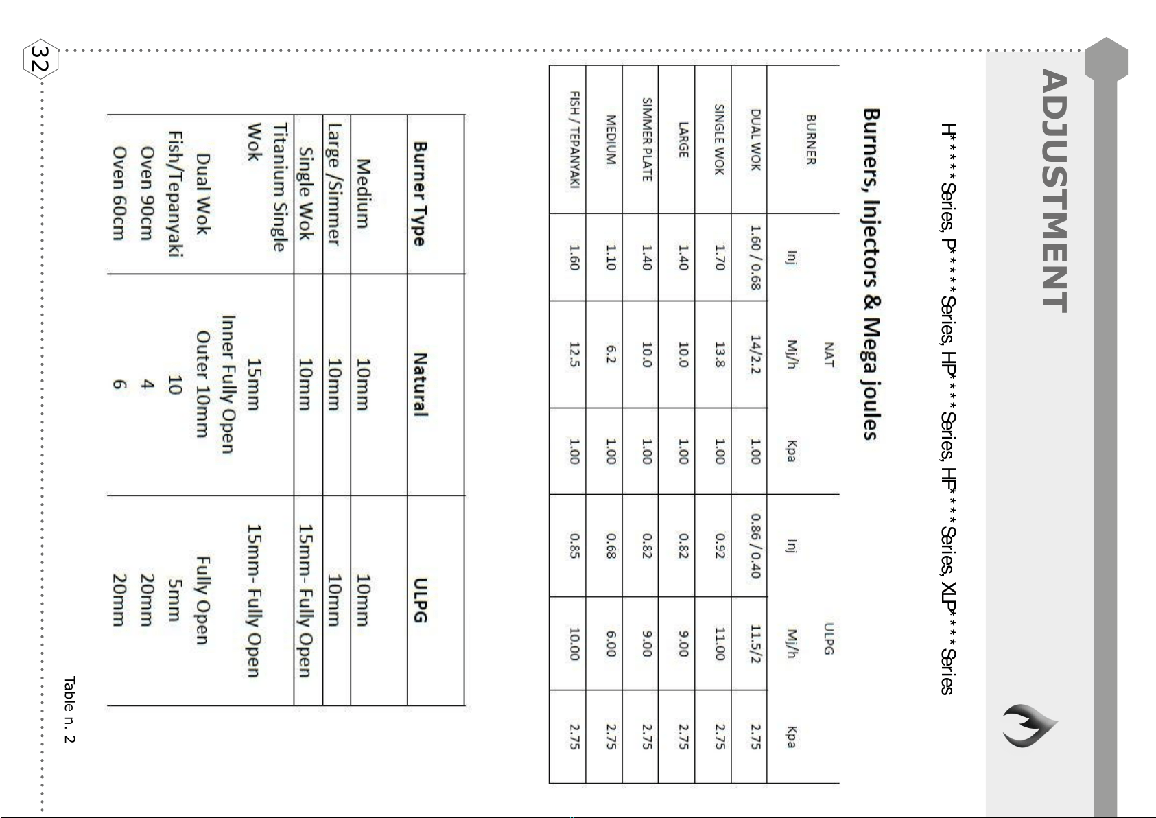
Injector replacement and air adjustment for models: H30 - H360 - H380 - H39 - HF40 - HP45F
- HP65 - HP75 - HP95 - HAP95 - XLP90F- HP1230 - HP125 - HAP125 - HP665 - HP965 - HP1265 -
HP90 - HP120
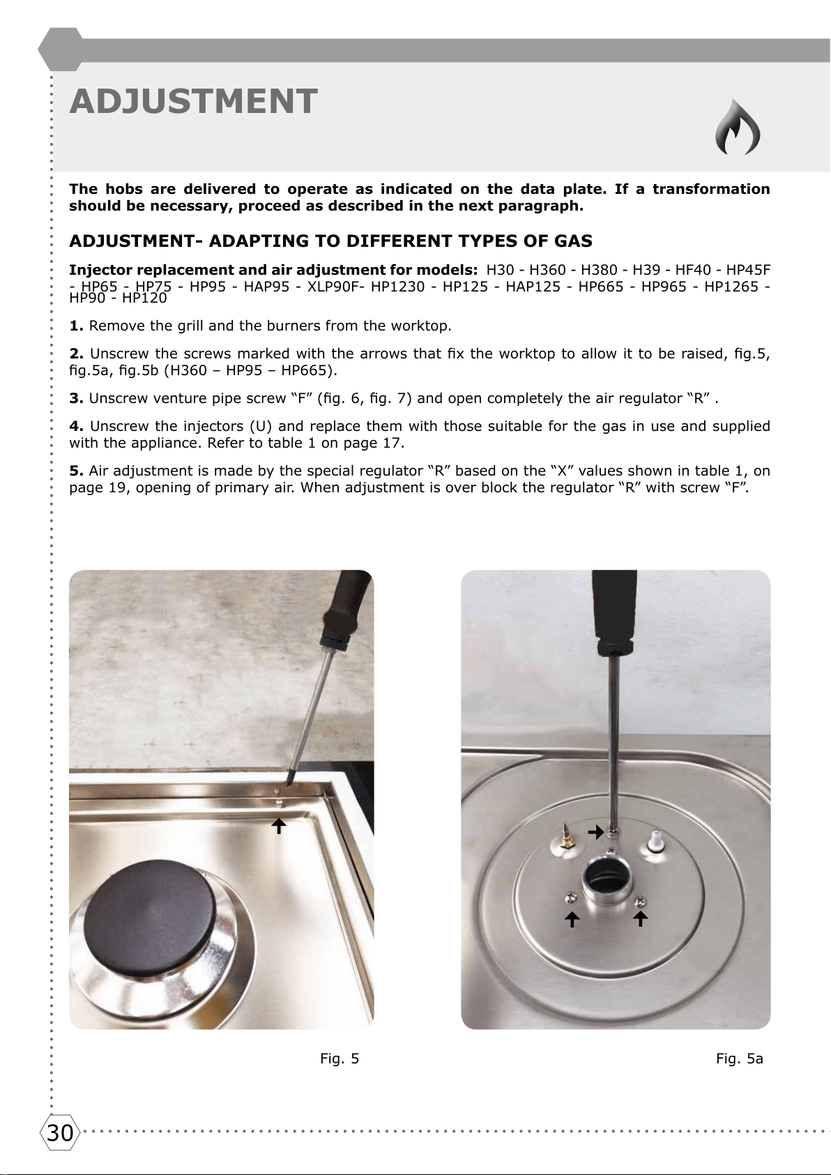
1. Remove the grill and the burners from the worktop.
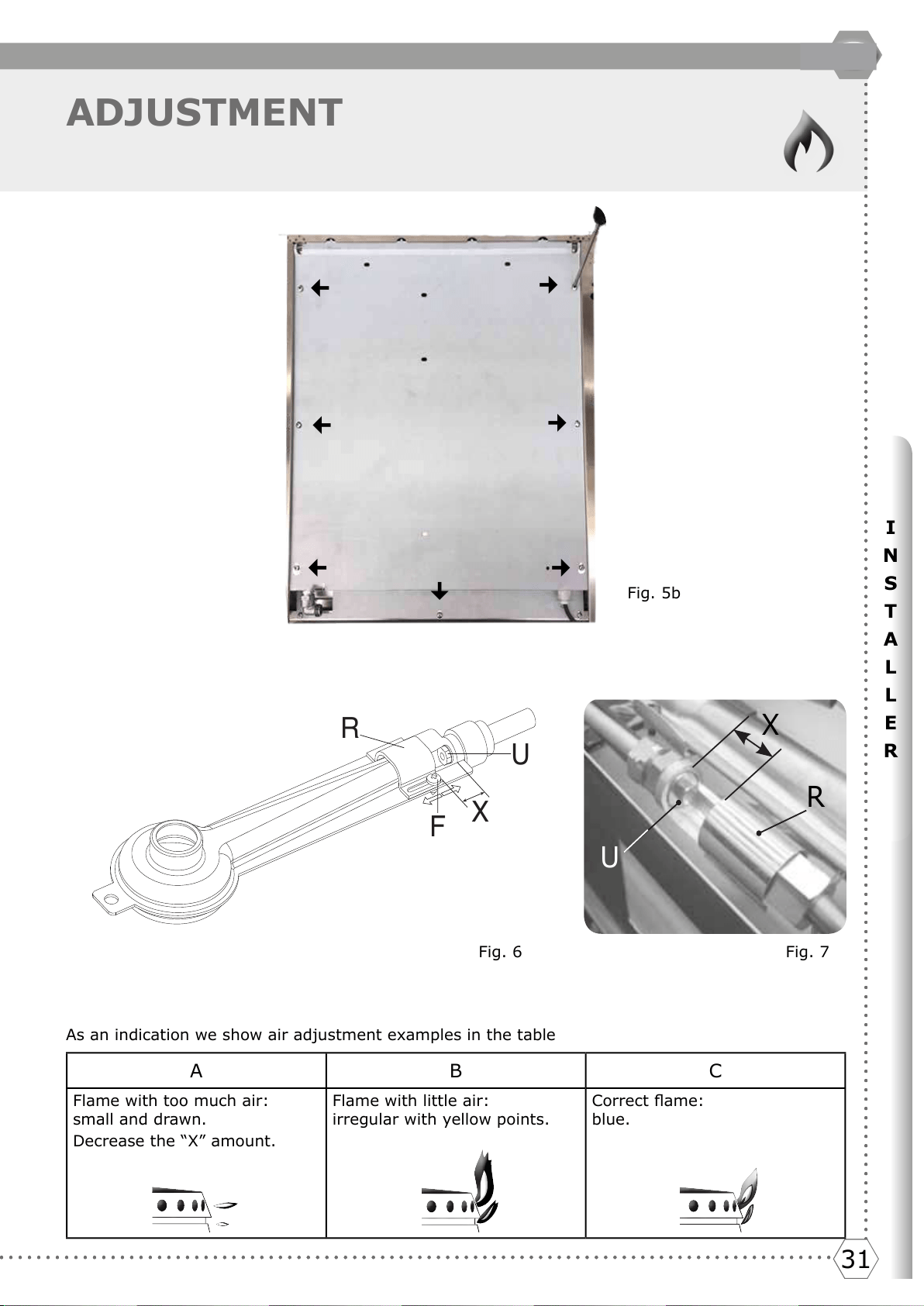
2. Unscrew the screws marked with the arrows that x the worktop to allow it to be raised, g.5,
g.5a, g.5b (H360 – HP95 – HP665).
3. Unscrew venture pipe screw “F” (g. 6, g. 7) and open completely the air regulator “R” .
4. Unscrew the injectors (U) and replace them with those suitable for the gas in use and supplied
with the appliance. Refer to table 1 on page 17.
5. Air adjustment is made by the special regulator “R” based on the “X” values shown in table 1, on
page 19, opening of primary air. When adjustment is over block the regulator “R” with screw “F”.
Fig. 5 Fig. 5a
3131
I
N
S
T
A
L
L
E
R
31
GB
ADJUSTMENT
F
X
R
U
A B C
Flame with too much air:
small and drawn.
Decrease the “X” amount.
Flame with little air:
irregular with yellow points.
Correct ame:
blue.
Fig. 6
As an indication we show air adjustment examples in the table
Fig. 7
X
R
U
Fig. 5b
Del et e
3232
ADJUSTMENT
GAS JETS ADJUSTMENT TABLE
Table n. 2
SR R P C
Qmax
kW
1.80 2.60 3.10
4,30 / 3,40
(3)
Qmax g/
h
131 189 225 313
Qmin
kW
0,40 / 0,51
(1)
/ 0,45
(2)
0,60 / 0,76
(1)
/ 0,66
(2)
1,20 / 1,57
(1)
/ 1,35
(2)
1,70 / 1,80
(4)
/ 2,20
(1)
/ 2,32
(1)(4)
/ 1,90
(2)
/ 2
(2)
Qmin g/h
29 / 37
(1)
/ 33
(2)
44 / 55
(1)
/ 48
(2)
87 / 114
(1)
/ 98
(2)
(4)
124 / 131
(4)
/ 160
(1)
/ 169
(1)(4)
/ 138
(2)
/ 145
(2)(4)
G30/G31 28..30/37 mbar 0.62 0.78 0.82 1.00 0.35 0.92
0,35
(4)
1,00
(4)
G30/G31 50 mbar 0.55 0.68 0.75 0.90 0.33 0.82
0,33
(4)
0,88
(4)
G30 37 mbar 0.62 0.74 0.82 0.92 0.35 0.92
0,35
(4)
0,92
(4)
G20 20 mbar 0.97 1.17 1.30 1.50 0.55 1.40
0,55
(4)
1,50
(4)
G20 25 mbar 0.87 1.10 1.17 1.35 0.55 1.35
0,55
(4)
1,40
(4)
G25 20 mbar 1.05 1.30 1.45 1.65 0.62 1.60
0,62
(4)
1,70
(4)
G25 25 mbar 0.97 1.23 1.35 1.55 0.62 1.50
0,62
(4)
1,60
(4)
G25.3 25 mbar 0.97 1.17 1.30 1.55 0.55 1.50
0,55
(4)
1,60
(4)
G2.350 13 mbar 1.35 1.65
1,85 / 1,80
(4)
2.20 0.78 2.20
0,78
(4)
2,40
(4)
G25.1 25 mbar 1.05 1.25 1.35 1.60 0.62 1.55
0,62
(4)
1,60
(4)
G110 8 mbar 1.90
2,45 / 2,30
(4)
3,00 / 2,60
(4)
3.30 1.10 3.20
1,10
(4)
3,20
(4)
G120 8 mbar 1.75
2,30 / 2,20
(4)
2,60 / 2,40
(4)
3.20 1.05 3.00
1,05
(4)
3,00
(4)
G150.1 8 mbar 1.85 2.40
3,20 / 2,80
(4)
3,30 / 3,20
(4)
1.10 3.30
1,10
(4)
3,00
(4)
G30/G31
0,30 / 0,32
(4)
0,38 / 0,40
(4)
0,56 / 0,52
(4)
0,66 / 0,75
(4)
0.24 0.65
0,27
(4)
0,60
(4)
G20 REG REG REG REG REG REG REG REG
G25 REG REG REG REG REG REG REG REG
G2.350 13 mbar REG REG REG REG REG REG REG REG
G110/G120 REG REG REG REG REG REG REG REG
G30/G31 2.00 6.00 20.00 20.00 20.00 20.00 20.00 20.00
G20 2.00 3.00 3.00 6.00 20.00 4.00 20.00 4.00
G25 2.00 3.00 3.00 4.00 20.00 4.00 20.00 4.00
G25.3 0.00 1.00 0.00 3.00 2.00 3.00 2.00 3.00
G2.350 13 mbar 0.00 3.00 5.00 5.00 20.00 4.00 20.00 10.00
G110/G120 0.00 0.00 0.00 3.00 1.00 0.00 1.00 1.00
G150.1 8 mbar 0.00 0.00 0.00 3.00 1.00 10.00 1.00 10.00
(1)=DE AT (2)=PL (3)=G110/G120/G150.1 (4)=RUBINETTO CUCINE
22
27 / 36
(1)
/ 33
(2)
Ø mm
by-pass Ø
mm
X= mm
DUAL DUAL
4,50 / 3,60
(3)
5,00 / 3,60
(3)
0.30
0,37 / 0,50
(1)
/ 0,45
(2)
327 364
H* * * * * Ser ies, P* * * * * Seri es, HP* * * * Seri es, HF* * * * Series, XLP* * * * Seri es
delete
Del et e
3333
I
N
S
T
A
L
L
E
R
33
GB
ADJUSTMENT
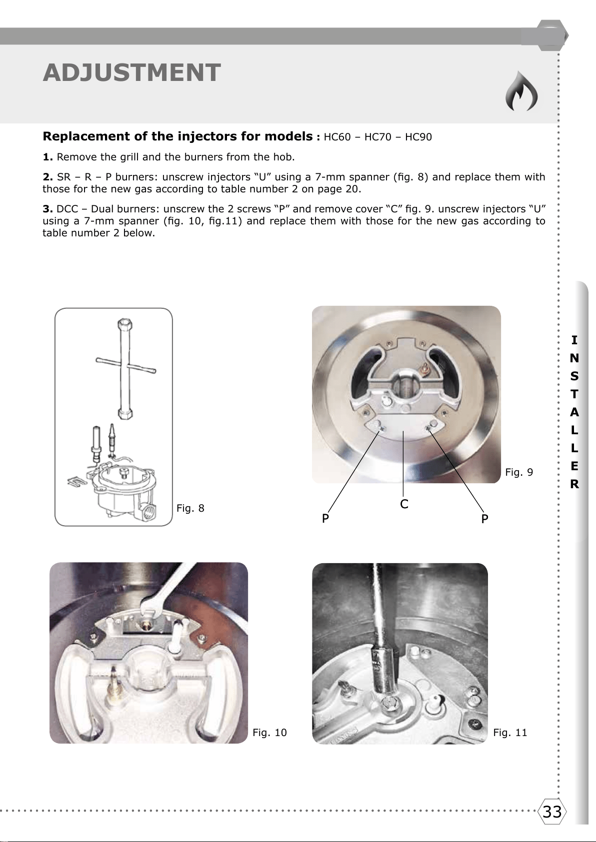
Replacement of the injectors for models : HC60 – HC70 – HC90
1. Remove the grill and the burners from the hob.
2. SR – R – P burners: unscrew injectors “U” using a 7-mm spanner (g. 8) and replace them with
those for the new gas according to table number 2 on page 20.
3. DCC – Dual burners: unscrew the 2 screws “P” and remove cover “C” g. 9. unscrew injectors “U”
using a 7-mm spanner (g. 10, g.11) and replace them with those for the new gas according to
table number 2 below.
Fig. 8
Fig. 9
Fig. 10 Fig. 11
C
P
P
C
P
P
Del et e
3434
ADJUSTMENT
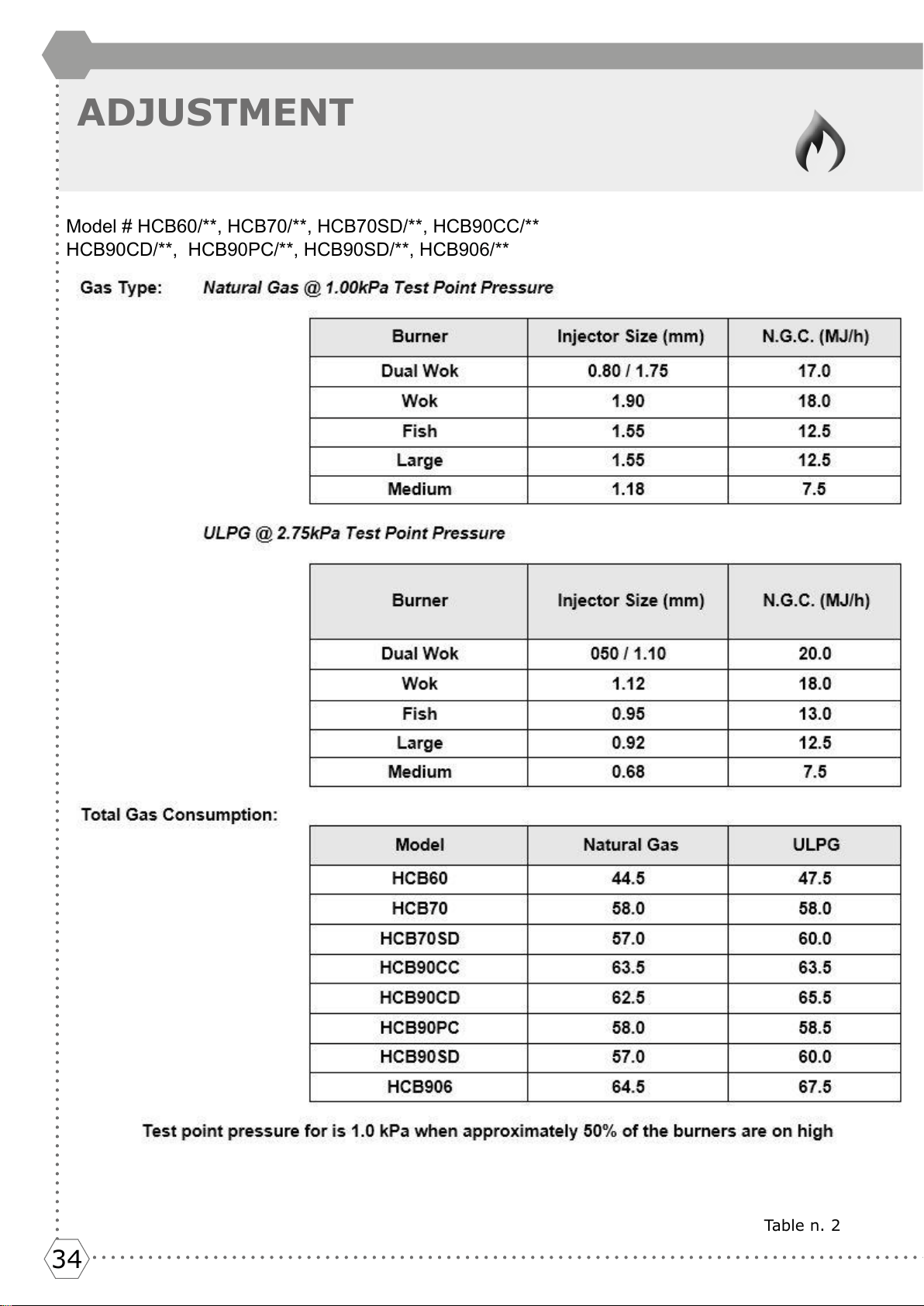
Table n. 2
HCB90CD/**, HCB90PC/**, HCB90SD/**, HCB906/**
Model # HCB60/**, HCB70/**, HCB70SD/**, HCB90CC/**
3535
I
N
S
T
A
L
L
E
R
35
GB
ADJUSTMENT
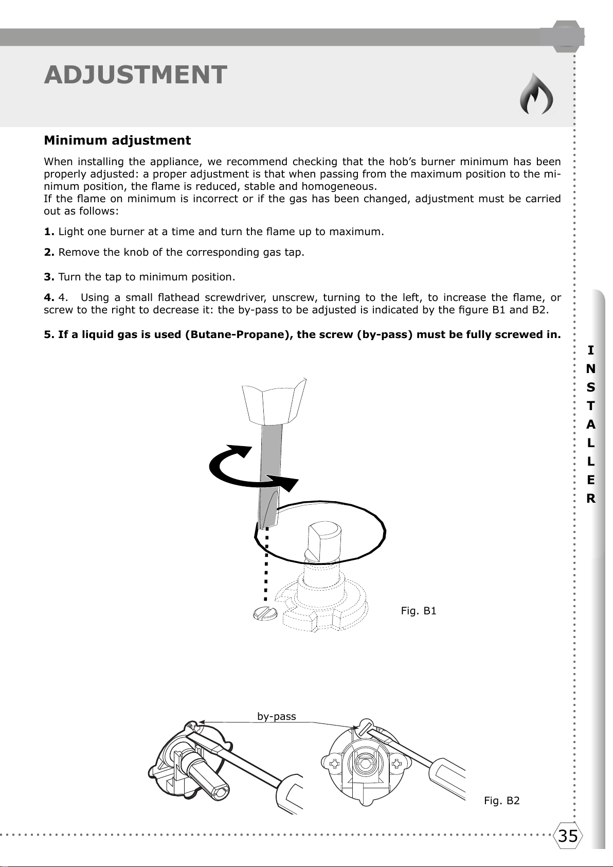
Minimum adjustment
When installing the appliance, we recommend checking that the hob’s burner minimum has been
properly adjusted: a proper adjustment is that when passing from the maximum position to the mi-
nimum position, the ame is reduced, stable and homogeneous.
If the ame on minimum is incorrect or if the gas has been changed, adjustment must be carried
out as follows:
1. Light one burner at a time and turn the ame up to maximum.
2. Remove the knob of the corresponding gas tap.
3. Turn the tap to minimum position.
4. 4. Using a small athead screwdriver, unscrew, turning to the left, to increase the ame, or
screw to the right to decrease it: the by-pass to be adjusted is indicated by the gure B1 and B2.
5. If a liquid gas is used (Butane-Propane), the screw (by-pass) must be fully screwed in.
by-pass
Fig. B2
Fig. B1
Del et e
3636
WIRING DIAGRAMS
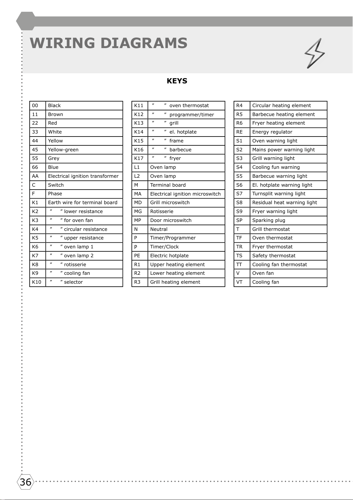
KEYS
00 Black
11 Brown
22 Red
33 White
44 Yellow
45 Yellow-green
55 Grey
66 Blue
AA Electrical ignition transformer
C Switch
F Phase
K1 Earth wire for terminal board
K2 ” ” lower resistance
K3 ” ” for oven fan
K4 ” ” circular resistance
K5 ” ” upper resistance
K6 ” ” oven lamp 1
K7 ” ” oven lamp 2
K8 ” ” rotisserie
K9 ” ” cooling fan
K10 ” ” selector
K11 ” ” oven thermostat
K12
” ” programmer/timer
K13 ” ” grill
K14 ” ” el. hotplate
K15 ” ” frame
K16 ” ” barbecue
K17 ” ” fryer
L1 Oven lamp
L2 Oven lamp
M Terminal board
MA Electrical ignition microswitch
MD Grill microswitch
MG Rotisserie
MP Door microswitch
N Neutral
P Timer/Programmer
P
Timer/Clock
PE Electric hotplate
R1 Upper heating element
R2 Lower heating element
R3 Grill heating element
R4 Circular heating element
R5 Barbecue heating element
R6 Fryer heating element
RE Energy regulator
S1 Oven warning light
S2 Mains power warning light
S3 Grill warning light
S4 Cooling fun warning
S5 Barbecue warning light
S6 El. hotplate warning light
S7 Turnsplit warning light
S8 Residual heat warning light
S9 Fryer warning light
SP Sparking plug
T Grill thermostat
TF Oven thermostat
TR Fryer thermostat
TS Safety thermostat
TT Cooling fan thermostat
V Oven fan
VT Cooling fan
3737
I
N
S
T
A
L
L
E
R
37
GB
WIRING DIAGRAMS
K1
M
66
11
P2
22
P3 5
C
33
S6
PE
N F
2
1
3
4
P1
66
11
P2
P3 5
C
2
1
3
4
P1
1
2
4
3
55
44
33
22
33
PE
1
2
4
3
55
44
33
K14 K15
45
AA
SP
66
MA
MA
MA
MA MA
11
SP
AA
66
11
11
MA
MA
MA
RE
00
S5
MA MA
N F
M
11
66
P2 4
00
P1 2
00
R5
K1 K15 K16
45
§
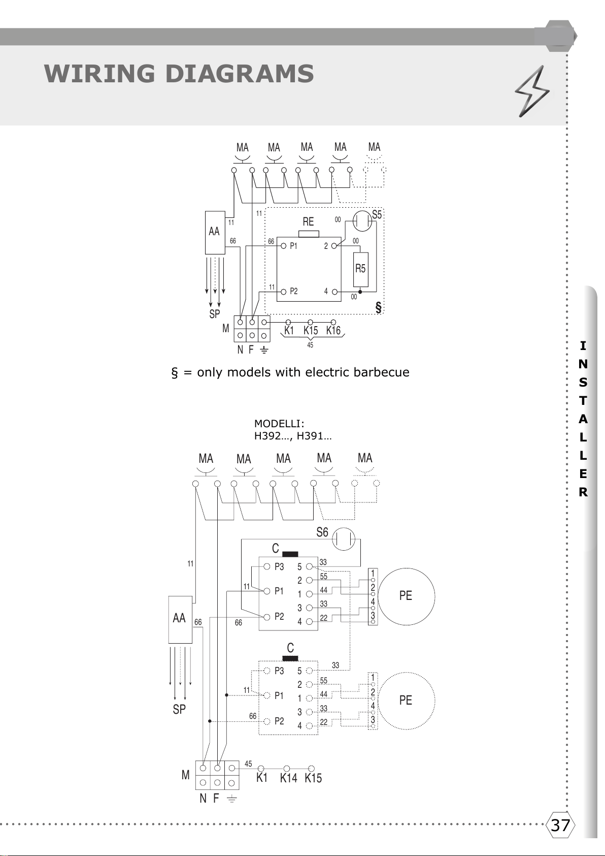
MODELLI:
H392…, H391…
§ = only models with electric barbecue
Del et e
3838
PROBLEM SOLVING
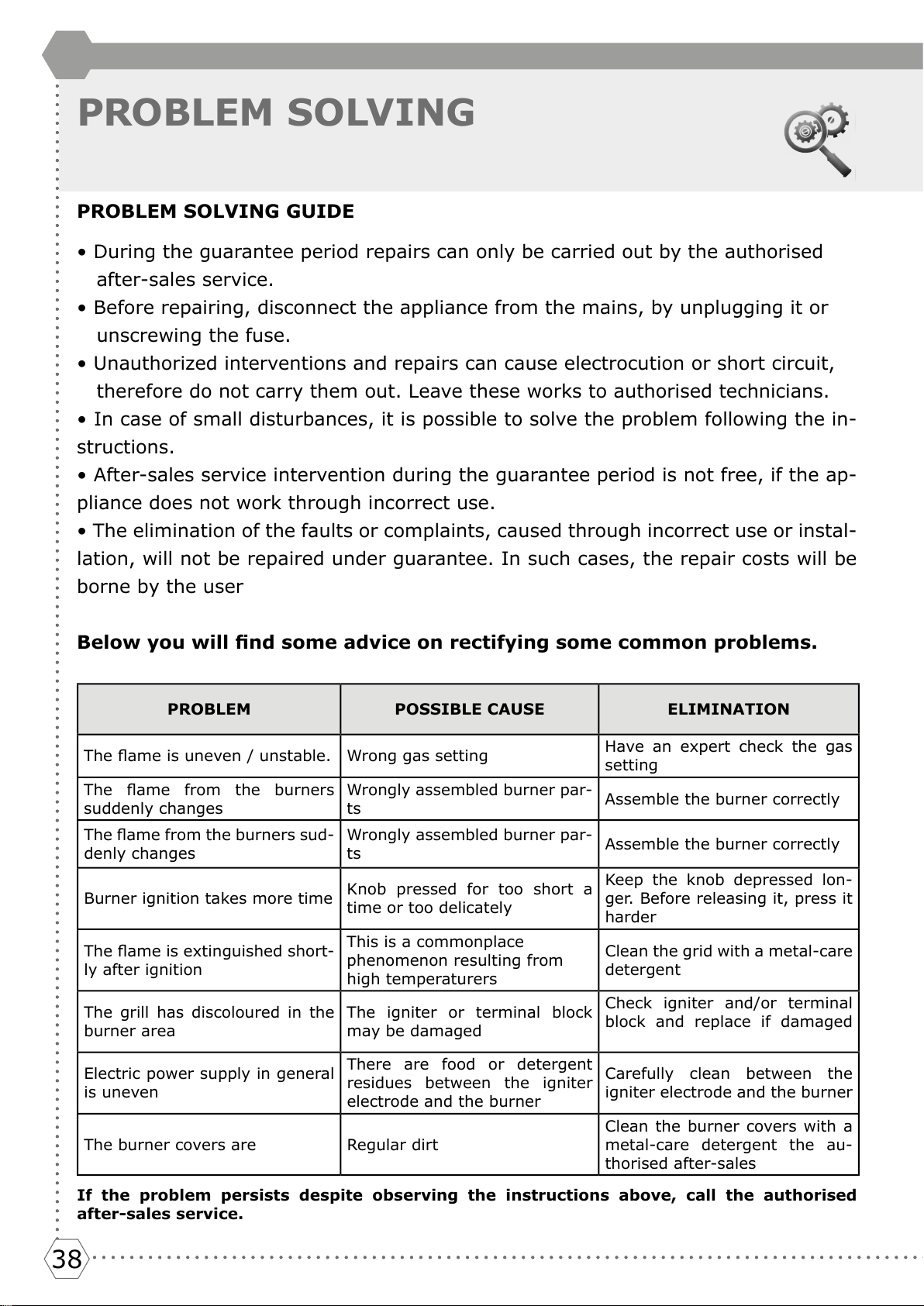
PROBLEM SOLVING GUIDE
• During the guarantee period repairs can only be carried out by the authorised
after-sales service.
• Before repairing, disconnect the appliance from the mains, by unplugging it or
unscrewing the fuse.
• Unauthorized interventions and repairs can cause electrocution or short circuit,
therefore do not carry them out. Leave these works to authorised technicians.
• In case of small disturbances, it is possible to solve the problem following the in-
structions.
• After-sales service intervention during the guarantee period is not free, if the ap-
pliance does not work through incorrect use.
• The elimination of the faults or complaints, caused through incorrect use or instal-
lation, will not be repaired under guarantee. In such cases, the repair costs will be
borne by the user
Below you will nd some advice on rectifying some common problems.
PROBLEM POSSIBLE CAUSE ELIMINATION
The ame is uneven / unstable. Wrong gas setting
Have an expert check the gas
setting
The ame from the burners
suddenly changes
Wrongly assembled burner par-
ts
Assemble the burner correctly
The ame from the burners sud-
denly changes
Wrongly assembled burner par-
ts
Assemble the burner correctly
Burner ignition takes more time
Knob pressed for too short a
time or too delicately
Keep the knob depressed lon-
ger. Before releasing it, press it
harder
The ame is extinguished short-
ly after ignition
This is a commonplace
phenomenon resulting from
high temperaturers
Clean the grid with a metal-care
detergent
The grill has discoloured in the
burner area
The igniter or terminal block
may be damaged
Check igniter and/or terminal
block and replace if damaged
Electric power supply in general
is uneven
There are food or detergent
residues between the igniter
electrode and the burner
Carefully clean between the
igniter electrode and the burner
The burner covers are Regular dirt
Clean the burner covers with a
metal-care detergent the au-
thorised after-sales
If the problem persists despite observing the instructions above, call the authorised
after-sales service.
3939
I
N
S
T
A
L
L
E
R
39
GB
NOTES
Del et e
36
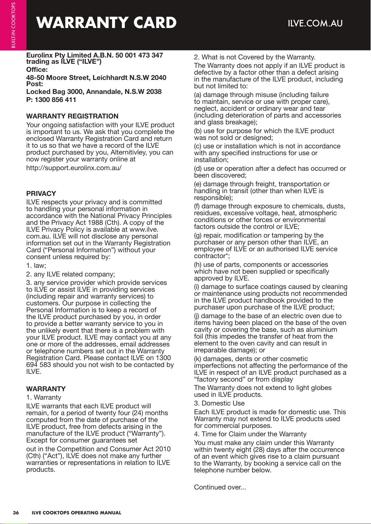
Eurolinx Pty Limited A.B.N. 50 001 473 347
trading as ILVE (“ILVE”)
Office:
48-50 Moore Street, Leichhardt N.S.W 2040
Post:
Locked Bag 3000, Annandale, N.S.W 2038
P: 1300 856 411
WARRANTY REGISTRATION
Your ongoing satisfaction with your ILVE product
is important to us. We ask that you complete the
enclosed Warranty Registration Card and return
it to us so that we have a record of the ILVE
product purchased by you, Alternitivley, you can
now register your warranty online at
http://support.eurolinx.com.au/
PRIVACY
ILVE respects your privacy and is committed
to handling your personal information in
accordance with the National Privacy Principles
and the Privacy Act 1988 (Cth). A copy of the
ILVE Privacy Policy is available at www.ilve.
com.au. ILVE will not disclose any personal
information set out in the Warranty Registration
Card (“Personal Information”) without your
consent unless required by:
1. law;
2. any ILVE related company;
3. any service provider which provide services
to ILVE or assist ILVE in providing services
(including repair and warranty services) to
customers. Our purpose in collecting the
Personal Information is to keep a record of
the ILVE product purchased by you, in order
to provide a better warranty service to you in
the unlikely event that there is a problem with
your ILVE product. ILVE may contact you at any
one or more of the addresses, email addresses
or telephone numbers set out in the Warranty
Registration Card. Please contact ILVE on 1300
694 583 should you not wish to be contacted by
ILVE.
WARRANTY
1. Warranty
ILVE warrants that each ILVE product will
remain, for a period of twenty four (24) months
computed from the date of purchase of the
ILVE product, free from defects arising in the
manufacture of the ILVE product (“Warranty”).
Except for consumer guarantees set
out in the Competition and Consumer Act 2010
(Cth) (“Act”), ILVE does not make any further
warranties or representations in relation to ILVE
products.
2. What is not Covered by the Warranty.
The Warranty does not apply if an ILVE product is
defective by a factor other than a defect arising
in the manufacture of the ILVE product, including
but not limited to:
(a) damage through misuse (including failure
to maintain, service or use with proper care),
neglect, accident or ordinary wear and tear
(including deterioration of parts and accessories
and glass breakage);
(b) use for purpose for which the ILVE product
was not sold or designed;
(c) use or installation which is not in accordance
with any specied instructions for use or
installation;
(d) use or operation after a defect has occurred or
been discovered;
(e) damage through freight, transportation or
handling in transit (other than when ILVE is
responsible);
(f) damage through exposure to chemicals, dusts,
residues, excessive voltage, heat, atmospheric
conditions or other forces or environmental
factors outside the control or ILVE;
(g) repair, modication or tampering by the
purchaser or any person other than ILVE, an
employee of ILVE or an authorised ILVE service
contractor*;
(h) use of parts, components or accessories
which have not been supplied or specically
approved by ILVE.
(i) damage to surface coatings caused by cleaning
or maintenance using products not recommended
in the ILVE product handbook provided to the
purchaser upon purchase of the ILVE product;
(j) damage to the base of an electric oven due to
items having been placed on the base of the oven
cavity or covering the base, such as aluminium
foil (this impedes the transfer of heat from the
element to the oven cavity and can result in
irreparable damage); or
(k) damages, dents or other cosmetic
imperfections not aecting the performance of the
ILVE in respect of an ILVE product purchased as a
“factory second” or from display
The Warranty does not extend to light globes
used in ILVE products.
3. Domestic Use
Each ILVE product is made for domestic use. This
Warranty may not extend to ILVE products used
for commercial purposes.
4. Time for Claim under the Warranty
You must make any claim under this Warranty
within twenty eight (28) days after the occurrence
of an event which gives rise to a claim pursuant
to the Warranty, by booking a service call on the
telephone number below.
Continued over...
WARRANTY CARD
ILVE.COM.AU
BUILT-IN COOKTOPS
ILVE COOKTOPS OPERATING MANUAL
37
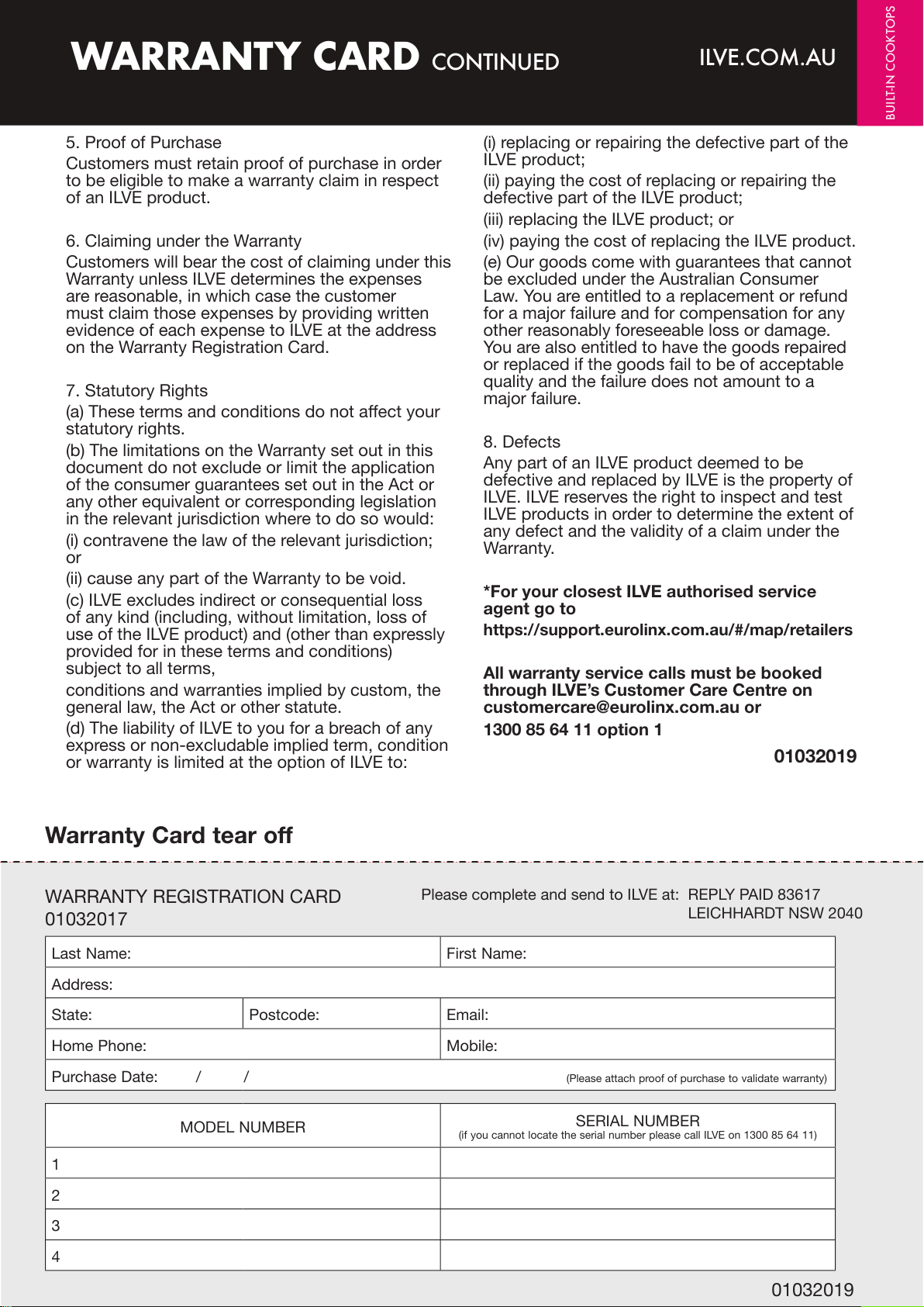
5. Proof of Purchase
Customers must retain proof of purchase in order
to be eligible to make a warranty claim in respect
of an ILVE product.
6. Claiming under the Warranty
Customers will bear the cost of claiming under this
Warranty unless ILVE determines the expenses
are reasonable, in which case the customer
must claim those expenses by providing written
evidence of each expense to ILVE at the address
on the Warranty Registration Card.
7. Statutory Rights
(a) These terms and conditions do not aect your
statutory rights.
(b) The limitations on the Warranty set out in this
document do not exclude or limit the application
of the consumer guarantees set out in the Act or
any other equivalent or corresponding legislation
in the relevant jurisdiction where to do so would:
(i) contravene the law of the relevant jurisdiction;
or
(ii) cause any part of the Warranty to be void.
(c) ILVE excludes indirect or consequential loss
of any kind (including, without limitation, loss of
use of the ILVE product) and (other than expressly
provided for in these terms and conditions)
subject to all terms,
conditions and warranties implied by custom, the
general law, the Act or other statute.
(d) The liability of ILVE to you for a breach of any
express or non-excludable implied term, condition
or warranty is limited at the option of ILVE to:
(i) replacing or repairing the defective part of the
ILVE product;
(ii) paying the cost of replacing or repairing the
defective part of the ILVE product;
(iii) replacing the ILVE product; or
(iv) paying the cost of replacing the ILVE product.
(e) Our goods come with guarantees that cannot
be excluded under the Australian Consumer
Law. You are entitled to a replacement or refund
for a major failure and for compensation for any
other reasonably foreseeable loss or damage.
You are also entitled to have the goods repaired
or replaced if the goods fail to be of acceptable
quality and the failure does not amount to a
major failure.
8. Defects
Any part of an ILVE product deemed to be
defective and replaced by ILVE is the property of
ILVE. ILVE reserves the right to inspect and test
ILVE products in order to determine the extent of
any defect and the validity of a claim under the
Warranty.
*For your closest ILVE authorised service
agent go to
https://support.eurolinx.com.au/#/map/retailers
All warranty service calls must be booked
through ILVE’s Customer Care Centre on
customercare@eurolinx.com.au or
1300 85 64 11 option 1
01032019
37ILVE Operating Manual
Please complete and send to ILVE at: REPLY PAID 83617
LEICHHARDT NSW 2040
Last Name: First Name:
Address:
State: Postcode: Email:
Home Phone: Mobile:
Purchase Date: / /
(Please attach proof of purchase to validate warranty)
MODEL NUMBER
SERIAL NUMBER
(if you cannot locate the serial number please call ILVE on 1300 85 64 11)
1
2
3
4
WARRANTY REGISTRATION CARD
01032017
01032019
Warranty Card tear off
WARRANTY CARD CONTINUED
ILVE.COM.AU
BUILT-IN COOKTOPS
38
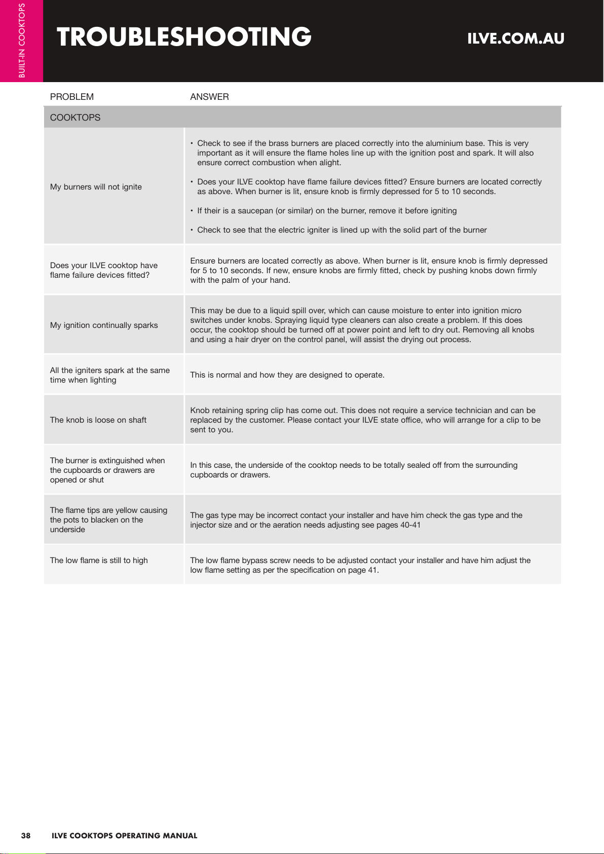
PROBLEM ANSWER
COOKTOPS
My burners will not ignite
• Check to see if the brass burners are placed correctly into the aluminium base. This is very
important as it will ensure the flame holes line up with the ignition post and spark. It will also
ensure correct combustion when alight.
• Does your ILVE cooktop have flame failure devices fitted? Ensure burners are located correctly
as above. When burner is lit, ensure knob is firmly depressed for 5 to 10 seconds.
• If their is a saucepan (or similar) on the burner, remove it before igniting
• Check to see that the electric igniter is lined up with the solid part of the burner
Does your ILVE cooktop have
flame failure devices fitted?
Ensure burners are located correctly as above. When burner is lit, ensure knob is firmly depressed
for 5 to 10 seconds. If new, ensure knobs are firmly fitted, check by pushing knobs down firmly
with the palm of your hand.
My ignition continually sparks
This may be due to a liquid spill over, which can cause moisture to enter into ignition micro
switches under knobs. Spraying liquid type cleaners can also create a problem. If this does
occur, the cooktop should be turned off at power point and left to dry out. Removing all knobs
and using a hair dryer on the control panel, will assist the drying out process.
All the igniters spark at the same
time when lighting
This is normal and how they are designed to operate.
The knob is loose on shaft
Knob retaining spring clip has come out. This does not require a service technician and can be
replaced by the customer. Please contact your ILVE state office, who will arrange for a clip to be
sent to you.
The burner is extinguished when
the cupboards or drawers are
opened or shut
In this case, the underside of the cooktop needs to be totally sealed off from the surrounding
cupboards or drawers.
The flame tips are yellow causing
the pots to blacken on the
underside
The gas type may be incorrect contact your installer and have him check the gas type and the
injector size and or the aeration needs adjusting see pages 40-41
The low flame is still to high The low flame bypass screw needs to be adjusted contact your installer and have him adjust the
low flame setting as per the specification on page 41.
TROUBLESHOOTING
ILVE.COM.AU
BUILT-IN COOKTOPS
ILVE COOKTOPS OPERATING MANUAL
39
01012018
facebook.com/ILVEappliances
twitter.com/ILVE_appliances
youtube.com/ILVEappliances
livewithilve.com
You can now find us on:
iWarranty
REGISTER YOUR WARRANTY ONLINE NOW
GO TO: https://support.eurolinx.com.au/#/form/warrantyregistration
NOTES
ILVE.COM.AU
BUILT-IN COOKTOPS
ILVE COOKTOPS OPERATING MANUAL

40
