Loading ...
Loading ...
Loading ...
43
W415-0748 / 12.12.08
A
B
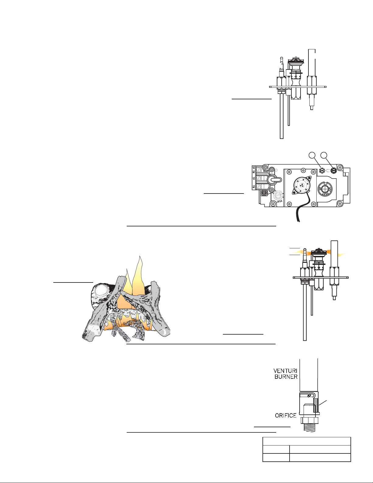
Adjust the pilot screw to provide properly sized flame. Turn in a clockwise
direction to reduce the gas flow.
Inlet pressure can be checked by turning screw (A)
counter-clockwise until loosened and then placing pressure gauge
tubing over the test point. Gauge should read 7” (minimum 4.5”)
water column for natural gas or 13” (11” minimum) water column
for propane. Check that main burner is operating on “HI”.
Outlet pressure can be checked the same as above using screw (B).
Gauge should read 3.5” water column for natural gas or 10” water column
for propane. Check that main burner is operating on “HI”.
AFTER TAKING PRESSURE READINGS, TIGHTEN SCREWS FIRMLY
TO SEAL. DO NOT OVER TORQUE. LEAK TEST.
FLAME MUST
ENVELOPE UPPER
3/8" TO 1/2" OF
THERMOCOUPLE &
THERMOPILE
PILOT
BURNER
39.2
THERMOCOUPLE
THERMOPILE
AIR SHUTTER OPENINGS
LP 1/2”
NG 1/16”
10.0 ADJUSTMENTS
10.1 PILOT BURNER ADJUSTMENT
10.2 FLAME CHARACTERISTICS
10.3 VENTURI ADJUSTMENT
FIGURE 10.1b
FIGURE 10.1a
FIGURE 10.2b
FIGURE 10.2a
FIGURE 10.3
It is important to periodically perform a visual check of the pilot and burner
flames. Compare them to the illustration below.
54.2
3/8” - 1/2”
This
f
ireplace model has an air shutter that has been
f
actory set open according to the
chart below:
Closing the air shutter will cause a more yellow flame, but can lead to carboning.
Opening the air shutter will cause a more blue flame, but can cause flame lifting
from the burner ports. The flame may not appear yellow immediately; allow 15
to 30 minutes for the final flame color to be established.
AIR SHUTTER ADJUSTMENT MUST ONLY BE DONE BY A QUALIFIED
INSTALLER!
AIR
SHUTTER
OPENING
49.1
Loading ...
Loading ...
Loading ...