Loading ...
Loading ...
Loading ...
22
W415-0748 / 12.12.08
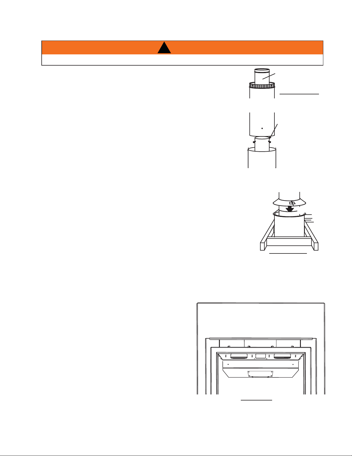
3.3.3 VERTICAL AIR TERMINAL INSTALLATION
A. Move the fireplace into position.
B. Fasten the roof support to the roof using the screws provided. The roof support is optional.
In this case the venting is to be adequately supported using either an alternate method
suitable to the authority having jurisdiction or the optional roof support.
C. Apply high temperature sealant W573-0007 (not supplied) to the outer edge of the
inner sleeve of the air terminal. Slip the inner coupler a minimum of 2" over the sleeve
and secure using 3 screws.
D. Apply high temperature sealant W573-0002 (not supplied) to the outer edge of the of
the outside sleeve of the air terminal connector. Slip the outer coupler over the sleeve
and secure as before. Trim the outer coupler even with the inner coupler end.
E. Thread the air terminal connector / vent pipe assembly down through the roof support
and attach, ensuring that a minimum 16" of air terminal connector will penetrate the
roof when fastened. If the attic space is tight, we recommend threading the Wolf Steel
vent pipe collar or equivalent loosely onto the air terminal connector / vent pipe
assembly as it is passed through the attic. The air terminal connector must be located
vertically and plumb.
F. Remove nails from the shingles, above and to the sides of the chimney. Place the flashing over the air terminal
connector and slide it underneath the sides and upper edge of the shingles. Ensure that the air terminal connector is
properly centered within the flashing, giving a 3/4" margin all around. Fasten to the roof. Do NOT
nail through the lower portion of the flashing. Make weather-tight by sealing with caulking.
Where possible, cover the sides and top edges of the flashing with roofing material.
G. Apply a heavy bead of waterproof caulking 2" above the flashing. Install the storm collar around
the air terminal and slide down to the caulking. Tighten to ensure that a weather-tight seal
between the air terminal connector and the collar is achieved.
H. Continue adding rigid venting sections, sealing and securing as above. Attach the inner
collapsed telescopic sleeve to the last section of rigid piping. Secure with screws and seal.
Repeat using the outer telescopic sleeve.
I. Run a bead of high temperature sealant W573-0007 (not supplied) around the outside of the inner collar on the fireplace.
Pull the telescopic sleeve a minimum of 2" onto the collar. Secure with 3 screws. Repeat with the outer telescopic sleeve.
J. In the attic, slide the vent pipe collar down to cover up the open end of the shield and tighten. This will prevent any
materials, such as insulation, from filling up the 1" air space around the pipe.
INNER RIGID
PIPE
OUTER
RIGID PIPE
INNER PIPE
HIGH
TEMPERATURE
SEALANT
AIR
TERMINAL
CONNECTOR
VENT
PIPE
SHIELD
VENT
PIPE
COLLAR
3.4 RESTRICTING VERTICAL VENTS
FLUE COLLAR
RESTRICTOR PLATE
TOP OF FIREBOX
Vertical terminations may display a very active fl ame. If this
appearance is not desirable, the vent exit must be restricted
using restrictor plate W500-0205. This reduces the velocity
of the exhaust gases, slowing down the fl ame pattern and
creating a more traditional appearance.
The plate has a series of holes to allow for adjustment.
Remove the two screws on either side of the exhaust col-
lar inside the fi rebox. Install the plate in the desired set of
holes, then replace the screws.
It is recommended to secure in the third set of holes which
causes the greatest amount of restriction for vent lengths
between 15 and 30 feet.
FIGURE 3.3.3j
FIGURE 3.3.3a
FIGURE 3.4
!
WARNING
Maintain a minimum 2” space between the air inlet base and the storm collar.
Loading ...
Loading ...
Loading ...