Loading ...
Loading ...
Loading ...
30
Part No. 80106286
Revision C
OperationControls
OPERATION
Controls
WARNING
Failure to read and obey the
operator’s manual, all warnings, and operating
instructions could result in death or serious injury.
Front View
C
D
F
G
H
K
A
J
B
E
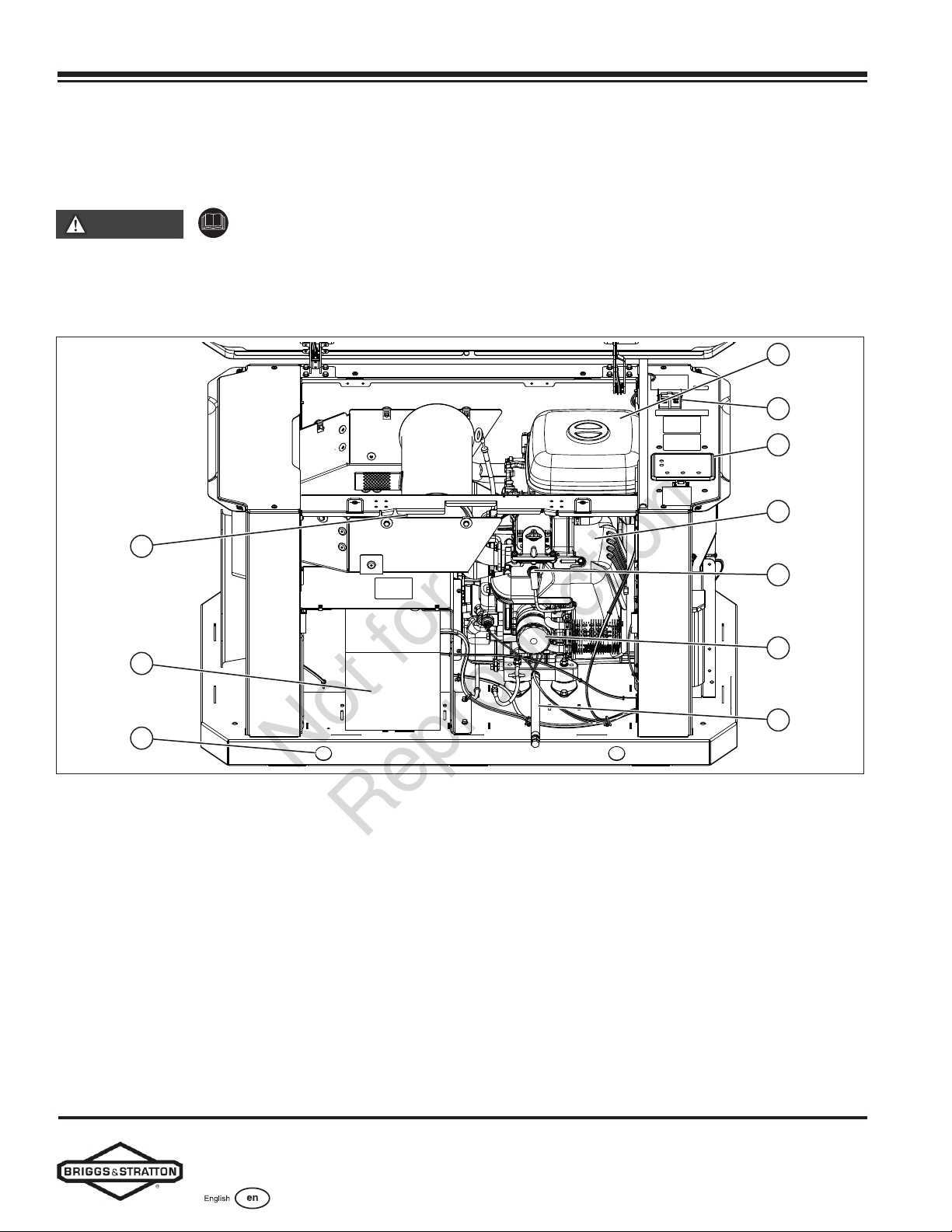
Figure 18
Generator is shown with roof and access covers removed
for clarity. Legend for System Connector Locations:
(A) Lifting Holes — Provided at each corner for lifting generator
(B) Muler — High-performance muler lowers engine noise to
comply with most residential codes
(C) Circuit Breaker — Protects the system from shorts and other
over-current conditions
(D) Controller — Facilitates for generator operation control, menu
start-up, and informational display functions
(E) Air Cleaner — Uses a dry-type filter element to protect
engine by filtering dust and debris out of intake air
(F) Engine Label — Identifies engine model and type (located on
the valve cover)
(G) Spark Plug — A device in the cylinder head of the engine
that ignites the fuel mixture by means of an electric
spark
(H) Oil Filter — Filters engine oil to prolong generator life
(J) Battery (installer supplied) — 12VDC, lead acid,
automotive-style battery provides power to start the
engine
(K) Oil Drain Hose — Facilitates oil changing
Not for
Reproduction
Loading ...
Loading ...
Loading ...