Loading ...
Loading ...
Loading ...
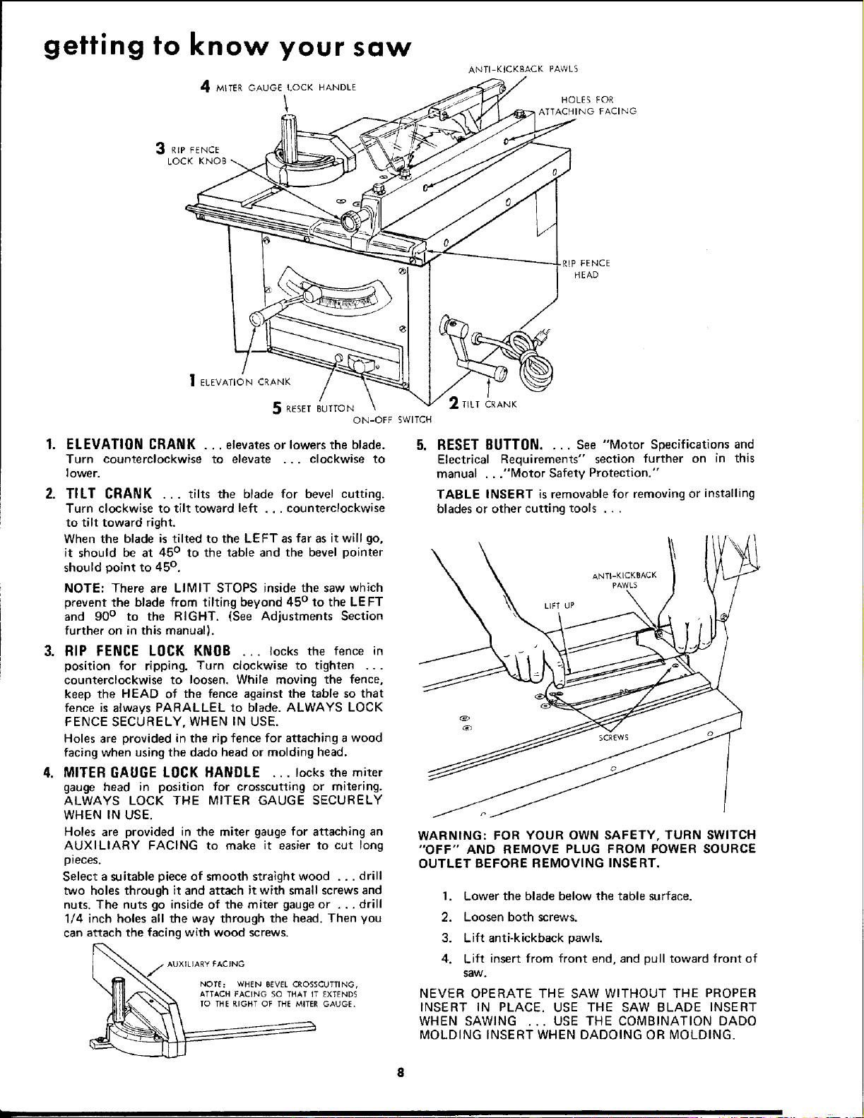
getting to know your saw
4 MITER GAUGE LOCK HANDLE
ANTI-KICKBACK PAWLS
HOLES FOR
ATTACHING FACING
3 RIP FENCE
LOCK
I ELEVATION CRANK
5 RESET BUTTON
ON-OFF SWITCH
TILT CRANK
ELEVATION CRANK ... elevatesor lowersthe blade.
Turn counterclockwise to elevate ... clockwise to
Iower.
2. TILT CRANK ... tilts the blade for bevel cutting.
Turn clockwise to tilt toward left ... counterclockwise
to tilt toward right.
When the blade is tilted to the LEFT asfar as it will go,
it should be at 45° to the table and the bevel pointer
should point to 45°.
NOTE: There are LIMIT STOPS inside the saw which
prevent the blade from tilting beyond 45 ° to the LEFT
and 90° to the RIGHT. (See Adjustments Section
further on in this manual).
3. RIP FENCE LOCK KNOB ... locks the fence in
position for ripping. Turn clockwise to tighten ...
counterclockwise to loosen, While moving the fence,
keep the HEAD of the fence against the table so that
fence is always PARALLEL to blade. ALWAYS LOCK
FENCE SECURELY, WHEN IN USE.
Holes are provided in the rip fence for attaching a wood
facing when usingthe dado head or molding head.
4. MITER fiAIJGE LOCK HANDLE ... locks the miter
gauge head in position for crosscutting or mitering.
ALWAYS LOCK THE MITER GAUGE SECURELY
WHEN IN USE.
Holes are provided in the miter gaugefor attaching an
AUXILIARY FACING to make it easier to cut long
pieces.
Select a suitable piece of smooth straight wood ... drill
two holes through it and attach it with small screws and
nuts. The nuts go inside of the miter gaugeor ... drill
1/4 inch holes all the way through the head. Then you
can attach the facing with wood screws.
AUXILIARY PACING
NOTE: WHEN BEVEL CROSSCUTTING,
ATTACH FACING SO THAT IT EXTENDS
TO THE RIGHT OF THE MITER GAUGE,
RESET BUTTON.... See "Motor Specifications and
Electrical Requirements" section further on in this
manual ..."Motor Safety Protection."
TABLE INSERT isremovable for removing or installing
blades or other cutting tools ...
LIFT LIP
WARNING: FOR YOUR OWN SAFETY, TURN SWITCH
"OFF" AND REMOVE PLUG FROM POWER SOURCE
OUTLET BEFORE REMOVING INSERT.
1. Lower the blade below the table surface.
2. Loosen both screws.
3. Lift anti-kickback pawls,
4, Lift insert from front end, and pull toward front of
SaW.
NEVER OPERATE THE SAW WITHOUT THE PROPER
INSERT IN PLACE. USE THE SAW BLADE INSERT
WHEN SAWING ... USE THE COMBINATION DADO
MOLDING INSERT WHEN DADOING OR MOLDING.
Loading ...
Loading ...
Loading ...