Loading ...
Loading ...
Loading ...
RABBETING
Rabbeting is known as cutting out a section of the corner
of a piece of material.
To make a RABBET requires two cuts which do not go all
the way through the material. Therefore the blade guard
must be removed.
1. Remove blade guard.
2. Adjust rip fence and blade to required dimensions.
3. Make first cut through edge. Follow resawing
procedure.
4. Remove auxiliary fence and make second cut.
RABBET
5. INSTALL BLADE GUARD IMMEDIATELY UPON
COMPLETION OF RABBETING OPERATION.
Rabbet cuts can also be made using the dado head or
molding head.
adjustments
WARNING: FOR YOUR OWN SAFETY, TURN
SWITCH "OFF" AND REMOVE PLUG FROM POWER
SOURCE OUTLET BEFORE MAKING ANY
ADJUSTMENTS.
MITER GAUGE
NOTE: The graduations are manufactured to very close
tolerances which provide suitable accuracy for average
woodworking. In some cases where extreme accuracy is
required, when making angle cuts, for example, make a trial
cut and then recheck it.
If necessary, the miter gauge head can then be swiveled
slightly to compensate and then locked.
The HEAD should be SQUARE (900 ) with the bar when
the pointer points to "0".
To check for squareness, place an accurate square on the
miter gauge. If the head is NOT SQUARE with the bar:
1. Loosen the lock handle.
2. Position the head square with the bar ... tighten the
handle.
HEELING ADJUSTMENT or PARALLELISM OF
SAWBLADE TO MITER GAUGE GROOVE.
While cutting, the material must move in a straight line
PARALLEL to the SAWBLADE . . . therefore both the
miter gauge GROOVE and the RIP FENCE must be
PARALLEL to the SAWBLADE.
If the sawblade IS NOT parallel to the miter gauge groove,
the blade will bind at one end of the cut.
To check for parallelism:
WARNING - FOR YOUR OWN SAFETY, TURN SWITCH
"OFF AND REMOVE PLUG FROM POWER SOURCE
OUTLET.
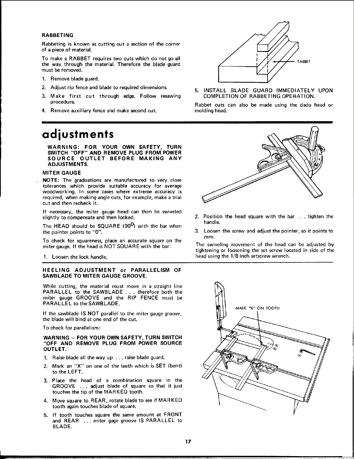
1. Raise blade all the way up . ., raise blade guard.
2. Mark an "X" on one of the teeth which is SET (bent)
to the LEFT.
3. Place the head of a combination square in the
GROOVE ... adjust blade of square so that it just
touches the tip of the MARKED tooth.
4. Move square to REAR, rotate blade to see if MARKED
tooth again touches blade of square.
5. If tooth touches square the same amount at FRONT
and REAR ... miter gage groove IS PARALLEL to
BLADE.
3. Loosen the screw and adjust the pointer, so it points to
zero.
The swiveling movement of the bead can be adjusted by
tightening or loosening the set screw located in side of the
head using the 1/8 inch setscrew wrench.
MARK "X" ON TOOTH
17
m.
Loading ...
Loading ...
Loading ...