Loading ...
Loading ...
Loading ...
Recheck all locking handles. They must be tightened securely.
• Make sure all moving parts are free and clear of any
interference.
• Make sure all fasteners are tight and have not vibrated loose.
• With power disconnected, test operation by hand for clear-
ance and adjust if necessary.
• Always wear eye protection or face shield.
• After turning switch on, always allow the spindle to come
up to full speed before turning.
• Be sure motor runs counterclockwise when viewing spindle
from the right end (inboard side of headstock).
• Keep hands clear of spindle, centers, faceplates and other
moving parts of machine.
For optimum performance, do not stall motor or reduce
speed. Do not force the tool into the work.
ON-OFF SWITCH
Refer to Figure 13.
Power supply to the lathe is controlled by the locking rocker
switch. To turn lathe on:
• Switch on the rocker switch.
To turn lathe off:
• Switch off the rocker switch.
The rocker switch has a removable key to prevent unautho-
rized use or accidental start-up of the lathe. Removing the key
will lock the lathe from use.
To lock the lathe:
• Switch off the rocker switch.
• Disconnect the line cord from power source.
• Pull out the removable key. The key has the words,
"Remove to Lock".
• Store key in a safe place
NOTE: With the key removed, the rocker can be "ROCKED",
but the switch cannot be actuated.
To unlock the lathe:
• Position the rocker in the OFF position.
Insert the key into the rocker.
• Connect line cord to power source.
• The switch can now be actuated.
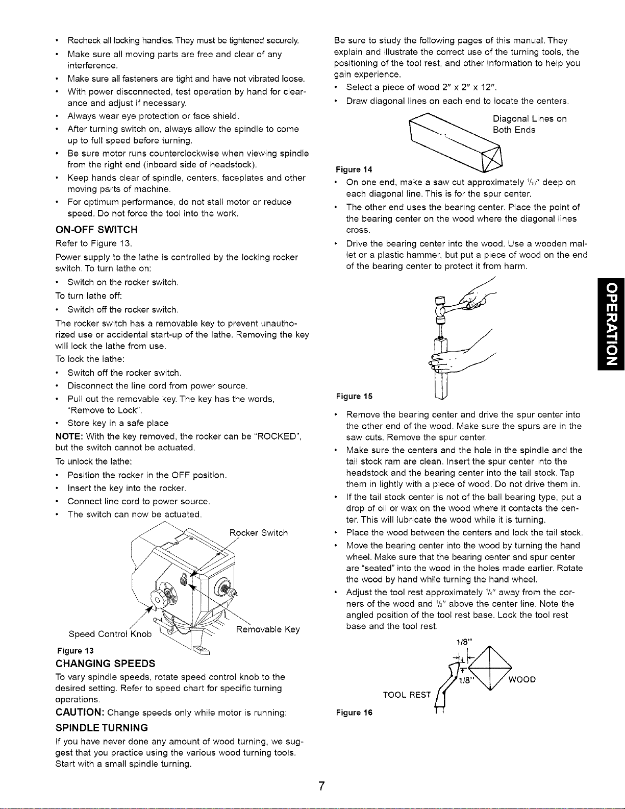
Rocker Switch
/,
Removable Key
Speed Control Knob
Figure 13
CHANGING SPEEDS
To vary spindle speeds, rotate speed control knob to the
desired setting. Refer to speed chart for specific turning
operations.
CAUTION: Change speeds only while motor is running:
SPINDLE TURNING
If you have never done any amount of wood turning, we sug-
gest that you practice using the various wood turning tools.
Start with a small spindle turning.
Be sure to study the following pages of this manual. They
explain and illustrate the correct use of the turning tools, the
positioning of the tool rest, and other information to help you
gain experience.
Select a piece of wood 2" x 2" x 12".
Draw diagonal lines on each end to locate the centers.
Diagonal Lines on
Both Ends
Figure 14
On one end, make a saw cut approximately _/,6"deep on
each diagonal line. This is for the spur center.
The other end uses the bearing center. Place the point of
the bearing center on the wood where the diagonal lines
cross.
Drive the bearing center into the wood. Use a wooden mal-
let or a plastic hammer, but put a piece of wood on the end
of the bearing center to protect it from harm.
Figure 15
Remove the bearing center and drive the spur center into
the other end of the wood. Make sure the spurs are in the
saw cuts. Remove the spur center.
Make sure the centers and the hole in the spindle and the
tail stock ram are clean. Insert the spur center into the
headstock and the bearing center into the tail stock. Tap
them in lightly with a piece of wood. Do not drive them in.
If the tail stock center is not of the ball bearing type, put a
drop of oil or wax on the wood where it contacts the cen-
ter. This will lubricate the wood while it is turning.
Place the wood between the centers and lock the tail stock.
Move the bearing center into the wood by turning the hand
wheel. Make sure that the bearing center and spur center
are "seated" into the wood in the holes made earlier. Rotate
the wood by hand while turning the hand wheel.
Adjust the tool rest approximately %" away from the cor-
ners of the wood and %" above the center line. Note the
angled position of the tool rest base. Lock the tool rest
base and the tool rest.
Figure 16
1/8"
4 wooo
TOOL REST
Loading ...
Loading ...
Loading ...