Loading ...
Loading ...
Loading ...
RefertoFigures2-6.
CAUTION:Donotattemptassemblyifpartsaremissing.
Usethismanualtoorderreplacementparts.
Removeallcomponentsfromtheshippingcartonandverify
againstthepartslistonpage3.Cleaneachcomponentand
removeshippingpreservatives(coatings)asrequired.
• Afterselectinganappropriatebench,table,orlathestand,set
thebedtowardsthefrontandtheleftside.
• Turnbedonitssidewiththebottomofthebedfacing
towardsyouandwiththeheadstockendofthebedonthe
leftside.
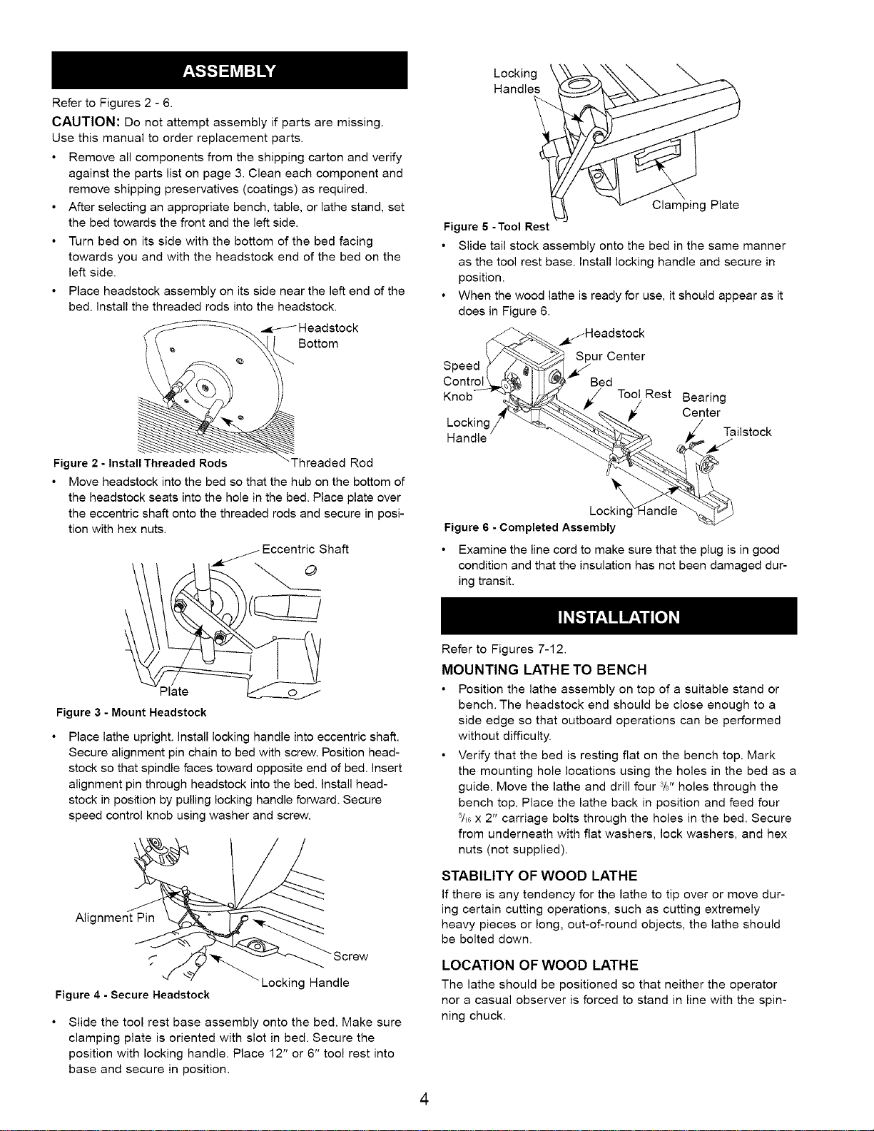
Placeheadstockassemblyonitssideneartheleftendofthe
bed.installthethreadedrodsintotheheadstock.
Headstock
Bottom
Locking
Handles
ClampingPlate
Figure 6 -Tool Rest
• Slide tail stock assembly onto the bed in the same manner
as the tool rest base. Install locking handle and secure in
position.
• When the wood lathe is ready for use, it should appear as it
does in Figure 6.
_Headstock
Spur Center
Speed
Control Bed
Knob Tool Rest Bearing
Center
Tailstock
Handle
Figure 2 - Install Threaded Rods "Threaded Rod
Move headstock into the bed so that the hub on the bottom of
the headstock seats into the hole in the bed. Place plate over
the eccentric shaft onto the threaded rods and secure in posi-
tion with hex nuts.
//- Eccentric Shaft
Plate ______
Figure 3 - Mount Headstock
Place lathe upright, install locking handle into eccentric shaft.
Secure alignment pin chain to bed with screw. Position head-
stock so that spindle faces toward opposite end of bed. Insert
alignment pin through headstock into the bed. Install head-
stock in position by pulling locking handle forward. Secure
speed control knob using washer and screw.
\
Locking
Figure 6 - Completed Assembly
• Examine the line cord to make sure that the plug is in good
condition and that the insulation has not been damaged dur-
ing transit.
Refer to Figures 7-12.
MOUNTING LATHE TO BENCH
• Position the lathe assembly on top of a suitable stand or
bench. The headstock end should be close enough to a
side edge so that outboard operations can be performed
without difficulty.
• Verify that the bed is resting flat on the bench top. Mark
the mounting hole locations using the holes in the bed as a
guide. Move the lathe and drill four 3/8"holes through the
bench top. Place the lathe back in position and feed four
5/_Gx 2" carriage bolts through the holes in the bed. Secure
from underneath with flat washers, lock washers, and hex
nuts (not supplied).
Alignment Pin
Figure 4 - Secure Headstock
Locking Handle
Slide the tool rest base assembly onto the bed. Make sure
clamping plate is oriented with slot in bed. Secure the
position with locking handle. Place 12" or 6" tool rest into
base and secure in position.
STABILITY OF WOOD LATHE
If there is any tendency for the lathe to tip over or move dur-
ing certain cutting operations, such as cutting extremely
heavy pieces or long, out-of-round objects, the lathe should
be bolted down.
LOCATION OF WOOD LATHE
The lathe should be positioned so that neither the operator
nor a casual observer is forced to stand in line with the spin-
ning chuck.
4
Loading ...
Loading ...
Loading ...