Loading ...
Loading ...
Loading ...
Wiring
Control Logic
LED DISPLAY
The control displays acve faults switchs on the
LED display. When the control displays the fault
switch and the LED flashes quickly, there is
something wrong with the system. Refer to the
detailed fault switchs.
When the paron control, DH is connected to
the DH port of the paron controller. When the
24V signal of DH changes to 0V, the air volume
drops to 80% of the nominal refrigeraon air
volume.
The WORK port is linked with the fan. When the
fan is running, the relay is closed; if an acve 24V
signal is required, it can be directly connected to
the G and C ports.
Indoor unit Connector
R 24V
C COM
G Fan
Y
Connector Purpose
Y/Y2
B
W
W1
W2
E/AUX
DH/DS/BK
L
First period cooling
Second period cooling
Heang(Four-way valve)
Heang operaon
Electric heang operaon 1
Electric heang operaon 2
Emergency heang
Drying regionally
Error signal
•
UV, fresh air or negave ion wiring
work
24V control signal or 208/230V power supply
UV, fresh wind or
negave ions, etc
CN23
Page 42
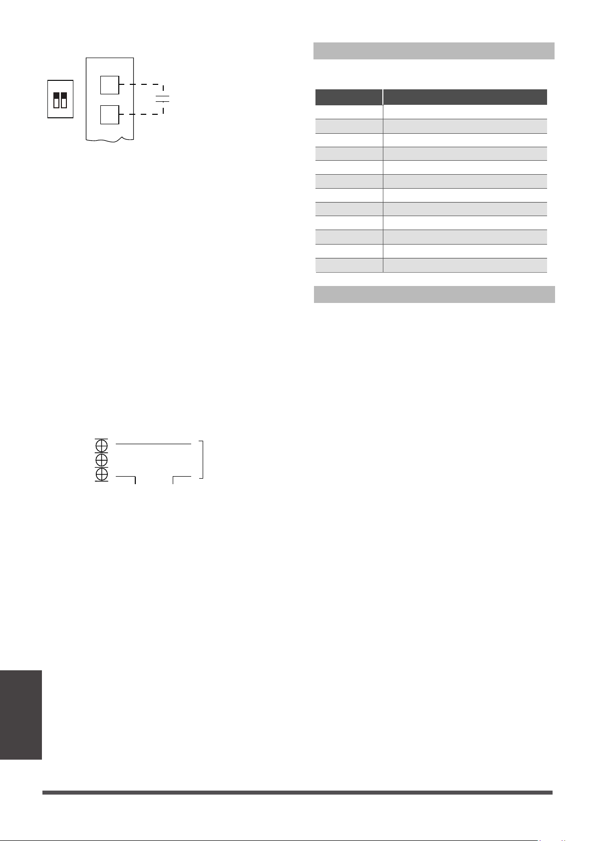
S4-1 DIP switch of
Perform disconnecon and short-circuit to
achieve paron, control or dehumidifcaon
Dehumidificaon control requires indirect
humidifier at DH and R. Set S4-1 as OFF.
When the humidity rises and exceeds the set
value of the humidifier, the 24V signal of DH
changes to 0V, the refrigeraon system starts the
dehumidificaon operaon, and the air volume
drops to 80% of the nominal refrigeraon air
volume.
•
Dehumidificaon control wiring
1 2
ON
S4
DH
R
HUMIDISTAT
Loading ...
Loading ...
Loading ...