Loading ...
Loading ...
Loading ...
3. Connect the u-lugs to the terminals
Match the wire colors/labels with the labels
on the terminal block. Firmly screw the u-lug
of each wire to its corresponding terminal.
Using a wire crimper, crimp u-lugs on the
ends.
b. Using wire strippers, strip the rubber
jackerom both ends of the signal cable
to reveal approximately 5.9” (15cm) of
wire.
c.
Strip the insulaon from the ends.
d.
NOTE: When connecng the wires, strictly
follow the wiring diagram found inside the
electrical box cover.
NOTE:
In North America, choose the cable
type according to the local electrical switchs
and regulaons.
In North America, please choose the
right cable size according to the Minimum
Circuit Ampacity indicated on the
nameplateof the unit.
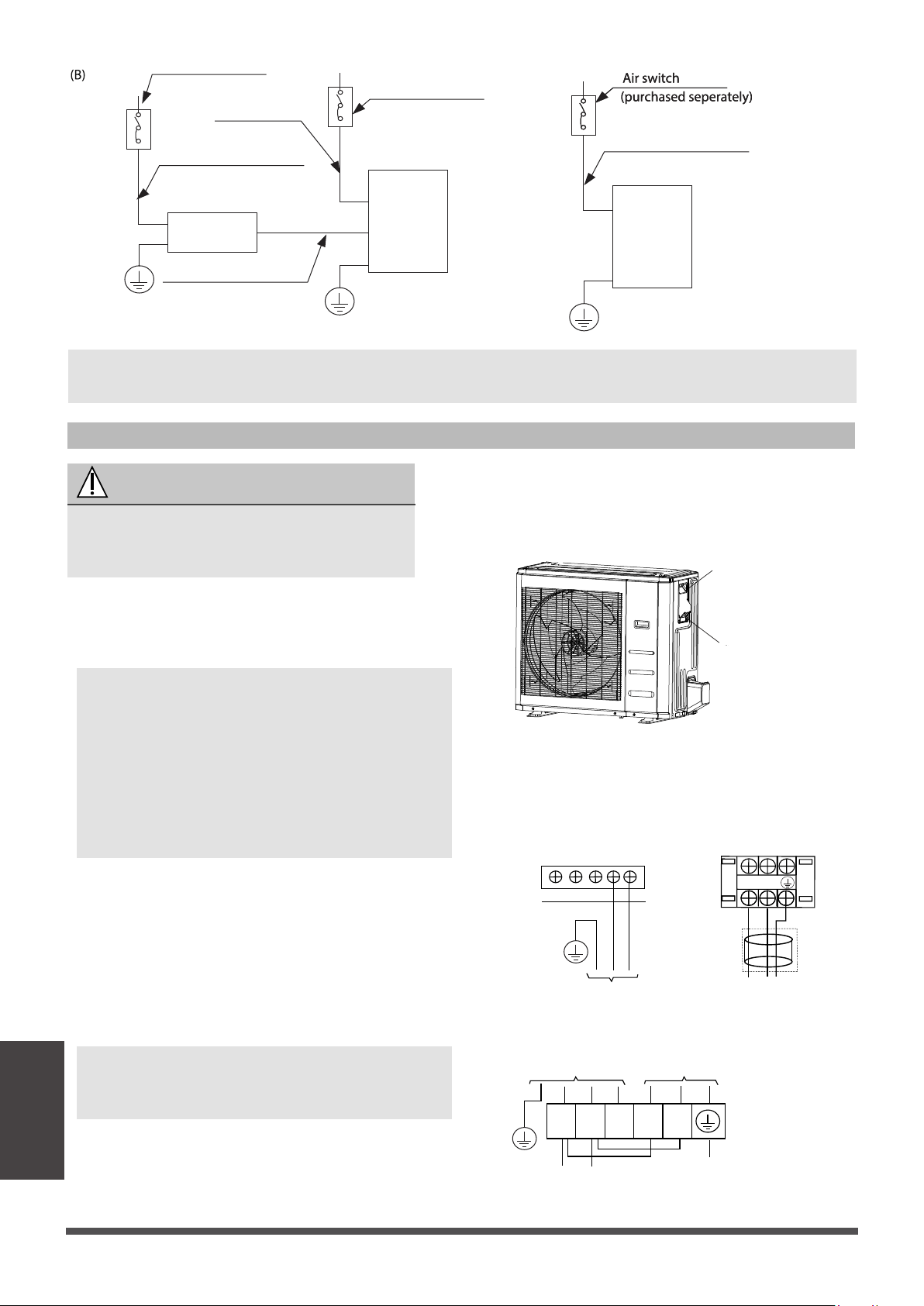
Outdoor Unit Wiring
WARNING
Before performing any electrical or wiring
work, turn off the main power to the
system.
1.
Prepare the cable for connecon
a. You must first choose the right cable
size.
NOTE: The cographs are for explanaon purpose only. Your machine may be slightly
different. The actual shape shall prevail.
2.
Remove the electric cover of the outdoor unit.
If there is no cover on the outdoor unit, take
off the bolts from the maintenance board
and remove the protecon board.
Cover
Screw
Electrical
heater
unit
Electrical heater unit power wires
Indoor unit
Outdoor unit
Air switch
(purchased seperately)
Air switch
(purchased seperately)
(purchased seperately)
Indoor unit power wires
Indoor & Outdoor
connecve wires
Outdoor unit power wires
Outdoor Unit A Outdoor Unit B
L2
L1
OPTIONAL
L1
TO POWER SOURCE
INDOOR UNIT POWER SUPPLY
TO POWER SOURCE
L2
Outdoor Unit C
1 2 3 L1 L2
Page 38
Wiring
Loading ...
Loading ...
Loading ...