Loading ...
Loading ...
Loading ...
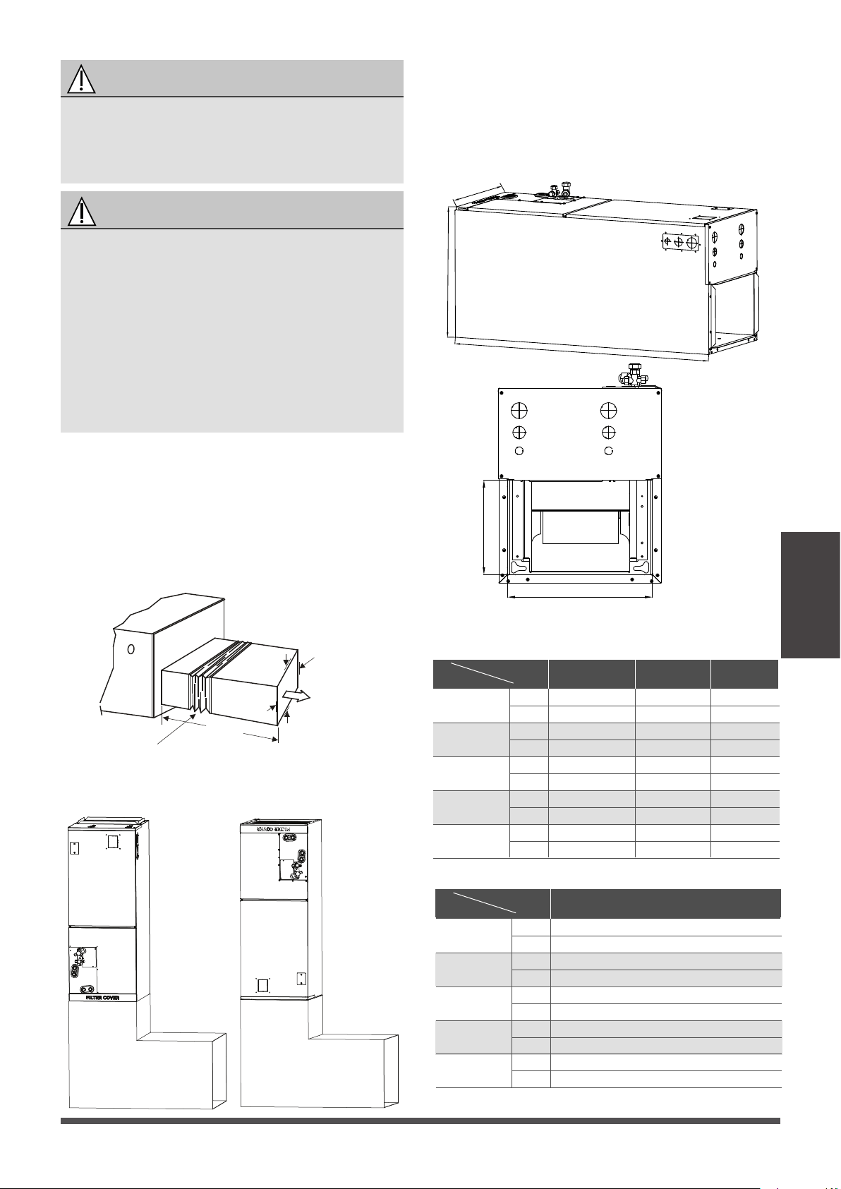
RECOMMENDED DISTANCES BETWEEN THE
INDOOR UNIT
The distance between the mounted indoor unit
should meet the specificaons illlustrated in the
following diagram.
Plenum Clearances
MINIMUM CLEARANCE
OF 1″/25.4mmALL SIDES
FLEXIBLE
DUCT COLLAR
The outlet side pipe length is 59’’/1.5m.
59’’/1.5m
Indoor parts installation size
MODEL(Btu/h)
Dimensions
Length of A
Length of B
12K~24K
1143
533
Length of C
Length of D
Length of E
445
400
260
30K~48K
1245
533
534
490
260
60K
1346
45
49 53
533
21
21 21
622
17-1/2
21-1/50 24-1/2
580
15-3/4
19-5/16 22-27/32
260
10-1/4 10-1/4 10-1/4
Vertical installations
Horizontal installations
A
B
C
E
D
mm
inch
mm
inch
mm
inch
mm
inch
mm
inch
MODEL(Btu/h)
Dimensions
Length of A
Length of B
60K
Length of C
Length of D
Length of E
1245
533
534
490
260
49
21
21-1/50
19-5/16
10-1/4
mm
inch
mm
inch
mm
inch
mm
inch
mm
inch
Page 17
Indoor Unit
Installation
(unit: inch/mm)
Model A(for North America models)
Model B
Fixing instructions: When installed vercally
(upward or downward), the lower end of the air
outlet needs to be connected to the L-shaped
metal air duct and fastened by screws.
WARNING
IMPORTANT
Use duct tape and/or Permagum to seal closed
any space around the holes where the drain lines
exit the cabinet. Warm air must not be allowed
to enter throughany gaps or holes in the cabinet.
There must be an airght seal between the
boom of the air handler and the return air
plenum. Use fiberglass sealing strips, caulking,
or equivalent sealing method between the
plenum and the air handler cabinet to ensure a
ght seal. Return air must not be drawn from a
room where this air handler or any gas-fueled
appliance (i.e., water heater), or carbon
monoxide-producingdevice (i.e., wood fireplace)
is installed.
Loading ...
Loading ...
Loading ...