Loading ...
Loading ...
Loading ...
Valve Guide Replacement
Mark new valve guides at the proper depth (see
specification; page 2-3) using a marker.
Chill the new valve guides in a freezer for about 1 hour.
Heat the cylinder head to 100 – 150 ˚C (212 – 300 ˚F)
with a hot plate or oven.
Do not heat the cylinder head beyond 180 ˚C (320 ˚F).
Use temperature indicator sticks, available from welding
supply stores, to be sure the cylinder head is heated to
the proper temperature.
Using a torch to heat the cylinder head may cause
warpage.
Support the cylinder head and drive the valve guides out
of the cylinder head from the combustion chamber side.
Tool:
Valve guide driver 07HMD–ML00101
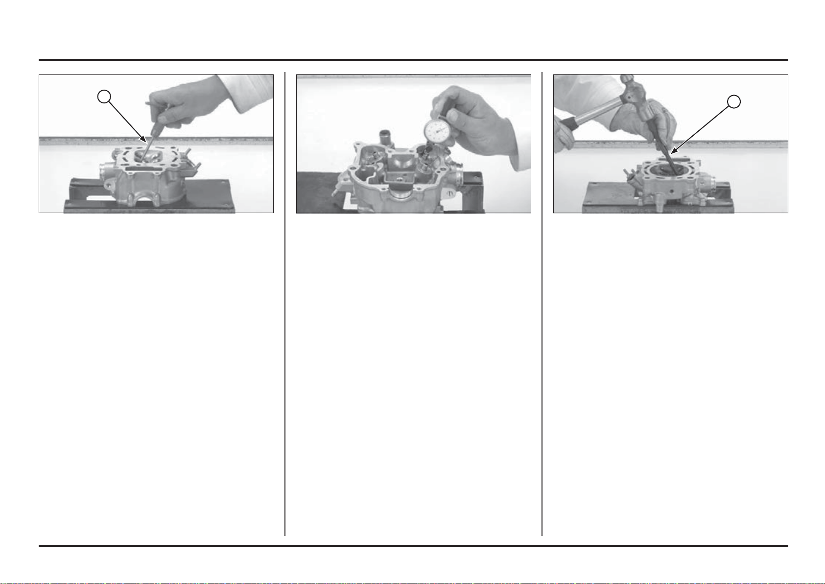
(1) VALVE GUIDE DRIVER
Measure and record the valve guide I.D. using a ball gauge
or inside micrometer.
Service limit:
IN/EX: 4.552 mm (0.1792 in)
Subtract each valve stem O.D. from the corresponding
guide I.D. to obtain the stem-to-guide clearance.
Standard:
IN: 0.010 – 0.037 mm (0.0004 – 0.0015 in)
EX: 0.020 – 0.047 mm (0.0008 – 0.0019 in)
If the stem-to-guide clearance exceeds the service limits,
determine if a new guide with standard dimensions would
bring the clearance within tolerance.
If so, replace the guides as necessary and ream to fit.
Reface the valve seats whenever the valve guides are
replaced (page 4-28).
If the stem-to-guide clearance exceeds the service limits
with new guides also, replace the valves and guides.
Ream the valve guide to remove any carbon build-up
before measuring the guide.
Insert the reamer from the combustion chamber side of
the head and always rotate the reamer clockwise.
Tool:
Valve guide reamer, 4.508 mm 07HMH–ML0010B
(1) VALVE GUIDE REAMER
Engine servicing
4-27
4-27
1
1
Loading ...
Loading ...
Loading ...