Loading ...
Loading ...
Loading ...
6-4
6-4
Electrical servicing
L LL
1
2
1
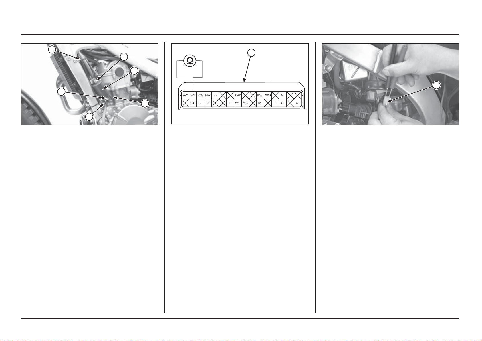
If the resistance is out of specification, measure the
resistance at the ignition pulse generator 2P (Natural)
connector.
If the measured resistance at ECM 32P (Black) connector
is incorrect and the ignition pulse generator 2P (Natural)
connector is correct, check the wire harness.
If the resistance is still out of standard, replace the ignition
pulse generator/stator assembly (page 4-52)
(1) 2P (NATURAL) CONNECTOR
Ignition Pulse Generator Inspection
Check the ignition coil resistance at the ECM 32P (Black)
connector (page 6-5).
Connection: White/yellow – Green/yellow
Standard: 85 - 115 (20˚C/68˚F)
(1) 32P (BLACK) CONNECTOR(1) WIRE CLAMP
(2) PRIMARY WIRES
(3) BOLTS
(4) IGNITION COIL
Remove the wire clamp.
Disconnect the primary wire from the ignition coil.
Remove the mounting bolts and ignition coil.
Installation is in the reverse order of removal.
Route the spark plug wire properly and secure it with tie
wrap.
1
4
3
3
2
2
1
1
Loading ...
Loading ...
Loading ...