Loading ...
Loading ...
Loading ...
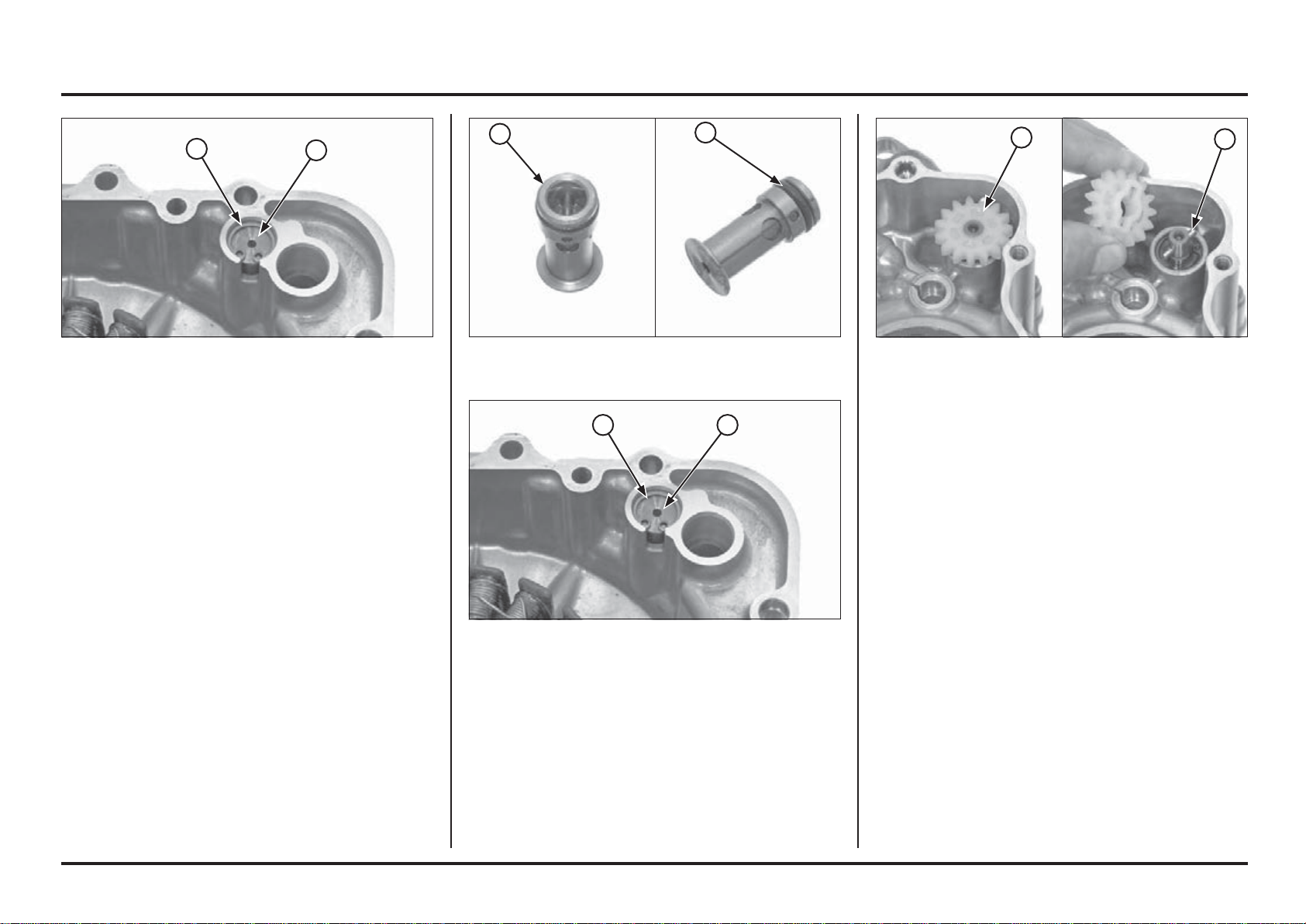
(1) SNAP RING
(2) PRESSURE RELIEF VALVE
(1) RELIEF VALVE
(2) O-RING
(1) DRIVEN GEAR
(2) DRIVE PIN
Oil Pressure Relief Valve
Removal/Inspection
Drain the engine oil.
Remove the left crankcase cover (page 4-49).
Remove the snap ring.
Remove the pressure relief valve from the left crankcase
cover.
(1) PRESSURE RELIEF VALVE
(2) SNAP RING
Check the relief valve operation by pushing the relief
valve piston.
Installation
Apply oil to a new O-ring and install it onto the relief valve
groove.
Install the relief valve into the left crankcase cover.
Install the snap ring into the crankcase cover groove
securely.
Install the left crankcase cover (page 4-51).
Oil Pump
Disassembly
Remove the engine from the frame.
Separate the crankcase halves (page 4-54).
Remove the oil pump driven gear and drive pin.
4. Engine servicing
4-1
4-1
2
1
2
1
2
1
2 1
Loading ...
Loading ...
Loading ...