Loading ...
Loading ...
Loading ...
6. NetCommand 51
An IR emitter cable is included with LT-40134, LT-46144, and
LT-52144 TV models only.
The NetCommand system uses emitters connected to
the IR EMITTER jack to control other devices such as
DVD players, cable boxes, satellite receivers, and VCRs.
1. Connect the plug end of the supplied IR emitter
cable to the IR EMITTER NetCommand ®jack on the
TV back panel #2 (in recessed area).
2. Run the cable for each of the emitter ends under,
alongside, or over each device to be controlled so
that the emitter end is in front of the area where the
remote control sensor is located.
3_
Position the emitter end with the emitter bulb facing
the remote control sensor. The bulb emits infrared
light in a cone-shaped pattern. Place the bulb far
enough from the sensor to allow the cone pattern
to reach the sensor.
The IR sensor is usually behind the plastic window
of the front display panel. It is sometimes visible
with the aid of a flashlight and is normally a round
or square cutout behind the plastic. If you cannot
see the sensor and the device's Owner's Guide
does not specify the location, you can find it by
following these steps using the device's remote
control:
a. Hold the device's remote about one-half inch
from the front of the device. Starting from one
end of the display window plastic, press the
POWERbutton.
b. If the device does not respond, move the
remote control one inch toward the center and
try again.
c. Repeat this until the device responds.
d. Note this location and then start over from the
other end of the display window plastic, repeat-
ing until the device responds again.
The remote control sensor is somewhere
between these two positions. This is usually
enough accuracy for placement of the IR emit-
ters.
With some devices, the emitter works better
facing downward from the top of the device.
Experiment to find what works best.
4. Secure the emitter ends in place using double-
sided tape.
5. Place any unused ends behind the devices to
prevent stray signals from reaching the IR sensors.
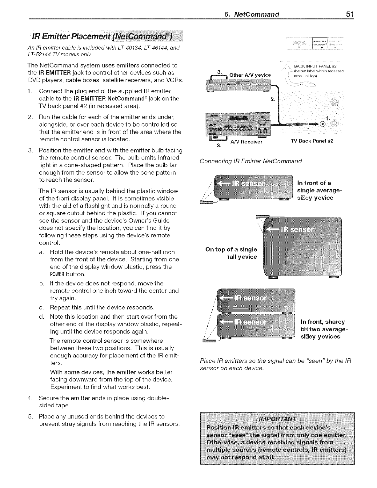
Other A/V yevice
BACK INPUT PANEL #2
below laDel wllnln recessec
area - al IOD_
91"
A/V Receiver
3.
TV Back Panel #2
Connecting IR Emitter NetCommand
in front of a
single average=
,".'"" si_ey yevice
On top of a single
tall yevice
i
i
1I
,, in front, sharey
," ,' b_ two average=
, , si_ey yevices
Place IR emitters so the signal can be "seen" by the IR
sensor on each device.
Loading ...
Loading ...
Loading ...