Loading ...
Loading ...
Loading ...
ASSEMBLY INSTRUCTIONS
ASSEMBLY OF SNOW BLADE TO
MODEL NO. 536 TRACTORS
Use all parts packed loose in Carton, and all
parts in Bag (A) and Bag (D).
Discard Carton (B), Bag (C) and Bag (E).
Not all parts in Hardware Package will be
used.
NOTE: To provide adequate clearance underneath this
model tractor, it will be necessary to reverse the
arrangement of the frame assembly. Refer to the
following instructions.
O
Remove the four bolts fastening the pivot support plate
to the frame assembly. Turn the frame assembly upside
down and refasten the pivot support plate using the
original bolts, lock washers and lock nuts. See figure 13.
0'
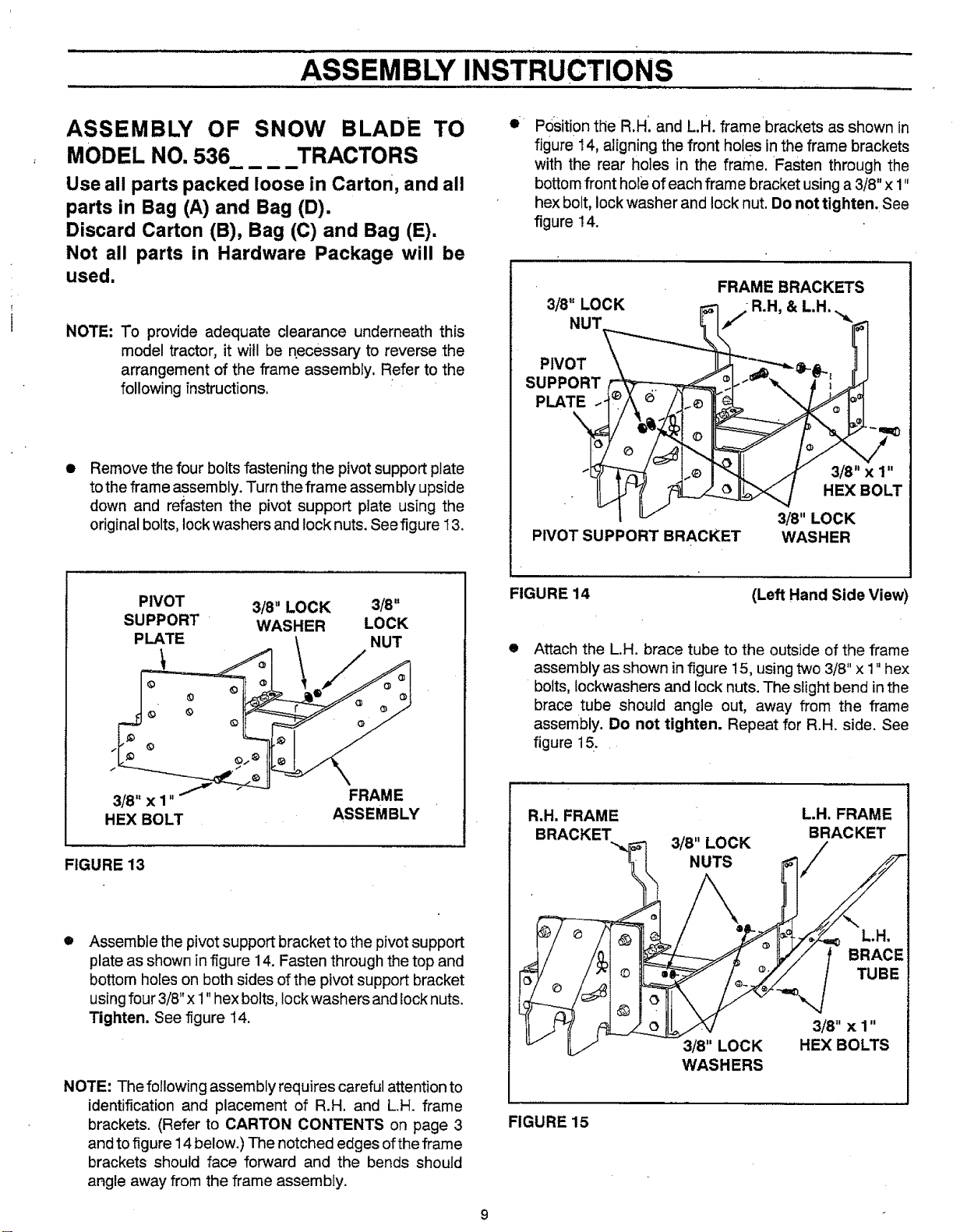
Position tlie R.H'. and L.H. frame brackets as shown in
figure ! 4, aligning the front holes in the frame brackets
with the rear holes in the frame. Fasten through the
bottom front hole of each frame bracket using a 3/8"x 1"
hex bolt, lock washer and lock nut. Do not tighten. See
figure !4.
3/8" LOCK
NUT
PIVOT
SUPPORT _ _
PLATE ..._ _)
PIVOT SUPPORT BRACKET
FRAME BRACKETS
i R.H, & LH.
HEX BOLT
3/8" LOCK
WASHER
PIVOT 3/8" LOCK 3/8"
SUPPORT WASHER LOCK
PLATE NUT
/
3/8" x 1" FRAME
HEX BOLT ASSEMBLY
FIGURE 13
O
Assemble the pivotsupport bracket to the pivot support
plate as shown in figure 14. Fasten through the top and
bottom holes on both sides of the pivot support bracket
using four 3/8" x 1" hex bolts, lock washers and lock nuts.
Tighten. See figure 14.
NOTE: The following assembly requires careful attention to
identification and placement of R.H. and L.H. frame
brackets. (Refer to CARTON CONTENTS on page 3
and to figure 14 below.) The notched edges of the frame
brackets should face forward and the bends should
angle away from the frame assembly.
FIGURE 14
(Left Hand Side View)
Attach the L.H. brace tube to the outside of the frame
assembly as shown infigure 15, using two 3/8" x 1" hex
bolts, lockwashers and lock nuts. The slight bend in the
brace tube should angle out, away from the frame
assembly. Do not tighten. Repeat for R.H. side. See
figure 15.
R.H. FRAME L.H. FRAME
BRACKET 3/8" LOCK BRACKET
NUTS
L.H,
3/8" LOCK
WASHERS
TUBE
3/8" X 1"
HEX BOLTS
FIGURE 15
Loading ...
Loading ...
Loading ...