Loading ...
Loading ...
Loading ...
ASSEMBLY INSTRUCTIONS
e
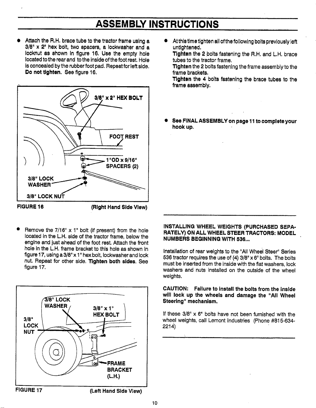
Attach the R,H, brace tube to the tractor frame using a
3/8" x 2" hex bolt, two spacers, a lockwasher and a
Iocknut as shown in figure 16, Use the empty hole
locatedtothe rear and tothe inside ofthefoot rest, Hole
isconcealed bythe rubberfoot pad. Repeat for leftside,
Do not tighten, See figure !6,
3/8" LOCK NUT
I I IIIIIIIII II I
FIGURE 16
8/8" x 2" HEX BOLT
f-------
REST
9/I 6"
' ___PACERS (2)
i , ..............
(Right Hand Side View)
e
At thistimetightenallofthe followingboltspreviouslyleft
untlghtened,
Tighten the 2 boltsfastening the R,H, and L.H. brace
tubesto the tractorframe,
Tighten the2 boltsfasteningtheframeassemblytothe
framebrackets,
Tighten the 4 boltsfastening the bracetubes to the
frameassembly,
• See FINAL ASSEMBLY on page 11 to complete your
hook up.
O
Remove the 7/16" x 1" bolt (if present) from the hole
located in the L.H. side of the tractor frame, below the
engine and just ahead of the foot rest, Attach the front
hole In the L.H, frame bracket to this hole as shown in
figure 17, using a 3/8" x 1" hex bolt, Iockwasher and lock
nut. Repeat for other side. Tighten both sides. See
figure 17.
3/8"
LOCK
NUT
LOCK
% 3/8" X 1"
HEX BOLT
BRACKET
(L.H.)
FIGURE 17
(Left Hand Side View)
INSTALLING WHEEL WEIGHTS (PURCHASED SEPA-
RATELY) ON ALL WHEEL STEER TRACTORS: MODEL
NUMBERS BEGINNING WITH 536,..
Installation of rear weights to the "All Wheel Steer" Series
536 tractor requires the use of (4) 3/8" x 6"bolts. The bofts
must be inserted from the inside with the flatwashers, lock
washers and nuts installed on the outside of the wheel
weights,
CAUTION: Failure to install the bolts from the inside
will lock up the wheels and damage the "All Wheel
Steering" mechanism.
If these 3/8" x 6" bolts have not been furnished with the
wheel weights, call Lemont industries (Phone #815-634-
2214)
10
Loading ...
Loading ...
Loading ...