Loading ...
Loading ...
Loading ...
ASSEMBLY INSTRUCTIONS
......... _- iiii |_ .............. r' _ i ,,,,, ,=, ,,r I
FINAL ASSEMBLY
O
Assemble the two angie look bars together as shown in
figure 18, so that all holes are aligned, Use one 3/8" x 1-
1/4" carriage bolt, one 8/8" look washer and one 3/8" hex
lock nut, Be sure to Insert boltfrom side Indicated, Do
not tighten at this time, See figure 18,
mM' l= =1
3/8" HEX NUT
3/8" LOCK WASHER
3/8" CARRIAGE BOLT
BRACKET (A)
LOCK SPRING
ANGLE
BARS FRONT--_
FIGURE18 (RlghtHandSideVtew
O
O
Hold the angle lock bars so that the square holes are at
the top_Hold the angle lock spring so that the opening of
the round hook isfacing up, Insert the straight hook end
of the spring through the middle hole In both angle lock
bars as shown Enfigure 18.
Assemble round hook end of angle lock spring up
through the hole inbracket (A), which is mounted on the
pivot bracket. See figures 18 and 19.
Pull on angle lock bars to extend spring just enough to
allow insertion of bars down through slot in channel and
.pivot bracket. Using a 1/4" x 3-1/4" bolt, two 1" Iong
spacers and a 1/4" lock nut, align the two spacers
underneath the channel on both sides of the angle lock
bars and insert the bolt through holes in sides of the
channel and through the angle lock bars and the two
spacers, Assemble the lock nut to the bolt on outside of
channel, Tighten so that lock bars pivot freely. See figure
19,
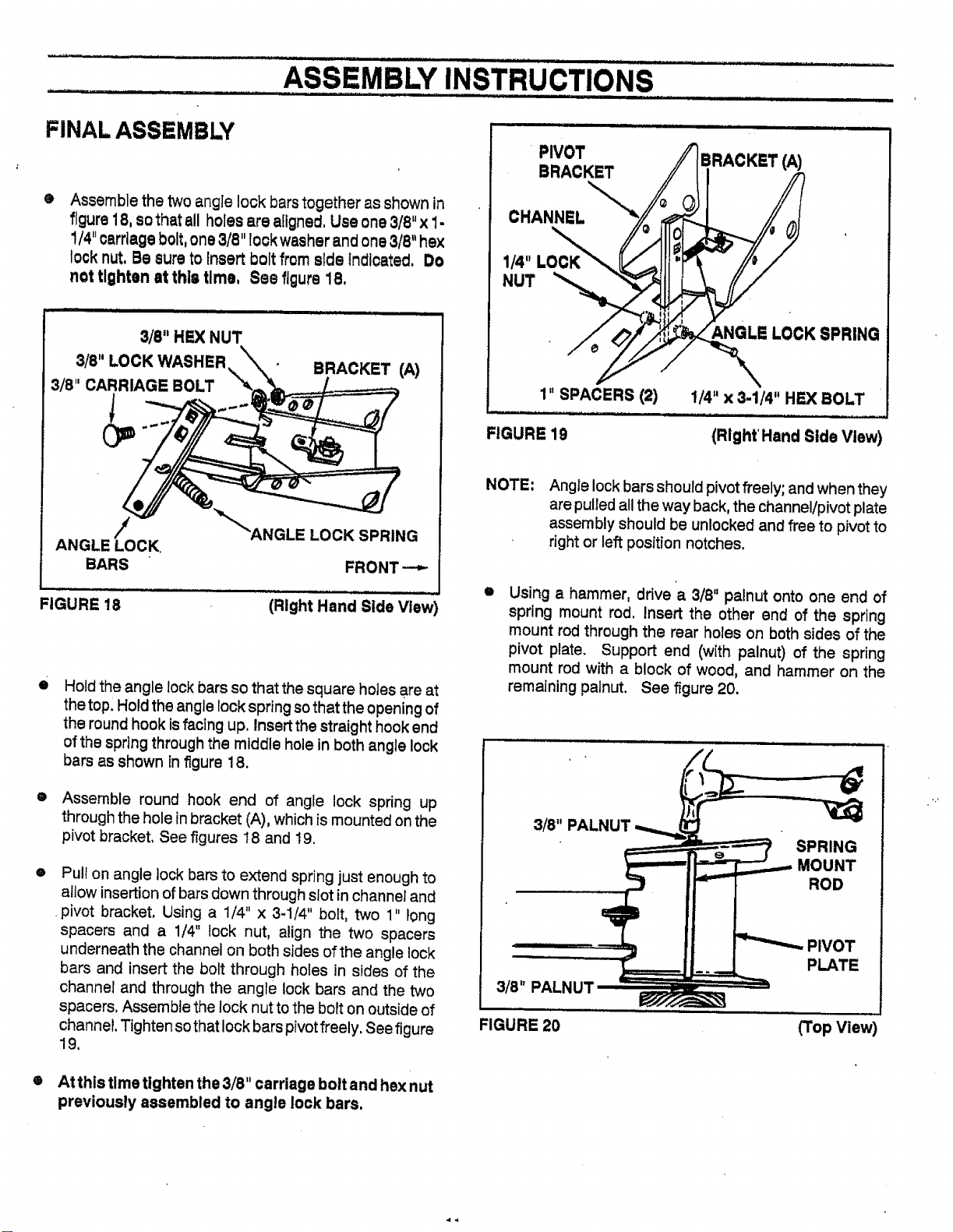
PIVOT
BRACKET
BRACKET (A)
CHANNEL
I_"LOCK
NUT
6,NGLELOCKSPRING
1" SPACERS (2) 1/4"x 3-1/4" HEX BOLT
FIGURE 19 (Right' Hand Side View)
NOTE:
Angle lock bars should pivot freely; and when they
are pulled all the way back, the channel/pivot plate
assembly should be unlocked and free to pivot to
right or left position notches.
O
Using a hammer, drive a 3/8" palnut onto one end of
spring mount rod, Insert the other end of the spring
mount rod through the rear holes on both sides of the
pivot plate. Support end ('with palnut) of the spring
mount rod with a block of wood, and hammer on the
remaining palnut. See f_gure 20.
3/8" PALNUT
SPRING
MOUNT
ROD
3/8" PALNU1
FIGURE 20
(Top View
• At this time tighten the 3/8" carriage bolt and hex nut
previously assembled to angle lock bars,
Loading ...
Loading ...
Loading ...