Loading ...
Loading ...
Loading ...
ASSEMBLY INSTRUCTIONS
@
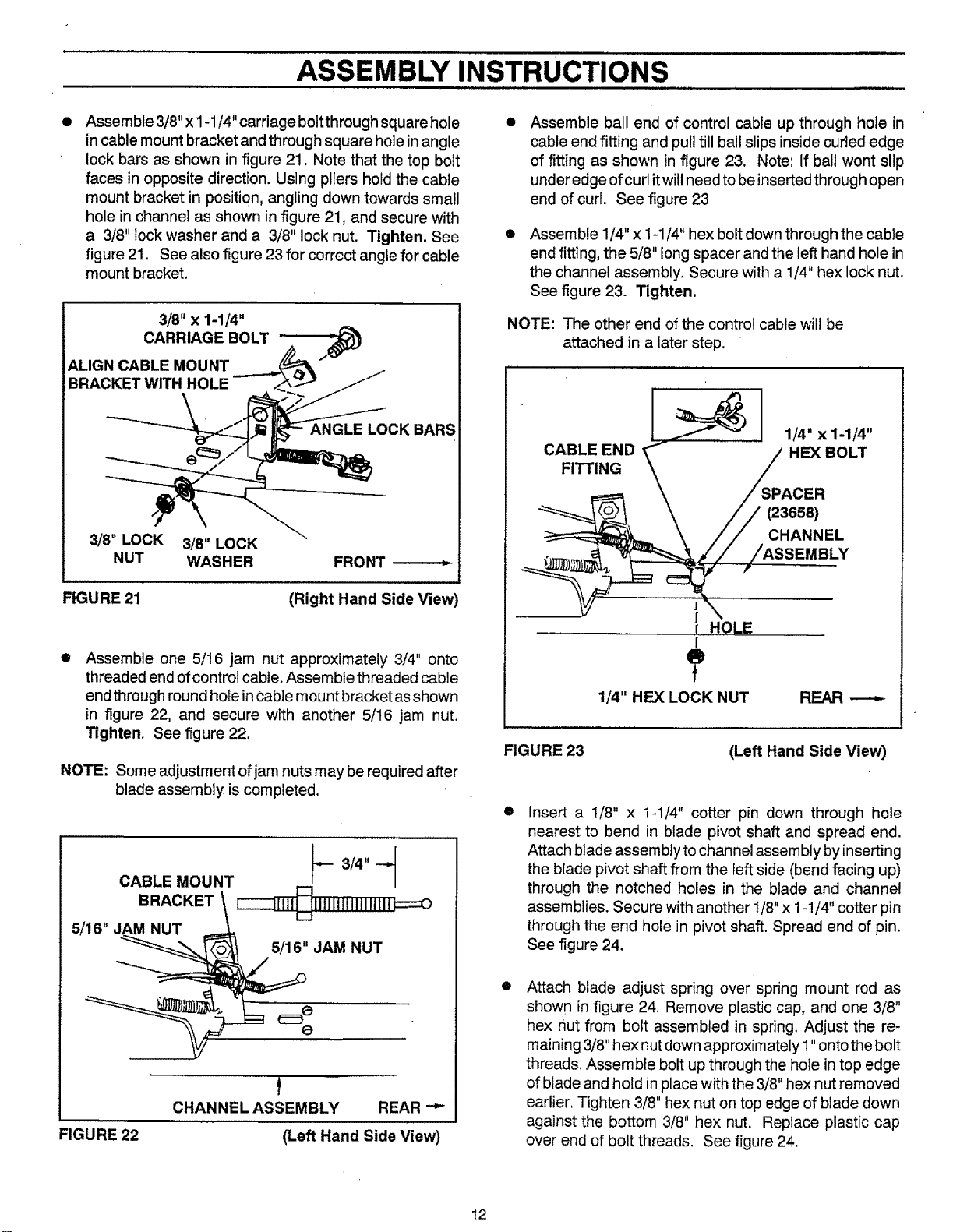
Assemble 3/8" x 1-1/4" carriage bolt through square hole
in cable mount bracket and through square hole in angle
lock bars as shown in figure 21. Note that the top bolt
faces in opposite direction. Using pliers hold the cable
mount bracket in position, angling down towards small
hole in channel as shown in figure 21, and secure with
a 3/8" lock washer and a 3/8" lock nut, Tighten. See
figure 21. See also figure 23 for correct angle for cable
mount bracket.
3/8" x 1-1/4"
CARRIAGE BOLT
ALIGN CABLE MOUNT
BRACKET WITH HOLE
ANGLE LOCK BARS
3/8" LOCK 3/8" LOCK
NUT WASHER FRONT
FIGURE 21
(Right Hand Side View
@
Assemble one 5/16 jam nut approximately 3/4" onto
threaded end of control cable. Assemble threaded cable
end through round hole in Cablemount bracket asshown
in figure 22, and secure with another 5/16 jam nut.
Tighten. See figure 22.
NOTE: Some adjustment of jam nuts may be required after
blade assembly is completed.
CABLE MOUNT _-- 3/4" -_
BRACKET _ _[111 o_[]TITFg]TmTN==o
5/16" J_,M NUT _=._ ,,
__ _ 5/16 JAM NUT
FIGURE 22
t
CHANNEL ASSEMBLY REAR "_
(Left Hand Side View)
@
O
Assemble ball end of control cable up through hole in
cable end fitting and pull till ball slips inside curled edge
of fitting as shown in figure 23. Note: If bail wont slip
under edge of Curlitwill need to be insertedthrough open
end of curl. See figure 23
Assemble 1/4" x 1-1/4" hex bolt down through the cable
end fitting, the 5/8" long spacer and the left hand hole in
the channel assembly. Secure with a 1/4" hex lock nut,
See figure 23. Tighten.
NOTE: The other end of the control cable will be
attached in a later step.
FIGURE 23
CABLE END
FITTING
1/4" x 1-1/4"
HEX BOLT
SPACER
_365_
CHANNEL
;SEMBLY
J
HOLE
[
?
1/4" HEX LOCK NUT REAR ---_
@
(Left Hand Side View)
@
Insert a 1/8" x 1-1/4" cotter pin down through hole
nearest to bend in blade pivot shaft and spread end.
Attach blade assembly to channel assembly by inserting
the blade pivot shaft from the left side (bend facing up)
through the notched holes in the blade and channel
assemblies. Secure with another 1/8" x 1-!/4" cotter pin
through the end hole in pivot shaft. Spread end of pin.
See figure 24.
Attach blade adjust spring over spring mount rod as
shown in figure 24. Remove plastic cap, and one 3/8"
hex nut from bolt assembled in spring. Adjust the re-
maining 3/8" hex nut downapproximate[y I "onto the bolt
threads, Assemble bolt up through the hole in top edge
of blade and hold in place with the 3/8" hex nut removed
earlier. Tighten 3/8" hex nut on top edge of blade down
against the bottom 3/8" hex nut. Replace plastic cap
over end of bolt threads. See figure 24.
12
Loading ...
Loading ...
Loading ...