Loading ...
Loading ...
Loading ...
ASSEMBLY INSTRUCTIONS
1/8" x 1.1/4"
COTTER PIN--
BLADE _/.
PIVOT _
SHAFT I
L
SHOE
CHANNEL
ASS'Y
flop)
_ 3/8" HEX NUT PLASTIC
CAP
1
3/8" HEX NUT
I (BOTTOM)
\
BLADE
ASS'Y
BLADE ADJUST
SPRING
SPRING 1/8" x 1-1/4"
MOUNT ROD COTTER PIN
FIGURE 24
(Right Hand Side View)
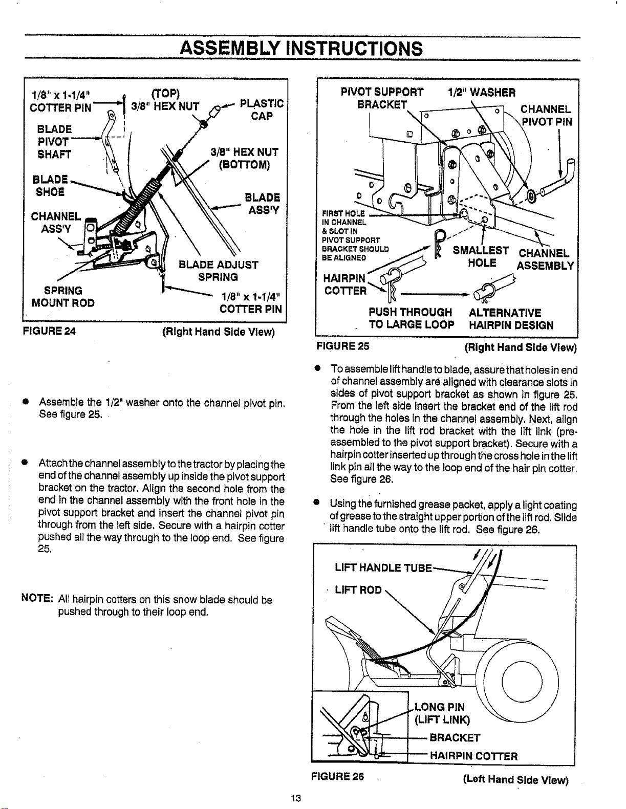
• Assemble the 1/2" washer onto the channel pivot pfn,
See figure 25.
®
Attach the channel assembly to the tractor by placing the
end of the channel assembly up inside the pivot support
bracket on the tractor, Align the second hole from the
end in the channel assembly with the front hole in the
pivot support bracket and insert the channel pivot pin
through from the _eftside. Secure with a hairpin cotter
pushed all the way through to the loop end. See figure
25.
NOTE: All hairpin cotters on this snow blade should be
pushed through to their loop end.
13
PIVOT SUPPORT
BRACKET
1/2" WASHER
0
FIRST HOLE _,._J_
IN CHANNEL
& SLOT _N _ ""
PIVOT SUPPORT " "" _"
BRACKET SHOULD / _" SMALLEST CHANNEL
BE ALIGNED f._ HOLE
ASSEMBLY
COTTER *_
PUSH THROUGH ALTERNATIVE
TO LARGE LOOP HAIRPIN DESIGN
FIGURE 25
(Right Hand Side View)
o
To assemble lift handle to blade, assure that holes inend
of channel assembly are aligned with clearance slots in
stdes of pivot support bracket as shown tn figure 25.
From the left side insert the bracket end of the flff rod
through the holes In the channel assembly. Next, atlgn
the hole in the lift rod bracket with the lift link (pre-
assembled to the pivot support bracket). Secure with a
hairpin cotter inserted up through the cross hole inthe lift
link pin aJIthe way to the loop end of the hair pin cotter.
See figure 26.
O
Using the furnished grease packet, apply a light coating
of grease to the straight upper portion of the lift rod. Slide
lift handle tube onto the lift rod. See figure 26.
FIGURE 26
3KET
IN co'rrER
(Left Hand Side View)
Loading ...
Loading ...
Loading ...