Loading ...
Loading ...
Loading ...
ASSEMBLY INSTRUCTIONS
TOOLS REQUIRED FOR ASSEMBLY
(1)
(1)
(1)
(1)
(1)
(1)
Pliers
Hammer
Adjustable Wrench (or socket set)
9/16" Open End or Box EndWrench
7/16" Open End or Box End Wrench
1/2" Open End or Box End Wrench
Parts Baa Usaae:
You will use the following enclosed
bags based on the first 3 digits of your
TRACTOR model number.
Model No. Parts Bags Used
502 A, C, D and E Only
536 A and D Only
917 A, B and C Only
DISCARD UNUSED BAGS.
REMOVAL OF PARTS FROM CARTON
• Refer to carton contents on page 3 and figure I on page
4 for parts and hardware needed to assemble snow
blade.
NOTE: Right hand (R.H.) and left hand (L.H,) are deter-
mined from the operators position while seated on
the tractor.
TRACTOR PREPARATION
• Remove mower deck or any other attachment you may
have mounted to your tractor. Mark all loose parts and
save for re-assembly. Refer to owners manual for
removal of mower/attachment.
ASSEMBLY OF SNOW BLADE TO
MODEL NO. 917 TRACTORS
Use all parts packed loose in Carton, and all
parts in Bag (A), Carton (B) and Bag (C).
Discard Bag (D) and Bag (E).
Not all parts in Hardware Package will be
used.
O
Using the two bottom holes, attach the pivot support
bracket to the front of the frame assembly using two
3/8" x 1" hex bolts, Iockwashers and lock nuts. See
figure 2. Do not tighten till next step.
®
Using the two top holes assemble the pivot plate bracket
to the front (inside) of the frame assembly using two
3/8" x 1-1/4" hex bolts, Iockwashers and lock nuts. See
figure 2. Tighten all loose bolts.
5
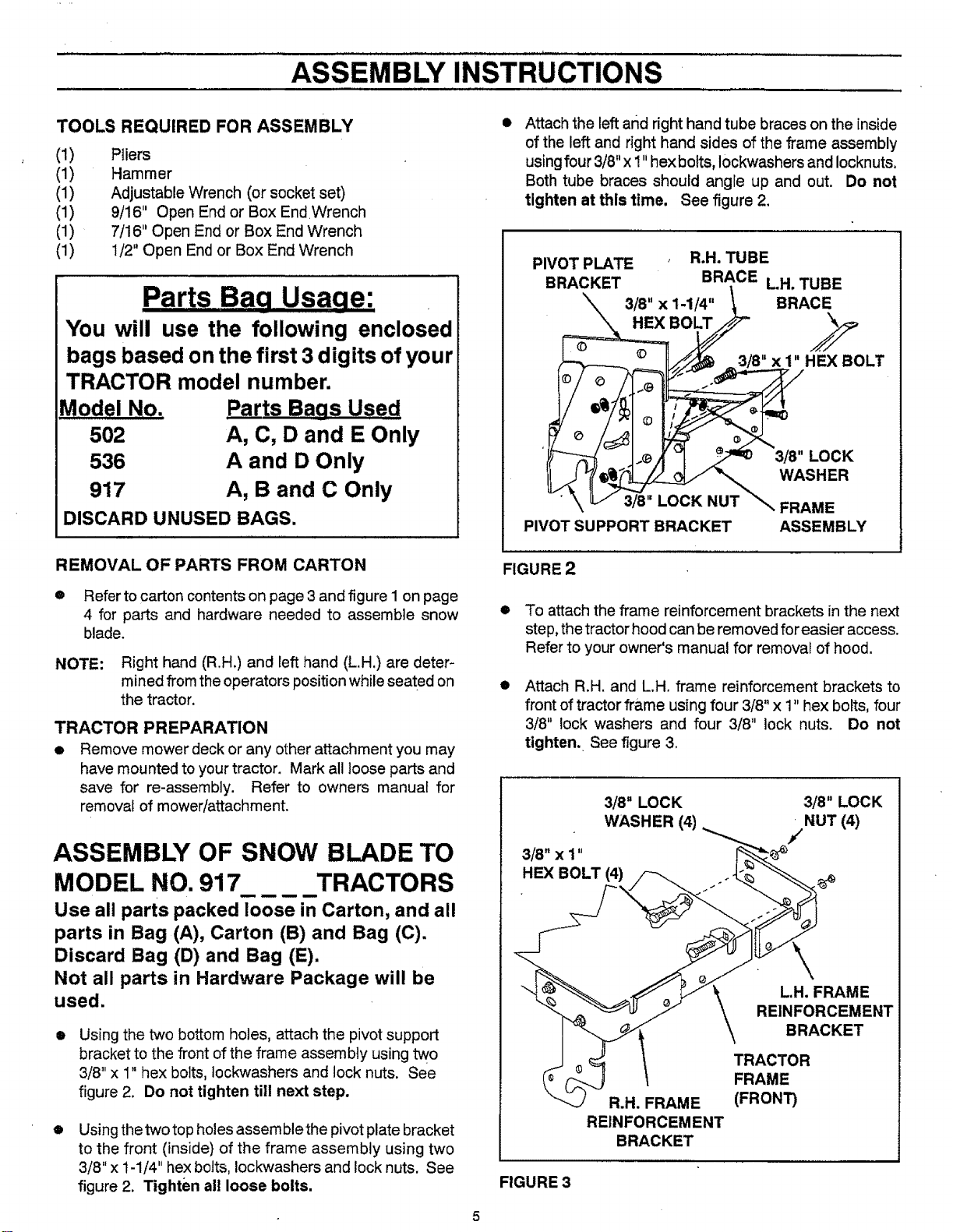
O
Attach the left and right hand tube braces on the inside
of the left and right hand sides of the frame assembly
using four 3/8"x 1" hex bolts, Iockwashers and Iocknuts.
Both tube braces should angle up and out. Do not
tighten at this time. See figure 2,
PIVOT PLATE R.H. TUBE
BRACKET BRACE LH. TUBE
\ 3/8"x1.1/4,, BRACE
'}['_-_ _ .J._/_'q _ 3/8" LOCK
" \ v 3/8" LOCK NUT _,, FRAME
PIVOT SUPPORT BRACKET ASSEMBLY
FIGURE 2
• To attach the frame reinforcement brackets in the next
step, the tractor hood can be removed for easier access.
Refer to your owner's manual for removal of hood.
O
Attach R.H. and L.H. frame reinforcement brackets to
front of tractor frame using four 3/8" x 1" hex bolts, four
3/8" lock washers and four 3/8" lock nuts. Do not
tighten. See figure 3.
3/8" LOCK 3/8" LOCK
WASHER (4) = NUT (4)
3/8"xi" "__
/
HEX BOLT =(4)/_ .-L_ _
_ REII"iF:OARcCKA_I:ENT
ACTOR
(_ _ \ FRAME
R.H. FRAME (FRONT)
REINFORCEMENT
BRACKET
FIGURE 3
Loading ...
Loading ...
Loading ...