Loading ...
Loading ...
Loading ...
32
EXTERNAL ALARM DEVICE CONNECTION
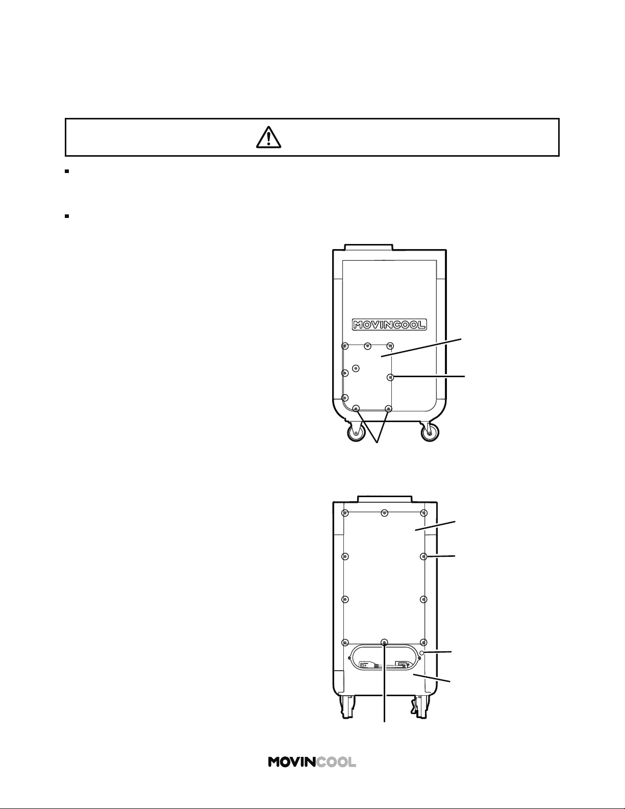
1. Turn the unit o and unplug the power cord.
2. Loosen the bo om two (2) screws and take out
the other seven (7) screws. Move the service
panel upward and remove it from the side of
the unit.
The terminal block has two sets of input signal terminals for external alarm devices such as a fi re
alarm. The terminals should only be connected to a closed or an open dry contact. When receiving
the signals from the external alarm devices, the unit turns itself o and cannot be turned back on
until it has been reset.
3. Loosen the center bo om screw and take out
the other nine (9) screws. Move the upper rear
panel upward and remove it.
4. Squeeze the inner latch and push out the cap
from inside the lower rear panel.
WARNING
Installation and electrical work must be performed in accordance with national wiring
regulations by qualified personnel. Incorrect installation may cause fire, electric shock,
injury, malfunction or water leaks.
Disconnect power before installation. Beware that some residual voltage may remain in the
unit after the power is disconnected. There is a risk of electric shock.
Take out screws (7)
Service Panel
Loosen screws (2)
Loosen screw (1)
Lower Rear Panel
Cap (a hole for wires)
Take out screws (9)
Upper Rear Panel
Loading ...
Loading ...
Loading ...