Loading ...
Loading ...
Loading ...
30
EXTERNAL WARNING DEVICE CONNECTION
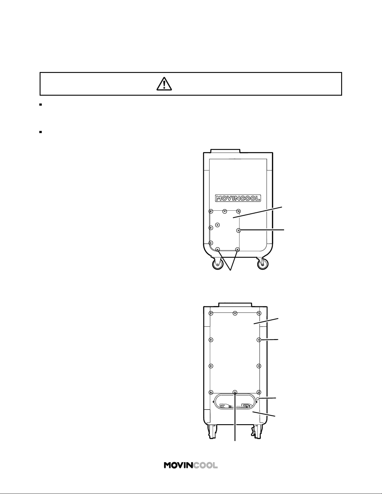
1. Turn the unit o and unplug the power cord.
2. Loosen the bo om two (2) screws and take out
the other seven (7) screws. Move the service
panel upward and remove it from the side of
the unit.
The controller has a warning signal output relay which can indicate failure of the unit with external
warning devices such as alarm speaker or light indicators.
Relay type: Form C, normal open dry contact
Relay output contactor rating: 2 A at 30 V (DC/AC) or less (resistive load)
3. Loosen the center bo om screw and take out
the other nine (9) screws. Move the upper rear
panel upward and remove it.
4. Squeeze the inner latch and push out the cap
from inside the lower rear panel.
WARNING
Installation and electrical work must be performed in accordance with national wiring
regulations by qualified personnel. Incorrect installation may cause fire, electric shock,
injury, malfunction or water leaks.
Disconnect power before installation. Beware that some residual voltage may remain in the
unit a er the power is disconnected. There is a risk of electric shock.
Take out screws (7)
Service Panel
Loosen screws (2)
Loosen screw (1)
Lower Rear Panel
Cap (a hole for wires)
Take out screws (9)
Upper Rear Panel
Loading ...
Loading ...
Loading ...