Loading ...
Loading ...
Loading ...
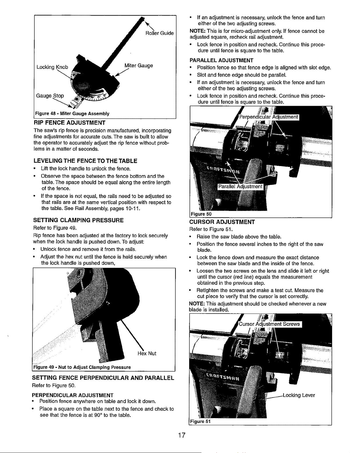
Roller Guide
Locking Miter Gauge
Figure 48 - Miter Gauge Assembly
RIP FENCE ADJUSTMENT
The saw's rip fence is precision manufactured, incorporating
fine adjustments for accurate cuts. The saw is built to allow
the operator to accurately adjust the rip fence without prob-
lems in a matter of seconds.
LEVELING THE FENCE TO THE TABLE
• Lift the lock handle to unlock the fence.
• Observe the space between the fence bottom and the
table. The space should be equal along the entire length
of the fence.
• If the space is not equal, the rails need to be adjusted so
that rails are at the same vertical position with respect to
the table. See Rail Assembly, pages 10-11.
SETTING CLAMPING PRESSURE
Refer to Figure 49.
Rip fence has been adjusted at the factory to locksecurely
when the lock handle is pusheddown. To adjust:
* Unlockfence and removeit fromthe rails.
° Adjust the hex nut untilthe fence is held securelywhen
the lockhandle is pushed down,
Hex Nut
SETTING FENCE PERPENDICULAR AND PARALLEL
Refer to Figure 50.
PERPENDICULAR ADJUSTMENT
• Position fence anywhere on table and lock it down.
° Place a square on the table next to the fence and check to
see that the fence is at 90 ° to the table.
° If an adjustment is necessary, unlock the fence and turn
either of the two adjusting screws.
NOTE: This is for micro-adjustment only. If fence cannot be
adjusted square, recheck rail adjustment.
° Lock fence in position and recheck. Continue this proce-
dure until fence is square to the table.
PARALLEL ADJUSTMENT
• Position fence so that fence edge is aligned with slot edge.
• Slot and fence edge should be paralIel.
• If an adjustment is necessary, unlock the fence and turn
either of the two adjusting screws.
° Lock fence in position and recheck. Continue this proce-
dure until fence is square to the table.
Figure 50
CURSOR ADJUSTMENT
Refer to Figure 51.
• Raise the saw blade above the table.
• Position the fence several inches to the right of the saw
blade.
• Lock the fence down and measure the exact distance
between the saw blade and the inside of the fence.
• Loosen the two screws on the lens and slide it left or right
until the cursor (red line) equals the measurement
obtained in the previous step.
° Retighten the screws and make a test cut. Measure the
cut piece to verify that the cursor is set correctly.
NOTE: This adjustment should be checked whenever a new
blade is installed.
g Lever
Figure 51
17
Loading ...
Loading ...
Loading ...