Loading ...
Loading ...
Loading ...
BLADE TILT ADJUSTMENT
Refer to Figures 44 and 45, page 15 and 16.
• The saw blade can be set at any angle between 90 ° and
45 °. Blade tilt is controlled by the handwheel (Fig. 44) on
the right side of the saw. The indicator (Fig. 45) on front of
saw shows the tilt angle of the blade.
• To adjust tilt, loosen locking hand knob. Rotate knob coun-
terclockwise at least three turns. Turn handwheel to
desired blade angle. Lock blade angle into position.
• Lock handwheel by tightening locking hand knob clock-
wise. Tighten only until snug.
= The saw is equipped with positive stops at 90° and 45 °.
These positive stops aUow operator to position saw blade
at 90 ° and 45 ° quickly and accurately.
Figure 45 - Blade Tilt Handwheel
90 ° STOP ADJUSTMENT
Refer to Figures 44 and 46.
• Raise saw blade above table as far as possible. Set blade
at 90 ° to table by turning the tilting handwheel. Place a
square on table and check to see if blade is perpendicular
to the table. When checking put square flush against saw
blade. Do not put square on teeth of saw blade.
• If the blade will not tilt to 90°, turn (counterclockwise) the
set screw at the left front of the table insert until the blade
can be positioned to 90 °.
• Once the blade has been tilted to 90 ° (confirm this using
your square), tighten the bevel handwheel lock knob,
located on the side of the cabinet. This will keep the blade
from tilting further.
• Turn the set screw (clockwise) until it comes in contact
with the positive stop.
• Check tilt indicator pointer. If necessary, adjust pointer so it
points to 0° mark on scale. To adjust pointer, remove
handwheel and loosen screw on pointer. Be sure to tight-
en screw securely after adjustment is completed.
Figure 46 - Table Insert
45 ° STOP ADJUSTMENT
Refer to Figure 46.
• Tilt the saw blade to 45°. Usinga combinationsquare,
checkto see if blade is 45° to the table.
• If the bladewillnot tiltto 45°, turn (counterclockwise) the
set screw locatedat the rightof the table insert, untilthe
blade can be positionedto 45°.
• With the blade at 45°, tightenthe bevel handwheel lock
knob to keepthe blade from further tilting.
• Turnthe set screwclockwiseuntilit comesin contactwith
the positivestop.
TABLE INSERT ADJUSTMENT
Refer to Figure 46.
° The table insert must always be level with the saw table.
° Place a straight edge across the front and rear of the table
insert. Check that the insert is perfectly level with the saw
table.
• To level the table insert, turn one or more adjusting set
screws as needed and recheck.
° The table insert is equipped with two finger holes for easy
removal.
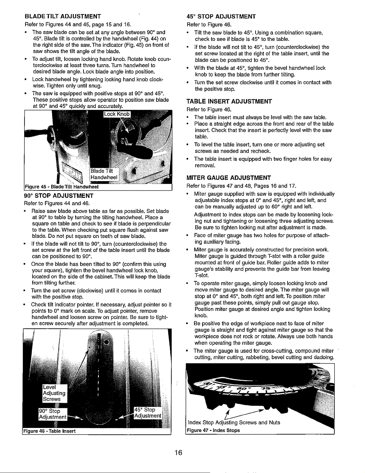
MITER GAUGE ADJUSTMENT
Refer to Figures 47 and 48, Pages 16 and 17.
° Miter gauge supplied with saw is equipped with individually
adjustable index stops at 0° and 45 °, right and left, and
can be manually adjusted up to 60 ° right and left.
Adjustment to index stops can be made by loosening lock-
ing nut and tightening or loosening three adjusting screws.
Be sure to tighten locking nut after adjustment is made.
• Face of miter gauge has two holes for purpose of attach-
ing auxiliary facing.
• Miter gauge is accurately constructed for precision work.
Miter gauge is guided through T-slot with a roller guide
mounted at front of guide bar. Roller guide adds to miter
gauge's stability and prevents the guide bar from leaving
T-slot.
• To operate miter gauge, simply loosen locking knob and
move miter gauge to desired angle. The miter gauge will
stop at 0° and 45 °, both right and left. To position miter
gauge past these points, simply pull out gauge stop.
Position miter gauge at desired angle and tighten locking
knob.
• Be positive the edge of workpiece next to face of miter
gauge is straight and tight against miter gauge so that the
workpiece does not rock or rotate. Always use both hands
when operating the miter gauge.
• The miter gauge is used for cross-cutting, compound miter
cutting, miter cutting, rabbeting, bevel cutting and dadoing.
Index Stop Adjusting Screws and Nuts
Figure 47 - Index Stops
16
Loading ...
Loading ...
Loading ...