
Loading ...
Loading ...
Loading ...
Rip Fence Assembly and Adjustment ...........................
i WARNING: To prevent personal injury, always dis- i
l connect plug from power source when making I
adjustments.
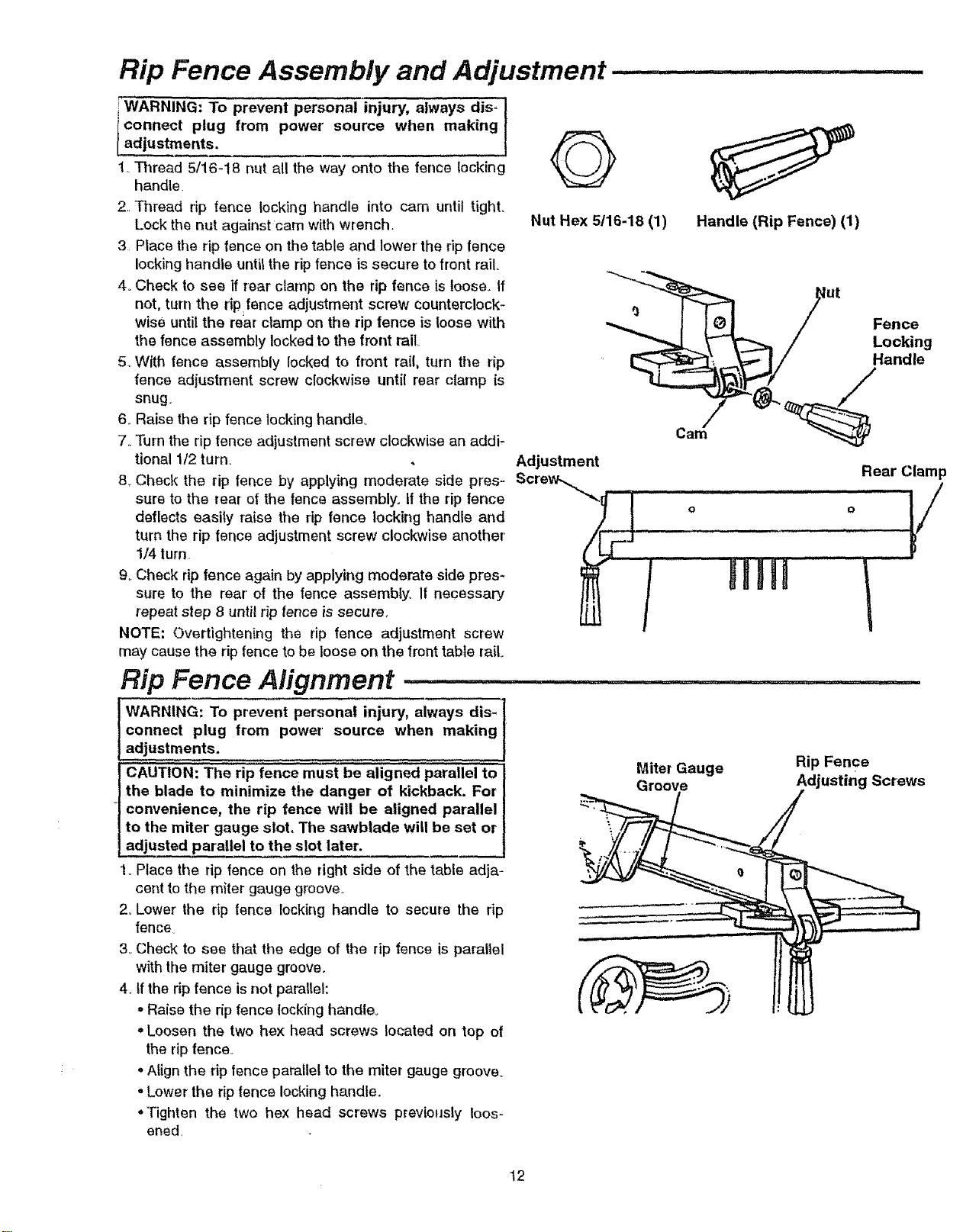
1. Thread 5/16-18 nut all the way onto the fence locking
handle
2, Thread rip fence locking handle into cam until tight,,
Lock the nut against cam with wrench,
3 Place the rip fence on the table and lower' the rip fence
locking handle until the rip fence is secure to front rail.
4. Check to see if rear' clamp on the rip fence is loose,. If
not, turn the rip fence adjustment screw counterclock-
wise until the rear clamp on the rip fence is loose with
the fence assembly locked to the front rail,
5, With fence assembly locked to front rail, turn the rip
fence adjustment screw clockwise until rear clamp is
snug.
6, Raise the rip fence lockinghandle.
7,.Turn the rip fence adjustment screw clockwise an addi-
tional 1/2 turn.
8. Check the rip fence by applying moderate side pres-
sure to the rear ef the fence assembly, If the rip fence
deflects easily raise the rip fence locking handle and
turn the rip fence adjustment screw clockwise another
1/4 turn.
9. Check rip fence again by applying moderate side pres-
sure to the rear of the fence assembly. If necessary
repeat step 8 until rip fence is secure.
NOTE: Overtightening the rip fence adjustment screw
may cause the rip fence to be loose on the front table rail.
Rip Fence Alignment ..................
j WARNING: To prevent personal injury, always dis- I
m
connect plug from power' source when making
adjustments.
i CAUTION: The rip fence must be aligned parallel to
I
'1the blade to minimize the danger of kickback. For }
} convenience, the rip fence will be aligned parallel
I to the miter gauge slot. The sawblade will be set or I
1adjus!ed parallel to the slot later. !
1,.Place the rip fence on the right side of the table adja-
cent to the miter gauge groove,.
2. Lower the rip fence locking handle to secure the rip
fence.
3. Check to see that the edge of the rip fence is parallel
with the miter gauge groove.
4. If the rip fence is not parallel:
oRaise the rip fence locking handle.
• Loosen the two hex head screws located on top of
the rip fence,.
oAlign the ripfence parallel to the miter gauge groove.
oLower the rip fence locking handle,,
•Tighten the two hex head screws previously loos-
ened,
Q
Nut Hex 5/16-18 (1)
Adjustment
Handle (Rip Fence) (1)
/
Miter Gauge
ut Fence
/ Locking
Rear Clamp
o
Rip Fence
Adjusting Screws
!2
Loading ...
Loading ...
Loading ...