Loading ...
Loading ...
Loading ...
TO REMOVE SNOW THROWER
FROM CARTON
• Locate and remove container of 5W30 oil.
• Locate all parts packed separately and
remove from the carton.
NOTE: Place fuel stabilizer in a safe place
untilneeded for storage.
• Remove and discard the packing material
from around the snow thrower.
• Gut all four comers of the carton from top
to bottom and lay the panels flat.
• Roll the snow thrower off the carton by
pulling on the lower handle. CAUTION:
DO NOT back over cables.
• Remove the packing material from
handle assembly and plastic protectoron
top of auger housing.
• Cut ties securing the clutch controlcables
tothe lower handle and lay cables back
away from the motor frame,
TO INSTALL THE UPPER HANDLE
AND CRANK ASSEMBLY
• Cut tie holdingshift rod to lower handle
and move shifterto the firstgear.
• Loosen, but do not remove the screws,
flatwashers, Iockwashers and hex nuts in
the upper holes ofthe lower handle. See
figure below.
Upper handle
Loosen do not
remove
11/32" Ratwasher
5/1
5/16 X 2,
5/16" Lockwasher
• Raise upper handle into operating posi-
tion. Upper handle should be tothe
outside ofthe lower handle.
NOTE: Make sure the cables are not caught
between the upper and lower handle.
NOTE: Ifthe cables have become discon-
nected from the clutchlevers, reinstallthe
cables as shown in figure below.
'Z_fitting
NOTE: Positioncable through slots on
shifterplate.
• Install hardware supplied in the pads bag
(Screw, tiatwasher, Iockwasher, and hex
nut) into middle hole on righthand side of
handles. Do not tighten untilall bolts are
in place.
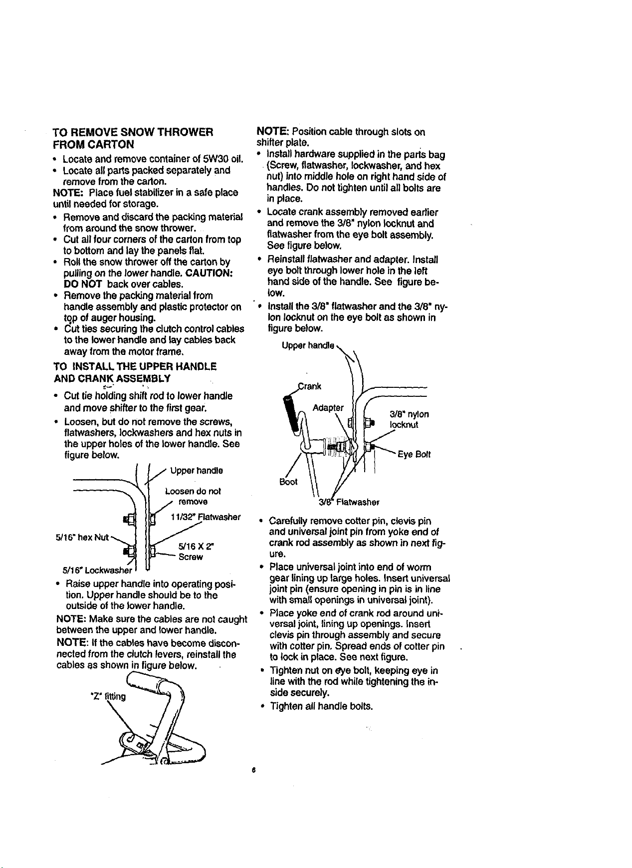
• Locate crank assembly removed earlier
and remove the 3/8' nylon Iocknut and
flatwasher from the eye bolt assembly.
See figure below.
• Reinstall flatwasher and adapter. Install
eye bolt through lower hole in the left
hand side of the handle. See figure be-
low.
"e
install the 3/8" flatwasher and the 3/8" ny-
lon Iocknut on the eye bolt as shown in
figure below.
3/8" nylon
Iocknut
e Bolt
Boot
• Carefully remove cotter pin, clevis pin
and universaljoint pinfrom yoke end of
crank rodassembly as shown in next fig-
ure.
• Place universaljoint into end ofworm
gear liningup large holes. Insert universal
jointpin (ensure opening in pin is in line
with small openings in universal joint).
• Place yoke end ofcrank rod around uni-
versal joint, lining up openings. Insert
clevis pin through assembly and secure
with cotter pin. Spread ends of cotter pin
to lock in place. See nextfigure.
• Tighten nut on eye bolt, keeping eye in
linewith the rod whiletightening the in-
side securely.
• Tighten all handle bolts.
Loading ...
Loading ...
Loading ...