
Loading ...
Loading ...
Loading ...
Step-by-step installation instructions.
::Ji::Turn off the gas or electric supply to the water heater) in the possibility
that the water heater may be drained while draining pipes.
::Ji::Turn off the water supply to pipes to be cut and drain the house
water pipes.
_: Open both hot and cold taucets at the lowest location possible.
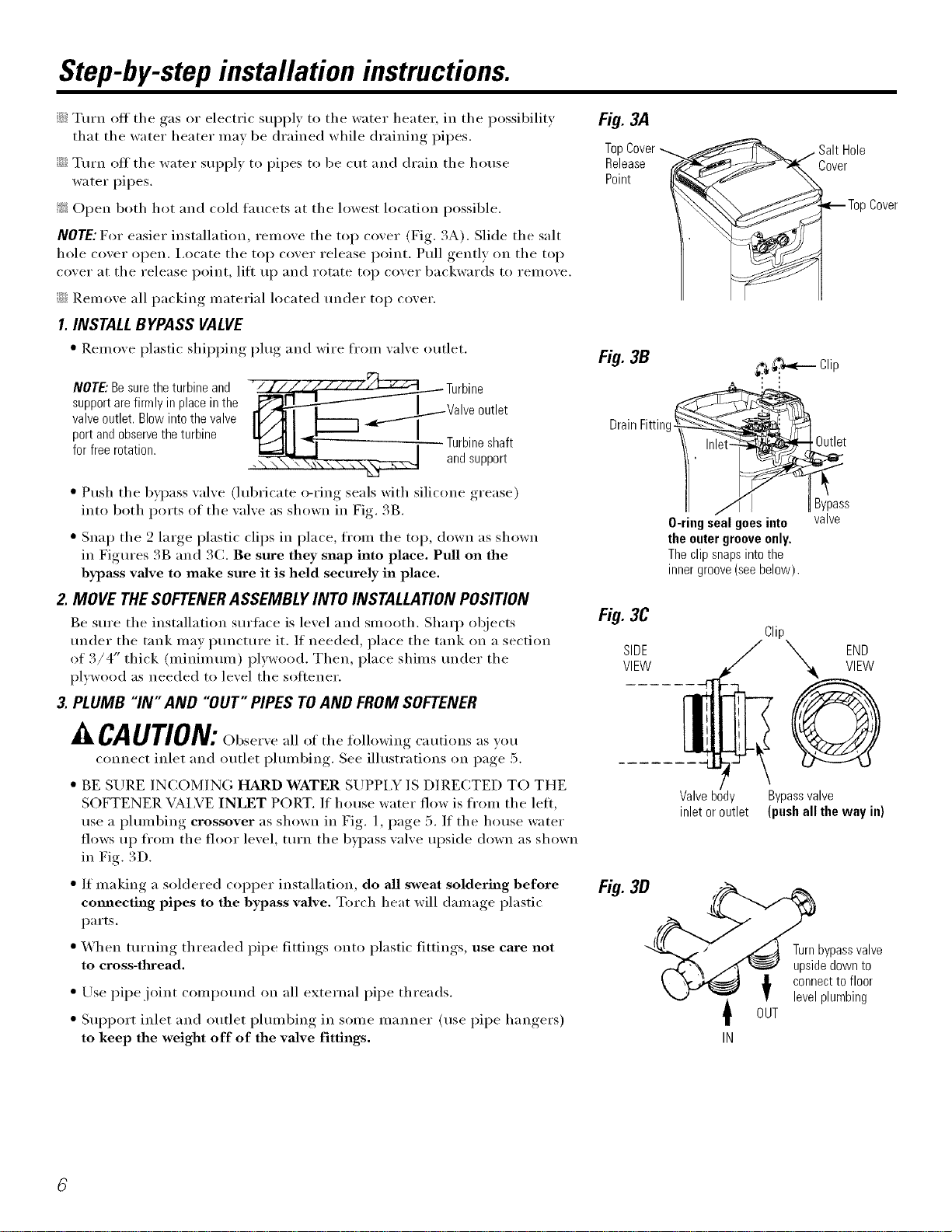
NOTE: For easier installation, remove the top cover (Fig. 3A). Slide the salt
hole cover open. i,ocate the top cover release point. Pull gently on the top
cover at the release point, lilt up and rotate top cover backwards to remove.
::Ji::Remove all packing material located under top cover.
1.INSTALL BYPASS VALVE
* Remove plastic shii_ping plug and wire ti'om valve outlet.
NOTE:Besuretheturbineand " " bv__
supportarefirralyin placeinthe __1 _u£1 utlet
valveoutlet. Blowinto thevalve _TaUn_lsn:p Sp_/
port andobservethe turbine
for freerotation, t
• Push the byl)ass valve (lubricate o-ring seals with silicone grease)
into both ports of the valve as shown in Fig. 3B.
• Snap the 2 large plastic clips in place, from the top, down as shown
in Figures 3B and 3(:. Be sure they snap into place. Pull on the
bypass valve to make sure it is held securely in place.
2. MOVE THE SOFTENERASSEMBLY INTO INSTALLATION POSITION
Be sure the installation surtace is level and smooth. Shaq_ objects
under the tank may i)uncture it. If needed, place the tank on a section
of 3/4" thick (minimum) plywood. Then, place shims under the
plywood as needed to level the sottener.
3. PLUMB "IN" AND "OUT" PIPES TOAND FROM SOFTENER
CAUTION:(-)bser\e all of the following cautions as you
connect inlet and outlet i)lumbing. See illustrations on page 5.
• BE SURE INCOMING HARD WATER SUPPI,Y IS DIRECTED TO THE
SOFTENER VAI,VE INLET PORT. If house water flow is fi'om the left,
use a I)lumbing crossover as shown in Fig. 1, page 5. If the house water
flows up from the floor level, turn the bypass valve upside down as shown
in Fig. 3D,
" If making a soldered copper installation, do all sweat soldering before
comlecting pipes to the bypass valve, Torch heat will damage i)lastic
parts.
• When turning threaded pipe fittings onto plastic fittings, use care not
to cross-thread,
" Use pipe joint compound on all external pipe threads.
• Sul)port inlet and outlet I)hunbing, in some manner (use pipe hangers)
to keep the weight off of the valve fittings.
Rg3A
TopCover_
Release
Point
Salt Hole
Cover
EmTop Cover
Rg3B
DrainFitting!
_ _'._<-i Clip
Inl
J IBypass
O-ring sealgoesinto valve
the outergrooveonly.
Theclipsnapsinto the
innergroove(seebelow).
Fig. 3C
SIDE
VIEW
Clip
END
Valve body Bypassvalve
inlet or outlet (push all the way in)
Rg3B
Turnbypassvalve
upsidedownto
O_U connectto floor
levelplumbing
T
IN
Loading ...
Loading ...
Loading ...