Loading ...
Loading ...
Loading ...
Due to our policy of continuous product innovation, some specications may change without notication.
©LG Electronics U.S.A., Inc., Englewood Cliffs, NJ. All rights reserved. “LG” is a registered trademark of LG Corp.
8 | PRODUCT DATA
Single Zone Vertical Air Handling Unit Engineering Manual
MECHANICAL SPECIFICATIONS
Casing
The unit is designed to operate in vertical up flow, down flow (re-
quires conversion kit sold separately), horizontal left, and horizontal
right configurations.
Supply air exits from the top and return air enters from the bottom for
a vertical up flow configuration. Return air opening is from the top for
the vertical down flow configuration. Return air opening is from right
end or left end when in horizontal configuration.
The airflow circulation of the supply air and return air is reversed in
a vertical down flow configuration. Return air plenum sub-base is
to be field provided. Supply air opening has a male flange for duct
connection.
The unit case is made of 22-gauge coated metal and the external
surfaces are finished with a high gloss baked enamel finish. Finish
color is “morning fog” (medium beige). Cold surfaces are galvanized
steel.
The cold surfaces of the case are internally insulated with ½ inch
foil faced, polystyrene fiber insulation. The inside surface of the fan
assembly door access panel is treated with ½ inch polystyrene fiber
insulation, encapsulated on both sides, and sealed along the edges
with a reinforced foil-faced covering to prevent deterioration caused
by panel removal.
All access panels are provided with gasket seals to minimize air
leakage. The unit case is designed to accept an internal, optional,
LG electric strip heater. The unit bears the ETL label. Unit breaker,
fuses, and / or disconnect are provided by others.
Fan Assembly and Control
The indoor unit has an integral fan assembly consisting of a
galvanized steel housing and a forward-curved fan wheel. The direct
drive fan/motor assembly is mounted on rubber grommets isolat-
ing the rotating assembly from the fan housing. The fan motor is a
Brushless Digitally-Controlled design (BLDC), having permanently
lubricated and sealed ball bearings. The fan motor includes thermal,
overcurrent and low RPM protection. The fan/motor assembly is
mounted on vibration attenuating rubber grommets. The fan impel-
ler is statically and dynamically balanced. Fan speed is controlled
using a microprocessor-based direct digital control algorithm that
provides a minimum of a high fan speed in cooling thermal ON and
low fan speed in cooling thermal OFF, high fan speed in heating
thermal ON and fan off in heating thermal OFF. The fan speeds can
be field adjusted between low, medium, and high speeds and DIP
switch settings will allow the fan to run constantly during defrost or
oil return modes. Each setting can be field adjusted from the factory
setting (RPM/ESP). The setting provides delivery of the high speed
air volume against an external static pressure of up to 0.70″ in-wg
(NJ frame - 18k and 24k), and 1.00″ in-wg (NK frame - 36k, 42k, and
48k).
Air Filter
The unit comes with a filter rack sized to
hold a field-
provided 16” x 20” x 1” (NJ frame) or
24” x 20” x 1” (NK frame) filter cartridge.
The filter rack is equipped with guides
that keep the filter centered in the rack.
Filter service access is from the front of
the unit without removing the coil or fan
area access panels. Filter access door is
provided with thumb screws that can be
removed.
Optional Auxiliary Electric Heat
Module(s)
LG optional electric heat modules are de-
signed for field installation in the reheat
position. The electric heat module is
provided with heating elements, contactors, relays, high
temperature safety switch, and interconnecting control wiring
harness with a quick connect plug for easy connection to the air
handling unit control board. Auxiliary heat modules are available in
nominal capacities of 3, 5, 8, 10, 15, and 20 kW. Heating elements
are powered from a field provided separate power source. 3kW
through 10 kW modules are powered from a single power wire.
The 15kW and 20 kW modules are powered from two power wires.
Heating module breakers, fuses, and / or disconnects are to be field
provided.
The optional electric heater when used with the provided simple
controller or a 3rd party thermostat (via dry contact connection),
will have automatic heating operation based on the internal logic. If
manual heater operation is intended, an LG Programmable controller
is required.
Microprocessor Control
The indoor unit is provided with an integrated control panel with
built-in dry contact to communicate with the outdoor unit. All unit op-
eration parameters are stored in non-volatile memory resident on the
unit microprocessor. The microprocessor controls space temperature
through using the value provided by temperature sensors within the
indoor unit. A field-supplied communication cable must be installed to
connect the indoor unit(s) to the outdoor unit.
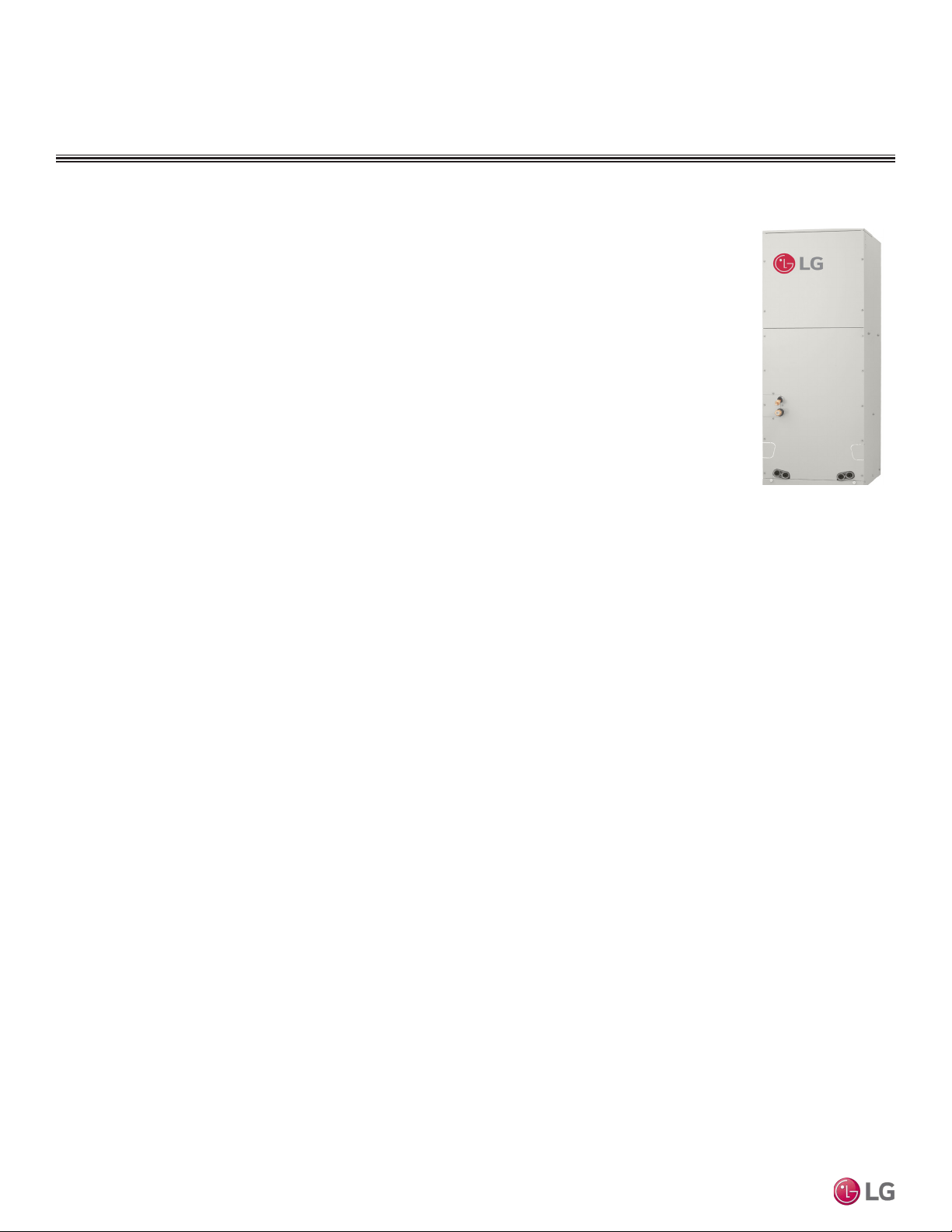
Figure 3: Vertical Air
Handling Indoor Unit.
Loading ...
Loading ...
Loading ...