Loading ...
Loading ...
Loading ...
Due to our policy of continuous product innovation, some specications may change without notication.
©LG Electronics U.S.A., Inc., Englewood Cliffs, NJ. All rights reserved. “LG” is a registered trademark of LG Corp.
40 | PRODUCT DATA
Single Zone Vertical Air Handling Unit Engineering Manual
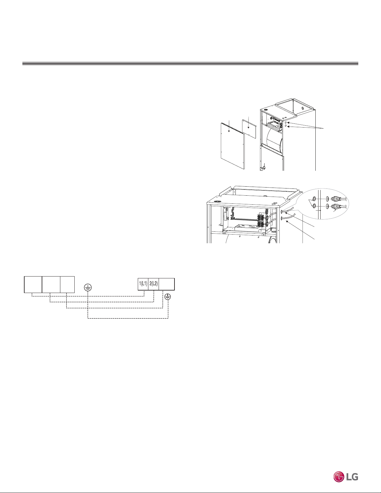
Access Holes
for Wiring
Control
Box Cover
Top Front
Panel
Connection Cable
Communications Cable
Nut
Conduit
Mounting Plate
1/2-inch Conduit
Connecting the Power Wiring and Communications Cable
1. To access the terminal block, first unscrew the top front panel,
and then unscrew the cover from the control box.
2. Knockout the access holes for the wiring. Insert the power wiring/
communications cable from the outdoor unit through the conduits,
pass the conduits through the designated access holes, and
then insert the conduits into the control box. To prevent electro-
magnetic interference and product malfunction, leave a space
between the power wiring and communications cable outside of
the indoor unit.
3. Connect the power wiring and communications cables to the
appropriate terminals on the indoor unit control board. Verify
that the color and terminal numbers from the outdoor unit wiring
match the color and terminal numbers on the indoor unit.
4. Fill in any gaps around the conduit access holes with sealant to
prevent foreign particles from entering the indoor unit.
Figure 27: Connecting the Power Wiring and Communications Cable.
Figure 28: Indoor Unit to Outdoor Unit Power Wiring / Communications Cable
Connections.
ELECTRICAL CONNECTIONS
Indoor Unit Terminal Block
1(L1 )2(L2)
GND
3
Outdoor Unit Terminal Block
GND
GRN /
YLW
BR
BL
RD
3
Loading ...
Loading ...
Loading ...