Loading ...
Loading ...
Loading ...
5 - ENG200-2929
1. Unpack the air compressor. Inspect the unit for damage. If
the unit has been damaged in transit, contact the carrier
and complete a damage claim. Do this immediately
because there are time limitations to damage claims.
The carton should contain:
• aircompressor
• operator/partsmanual
2. Check the compressor’s serial label to ensure that you
have received the model ordered, and that it has the
required pressure rating for its intended use.
3. Locate the compressor according to the following
guidelines:
a. Position the compressor near a grounded electrical
outlet (see GROUNDING INSTRUCTIONS). Avoid
using an extension cord; use a longer air hose instead.
b. The pump side of the compressor must be at least
12 inches (31 cm) from any wall or obstruction, in a
clean, well-ventilated area, to ensure sufficient air
flow and cooling.
c. In cold climates, store portable compressors in a
heated building when not in use. This will reduce
problems with lubrication, motor starting and freezing
of water condensation.
d. The compressor must be level to ensure drainage of the
moisture in the tank.
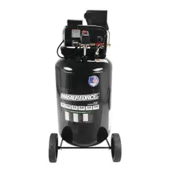
4. Connect an air hose (not included) to the manifold outlet (D).
ASSEMBLY
ASSEMBLING THE COMPRESSOR
Fig. 2
D
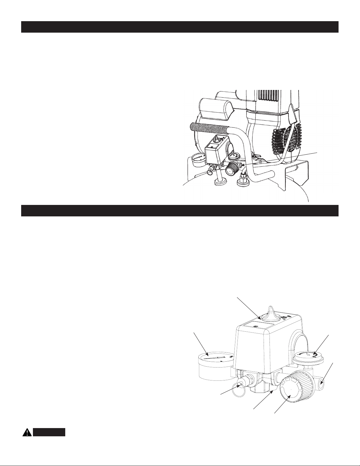
COMPRESSOR CONTROLS
Pressure Switch (see A)
This switch turns on the compressor. It is operated manually,
but when in the AUTO position, it allows the compressor to start
up or shut down automatically, without warning, upon air demand.
ALWAYS set this switch to OFF when the compressor is not
being used, and before unplugging the compressor.
Tank Safety Valve (see B)
Used to allow tank pressure to escape into the atmosphere.
If the pressure switch does not shut off the compressor at it’s “cut-
out” pressure setting, the safety valve will protect against high
pressure by releasing tank pressure at it’s factory set pressure
(slightly higher than the pressure switch “cut-out” setting). To
operate manually, pull the ring on the valve to relieve air pressure
in the tank.
Pressure Release Valve (see C)
The pressure release valve (located on the bottom of the
pressure switch), is designed to release compressed air from the
compressor head and outlet tube when the compressor reaches
“cut-out” or is shut off. The pressure valve allows the motor to
restart freely. When the motor stops running, air will be heard
escaping from this valve for a few seconds. No air should be
heard leaking when the motor is running or after brief release
after reaching “cut-out” pressure.
Tank Pressure Gauge (see D)
This gauge measures the pressure level of the air stored
in the tank. It is not adjustable by the operator, and does not
indicate line pressure.
Air Pressure Regulator (see E)
This air pressure regulator enables you to adjust line
pressure to the tool you are using.
WARNING:
Never exceed the maximum working
pressureofthetool.
To adjust pressure setting, pull out the knob and turn
clockwise to increase pressure, and counterclockwise to
decrease pressure. To lock a pressure setting, push the knob in.
Regulated Pressure Gauge (see F)
This gauge measures the regulated line pressure.
Air line outlet (see G)
Connect 1/4” NPT air hose to this outlet.
Fig. 3
F
E
D
A
B
G
C
Loading ...
Loading ...
Loading ...