Loading ...
Loading ...
Loading ...
AP18733 REV. 3.2.17
43
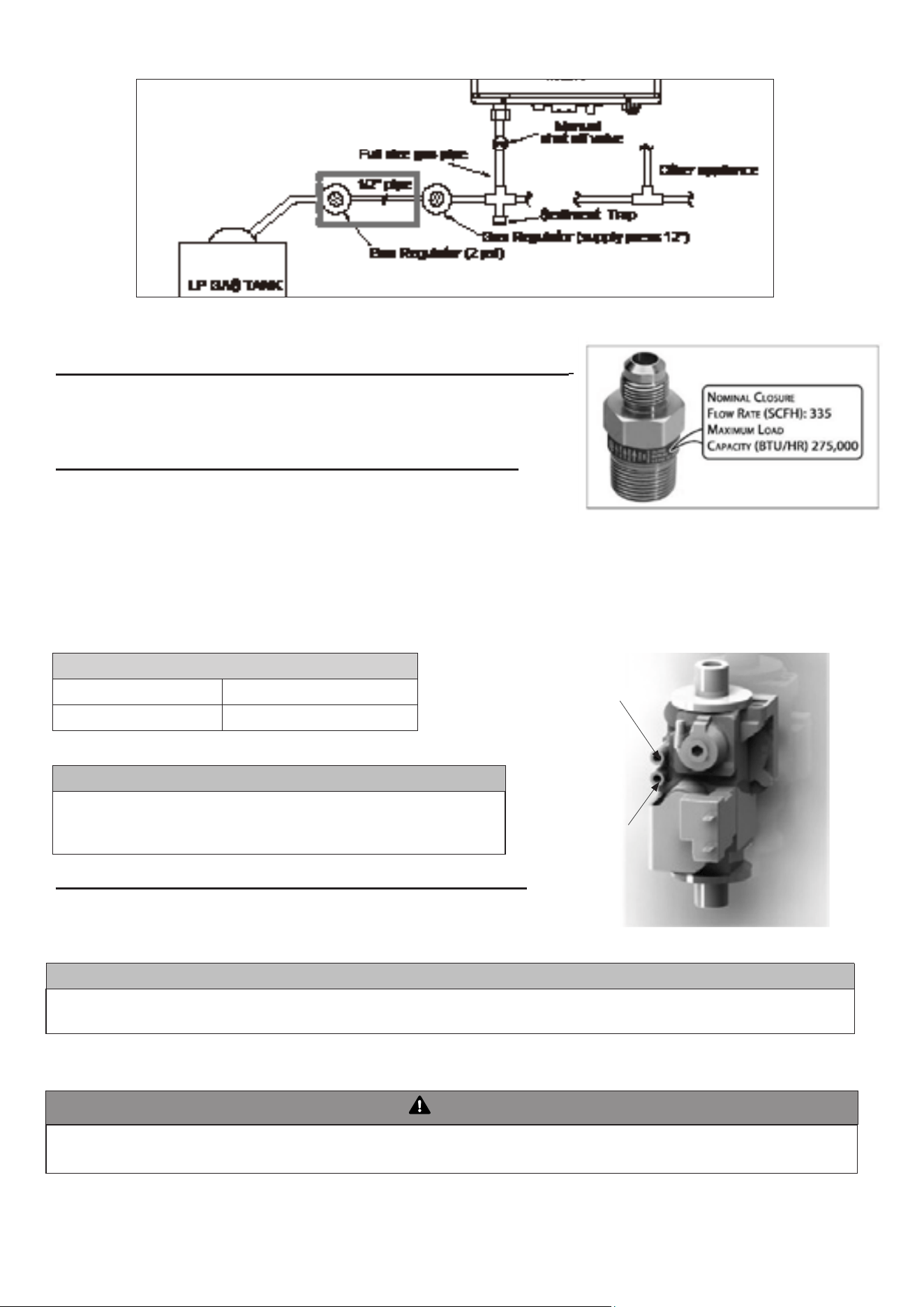
▪ C. ADDITIONAL PRECAUTION FOR EXCESS FLOW VALVE (EFV
)
If an excess ow valve (EFV) is in the gas line, check the manufacturer’s minimum and
maximum ow capacity ratings. An improperly sized EFV will not allow for a full ow of gas
to the water heater and will cause the water heater to malfunction. See Figure 21.
▪ D. ADJUSTING GAS PRESSURE AT THE WATER HEATER
NOTE: Refer Figure 22 when adjusting gas pressure. Loosen the bolts before checking the
gas inlet pressure.
1. The water heater and its individual shutoff valve must be disconnected from the gas
supply piping system during any pressure testing of the system at test pressures greater
than ½ psi (3.5 kPa).
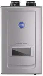
Figure 20 – LP Gas Piping Installation – NOTE: Capacity to be Not Less than Total Capacity of Connected Appliances
2. The water heater must be isolated from the gas supply piping system by closing its individual manual shutoff valve during any pressure testing of
the gas supply piping system at test pressures equal to or less than ½ psi (3.5 kPa). The minimum and maximum inlet gas line pressures must meet
the requirements shown in Table 18.
LP GAS / NATURAL GAS
Minimum Pressure 5.0" W.C (1.25 kPa)
Maximum Pressure 13.0″ W.C (3.24 kPa)
Manifold pressure port
Inlet Gas pressure port
Figure 21 – Excess Flow Valve (EFV)
Table 18 – Gas Pressure Requirements
NOTICE
Do not re (operate) the water heater until all connections have been complet-
ed and the heat exchanger is lled with water. Doing so will damage the water
heater and void the warranty.
Figure 22 – Inlet Gas Pressure Port Detail
▪ E. SETTING AND VERIFYING THE COMBUSTION SETTING
NOTE: Turn on a hot water faucet at a nearby location in the water heating system to
draw water at a high ow rate. This will ensure the water heater will run continuously
while running the combustion test.
NOTICE
Do not re (operate) the water heater until all connections have been completed and the heat exchanger is lled with water. Doing so will
damage the water heater and void the warranty.
1. After the appliance has red, ip DIP switch seven (7) to the ON position (low re). Proceed to check appliance combustion values.
NOTE: Use a combustion analyzer to ensure CO and CO
2
values are within the range shown in Table 19.
WARNING
It is required to use a combustion analyzer to verify nal adjustment according to the combustion chart (Table 19). Failure to do so could
result in serious personal injury or death.
Loading ...
Loading ...
Loading ...