Loading ...
Loading ...
Loading ...
AP18733 REV. 3.2.17
41
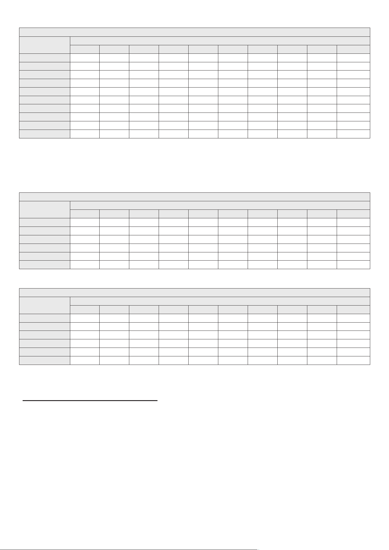
Table 15 – Natural Gas Delivery Capacity – Black Iron Pipe – Refer to ANSI Z223.1 – National Fuel Gas Code, Latest Edition
Table 16 – Liquid Propane Delivery Capacity – Corrugated Stainless Steel Pipe – Refer to ANSI Z223.1 – National Fuel Gas Code, Latest
Edition
Table 17 – Liquid Propane Delivery Capacity – Black Iron Pipe – Refer to ANSI Z223.1 – National Fuel Gas Code, Latest Edition
Maximum Natural Gas Delivery Capacity – Length of Black Iron Pipe (Sch. 40 Metallic) in Feet
Pipe
size
Cubic Feet per Hour (0.60 Specic Gravity, 0.5 WC [0.12 kPa] Pressure Drop)
10 20 30 40 50 60 80 100 150 200
½" (1.2 cm) 10 20 30 40 50 60 80 100 150 200
¾" (1.9 cm) 172 118 95 81 72 65 56 50 40 34
1" (2.5 cm) 360 247 199 170 151 137 117 104 83 71
1 ¼" (3.1 cm) 678 466 374 320 284 257 220 195 157 134
1 ½" (3.8 cm) 1390 957 768 657 583 528 452 400 322 275
2" (5 cm) 2090 1430 1150 985 873 791 677 600 482 412
2 ½" (6.35 cm) 4020 2760 2220 1900 1680 1520 1300 1160 928 794
3" (7.6 cm) 6400 4400 3530 3020 2680 2430 2080 1840 1480 1270
4" (10.1 cm) 11300 7780 6250 5350 4740 4290 3670 3260 2610 2240
23100 15900 12700 10900 9660 8760 7490 6640 5330 4560
Maximum Liquid Propane Delivery Capacity – Length of Corrugated Stainless Steel Pipe in Feet
Pipe
size
Cubic Feet per Hour (1.5 Specic Gravity, 0.5 WC [0.12 kPa] Pressure Drop)
10 20 30 40 50 60 80 100 150 200
½" (1.2 cm) 129 91 74 64 58 53 45 41 31 28
¾" (1.9 cm) 303 216 177 153 137 126 109 98 75 69
1" (2.5 cm) 605 425 344 297 265 241 208 186 143 129
1 ¼" (3.1 cm) 971 661 528 449 397 359 307 270 217 183
1 ½" (3.8 cm) 1990 1400 1140 988 884 805 696 621 506 438
2" (5 cm) 4640 3290 2680 2330 2080 1900 1650 1480 1210 1050
Maximum Liquid Propane Delivery Capacity – Length of Black Iron Pipe (Sch. 40 Metallic) in Feet
Pipe
size
Cubic Feet per Hour (1.5 Specic Gravity, 0.5 WC [0.12 kPa] Pressure Drop)
10 20 30 40 50 60 80 100 150 200
½" (1.2 cm) 291 200 160 137 122 110 101 94 84 67
¾" (1.9 cm) 608 418 336 287 255 231 212 197 175 140
1" (2.5 cm) 1150 787 632 541 480 434 400 372 330 265
1 ¼" (3.1 cm) 2350 1620 1300 1110 985 892 821 763 677 543
1 ½" (3.8 cm) 3520 2420 1940 1660 1480 1340 1230 1140 1010 814
2" (5 cm) 6790 4660 3750 3210 2840 2570 2370 2200 1950 1570
3. LP (Liquid Propane) Gas Pipe Sizing
The following is intended for use for piping between a Single or Second Stage (Low Pressure) Regulator and the water heater. The following
tables list maximum capacity of pipe in cubic feet of gas per hour for an inlet pressure of 14" water column and specic pressure drop of 0.5
inches (0.12 kPa) water column based on 1.5 specic gravity for liquid propane.
1. The gas connection fitting on the water heater is ¾" (1.9 cm) female NPT. NOTE: The pipe size must not be less than ¾" (1.9 cm).
2. The supply line must be sized for the maximum output of the water heater being installed. If there are additional gas appliances from the
main supply line, measure the size of the supply line according to the COMBINED total maximum BTUH draw for the appliances as if they were
operating at the same time.
3. Measure the length of the gas supply line from the gas meter to the water heater. Water heater must be installed downstream of the gas
meter to ensure adequate gas supply. Use the tables in this manual or refer to the gas line manufacturer’s sizing information to determine the
correct supply pipe size.
4. A manual gas shut-off valve should be installed in the gas supply line close to the water heater. See Figure 18 for detail.
5. To facilitate any future maintenance, it is also recommended that an approved gas union fitting be installed in the supply line between the
shut-off valve and the ¾" (1.9 cm) female NPT connection on the water heater.
▪ B. GAS CONNECTION REQUIREMENTS
Loading ...
Loading ...
Loading ...