Loading ...
Loading ...
Loading ...
14
Built-In Installation/Start-Up
Built-In Cabinet Dimensions
Model
Min. Cut-Out Dimensions
Width Height Depth
UR15IM20RS
UL15IM20RS
14-15/16” 34” 24”
Installing a Built-In
Your Electrolux product has been
designed for either free-standing or built-in
installation. When built-in, your ice maker
does not require additional air space for
top, sides or rear. However, the front grille
must NOT be obstructed.
Initial Start-Up
Once installation and leveling is complete,
the unit is ready for initial start-up
and operation. All units are shipped
with controls that are preset. No initial
adjustments are required.
Plug into a 115 volt polarized and
grounded electrical outlet.
Open the water supply valve at the main
water source.
IMPORTANT
It is possible that dirt or scale will
dislodge in the water line. Always throw
away all ice cubes made during the first
two to three hours of operation.
CAUTION
DO NOT install unit behind closed doors.
NOTE
To ease unit installation and removal,
the unit must be located to allow
clearance for water, drain and electrical
connections in the rear of the ice maker.
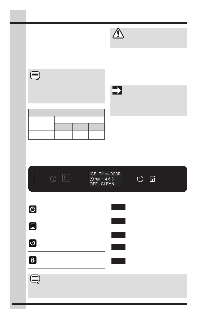
USING YOUR ELECTRONIC CONTROL
Display icons:
"lock" icon: used to lock out
functions in the user interface.
"menu" icon: used to access optional
functions in the user interface.
"on-off" icon: used for turning the
appliance on and off and confirming
selections.
"timer" icon: used to enter the Delay
start/vacation mode.
Display area text:
Signifies the appliance is off
OFF
Signifies the appliance is on and
producing ice.
ICE
Signifies the appliance is in
economical ice production mode.
ECO
Signifies a door ajar alarm
condition.
DOOR
Cleaning is recommended or the
appliance is in the clean mode.
CLEAN
NOTE
The control display is covered with a clear plastic film. This film may be removed by
carefully lifting at a corner.
timer
lock
on-off menu
Loading ...
Loading ...
Loading ...