Quick Installation Guide
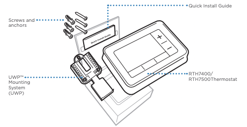
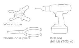
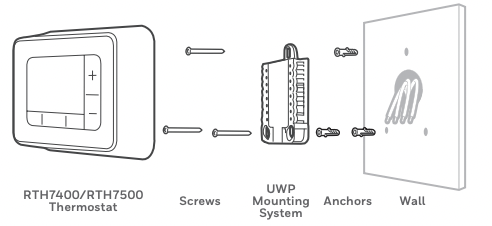
Included in your box
Removing your old thermostat
1. Turn power OFF
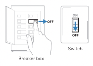
 To protect yourself and your equipment, Turn off the power at the breaker box or switch that controls your heating/cooling system.
2 Check that your system is off.
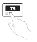
Change the temperature on your old thermostat. If you don’t hear the system turn on within 5 minutes, the power is off.
Note: If you have a digital thermostat that has a blank display, skip this step
3 Remove the old thermostat’s faceplate.
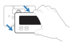
On most thermostats, you can take off the faceplate by grasping and gently pulling. Some thermostats may have screws, buttons, or clasps.
Do not remove any wires from your thermostat at this time!
4 Make sure there are no 120/240V wires.
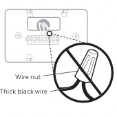
Do you have thick black wires with wire nuts? Is your thermostat 120V or higher?
If you answered yes to either of these questions, you have a line voltage system and the thermostat will not work.
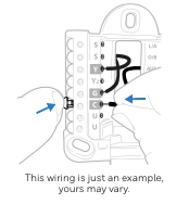
5 Take a picture of how your wiring looks right now.
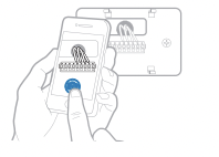
Be sure to include the letters next to the terminals where the wires are inserted. This will be a helpful reference when wiring your thermostat.
Tip: If the color of your wires has faded or if 2 terminals have the same wire color, use the wire labels provided in the package to label each wire.
6. Remove any jumpers
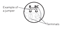
A jumper connects one terminal to another terminal. It may look like a small staple or even a colored wire and must be removed before continuing. Use a screwdriver to release wires from terminals.
The RTH7400/RTH7500 thermostat does not need jumpers.
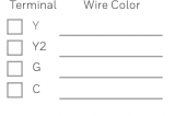
7 Record if you have wires in the following terminals.
Do not include jumpers as a part of your count. The thermostat does not need jumpers.
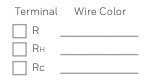
8 Write down the color of the wires.
Check mark the wires that are connected to terminals. Next to the check mark, write down the color of the wire.
Do not include jumpers as a part of your count. Check all that apply (Not all will apply):
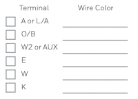
The RTH7400/RTH7500 thermostat does not support L/A, S, or U terminals. If there are wires in terminals that are not listed, you will need additional wiring support.
9 Disconnect the wires and remove the old wall plate.
Use a screwdriver to release wires from terminals. Then, use a wire label to identify each wire as it’s disconnected. The letter on the wire label should match the letter on the terminal.
Tip: To prevent wires from falling back into the wall, wrap the wires around a pencil.
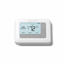
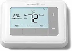
Installing your RTH7400/RTH7500 thermostat
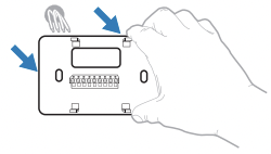
10 Bundle and insert wires through the UWP.
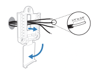
Pull open the UWP and insert the bundle of wires through the back of the UWP. Make sure at least 1/4-inch of each wire is exposed for easy insertion into the wire terminals.
11 Insert the wall anchors.
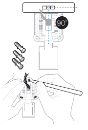
It is recommended that you use the wall anchors included in the box to mount your thermostat. You can use the UWP to mark where you want to place the wall anchors.
a) Level the wall plate.
b) Mark the location of the wall anchors using a pencil.
c) Drill the holes.
d) Insert wall anchors.
e) Make sure anchors are flush with wall.
Tip: Use a 7/32 drill bit
12 Set R-switch position and insert R-wire or wires.
Set the R-switch up or down based on your wiring notes in Step 7
Insert wires into the inner holes of the terminals on the UWP. The tabs will stay down once the wire is inserted.
If you have 1 R-wire (R,Rh, or Rc)
 1. Set R-switch to the up position.
 2. Insert your R-wire (R, Rh or Rc) into R-terminal.
or If you have 2 R-wires (R or Rh, and Rc)
 1. Set R-switch to the down position.
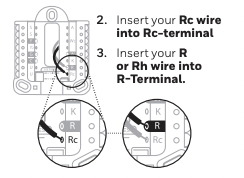
2. Insert your Rc wire into Rc-terminal
3. Insert your R or Rh wire into R-Terminal.
13 Connect wires from Step 8.
Depress the tabs to put the wires into the inner holes of their corresponding terminals on the UWP (one wire per terminal) until it is firmly in place.
Gently tug on the wires to verify they are secure.
Tip: If you need to release the wires again, push down the terminal tabs on the sides of the UWP.
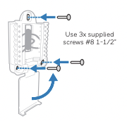
14 Mount the UWP and close the door.
Mount the UWP using the provided screws. Install all three screws for a secure fit on your wall. Close the door after you’re finished.
15 Confirm wiring matches snapshot.
Please confirm wiring matches terminals from the photo you took in Step 5.
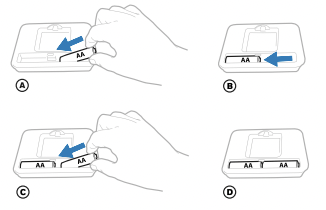
16 Install batteries.
Insert two AA alkaline batteries in the back of the thermostat as shown.
17 Attach your thermostat.
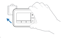
Align the thermostat onto the UWP and firmly snap it into place.
18 Turn your power ON.
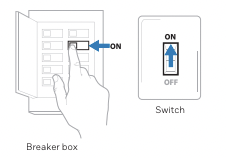
Turn on the power at the breaker box or switch that controls the heating/ cooling system.
Set date and time
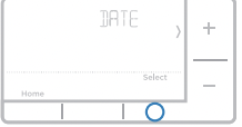
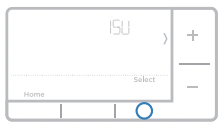
19 Set the date.
- Press + or - to adjust the year. Press Select.
- Press + or - to adjust the month. Press Select.
- Press + or - to adjust the day. Press Select.
20 Choose a clock format.
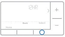
Press + or - set the clock format: 12 hour (standard for North America) or 24 hour. Press Select.
21 Set the time.
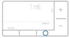
- Press + or - to adjust the hour. Press Select.
- Press + or - to adjust the minutes. Press Select.
System Setup
NOTE: If this is not a new installation, see page 14 for entering setup menu.
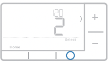
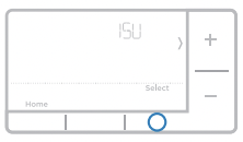
22 Select System Setup options.
Press + or - to change values or select from available options. Then press Select to save changes and advance to the next System Setup number.
See “System Setup options” below for a full list of System Setup numbers and options.
Repeat until all of the System Setup options have been set. The thermostat will automatically save and exit to the Home screen.
23 Continue to “System operation settings” on page 10.
System Setup options
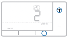
120 Scheduling Options
- 0 = Non-Programmable
- 1 = 1-Week Programmable
- 2 = 5-2 Programmable
- 3 = 5-1-1 Programmable (RTH7460 only)
- 4 = 7-Day Programmable (RTH7560 only)
Note: You can change default MO-FR, SA-SU schedule here. To edit periods during days, temperature setpoints, or to turn Schedule On/Off, touch MENU and go to SCHEDULE.
125 Temperature Indication Scale
- 0 = Fahrenheit
- 1 = Celsius
200 Heating System Type
- 1 = Conventional Forced Air Heat
- 2 = Heat Pump
- 3 = Radiant Heat (Boiler)
- 5 = None (Cool Only)
Note: This option selects the basic system type your thermostat will control.
205 Heating Equipment Type
Conventional Forced Air Heat:
- 1 = Standard Efficiency Gas Forced Air
- 2 = High Efficiency Gas Forced Air
- 3 = Oil Forced Air
- 4 = Electric Forced Air
- 5 = Hot Water Fan Coil
Heat Pump:
Radiant Heat:
- 9 = Hot Water Radiant Heat
- 12 = Steam
Note: This option selects the equipment type your thermostat will control. Note: This feature is NOT displayed if feature 200 is set to Cool Only.
218 Reversing Valve O/B
- 0 = O (O/B in Cool)
- 1 = B (O/B in Heat)
Note: This option is only displayed if the Heat Pump configured. Select whether reversing valve O/B should energize in cool or in heat.
220 Cool Stages / Compressor Stages 200=Conv / 200=HP
Note: Select how many Cool or Compressor stages of your equipment the thermostat will control. Maximum of 2 Cool/Compressor Stages. Set value to 0 if you do not have Cool Stage/Compressor Stage.
221 Heat Stages / Backup Heat Stages Heat Stages
- Heat Stages: 1, 2
- Backup Heat Stages: 0, 1
Note: Select how many Heat or Aux/E stages of your equipment the thermostat will control. Maximum of 2 Heat Stages for conventional systems. Maximum of 1 Aux/E stage for systems with more than 1 heating equipment type. Set value to 0 if you do not have Heat Stage/ Backup Heat Stage.
300 System Changeover
Note: Thermostat can automatically control both heating and cooling to maintain the desired indoor temperature. To be able to select “automatic” system mode on thermostat home screen, turn this feature ON. Turn OFF if you want to control heating or cooling manually.
425 Smart Response
- 0 = No
- 1 = Yes
- Note: Smart Response is a comfort setting. Heat or Cooling equipment will turn on earlier, ensuring the indoor temperature will match the setpoint at the scheduled time. See page 15.
430 Minimum Cool Temperature Setpoint (RTH7500 Only)
- 50 °F to 99 °F (50 °F)
- 10.0 °C to 37.0 °C (10.0 °C)
Note: The cool temperature cannot be set below this level.
431 Maximum Heat Temperature Setpoint (RTH7500 Only)
- 40 °F to 90 °F (90 °F)
- 4.5 °C to 32.0 °C (32.0 °C)
Note: The heat temperature cannot be set above this level.
711 Air Filter 1 Replacement Reminder
- 0 = Off
- 1 = 10 Run Time Days
- 2 = 20 Run Time Days
- 3 = 30 Run Time Days
- 4 = 45 Run Time Days
- 5 = 60 Run Time Days
- 6 = 90 Run Time Days
- 7 = 120 Run Time Days
- 8 = 150 Run Time Days
- 9 = 30 Calendar Days
- 10 = 45 Calendar Days
- 11 = 60 Calendar Days
- 12 = 75 Calendar Days
- 13 = 3 Calendar Months
- 14 = 4 Calendar Months
- 15 = 5 Calendar Months
- 16 = 6 Calendar Months
- 17 = 9 Calendar Months
- 18 = 12 Calendar Months
- 19 = 15 Calendar Months
Note: Set a reminder for when to change your air filter. Choose either calendar or equipment run time-based reminder.
1415 Daylight saving time
Note: Set to Off in areas that do not follow Daylight Saving Time.
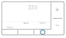
NOTE: Once you have cycled through all of the System Setup numbers, Done is displayed. Press Select to save and exit.
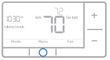
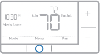
System operation settings
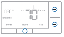
1 Press the Mode button to cycle to the next available System mode.
2 Cycle through the modes until the required System mode is displayed and leave it to activate.
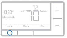
NOTE: Available System modes vary by model and system settings.
System modes:
‒ Auto: Thermostat selects heating or cooling as needed.
‒ Heat: Thermostat controls only the heating system.
‒ Cool: Thermostat controls only the cooling system.
‒ Em Heat (only for heat pumps with auxiliary heat): Thermostat controls Auxiliary Heat. Compressor is not used.
‒ Off: Heating and cooling system is off. Fan will still operate if fan is set to On or Circulate.
NOTE: Heat/Cool flash for 5 minutes due to compressor protection.
Fan operation settings
1 Press the Fan button to cycle to the next available Fan mode.
2 Cycle through the modes until the required Fan mode is displayed and leave it to activate.
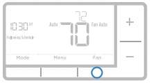
NOTE: Available Fan modes vary with system settings.
Fan modes:
‒ Auto: Fan runs only when the heating or cooling system is on.
‒ On: Fan is always on.
‒ Circ (RTH7500 Only): Fan circulates randomly about 33% of the time.
Program Schedule
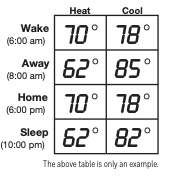
You can program four time periods each day, with different settings for weekdays and weekends. We recommend the pre-set settings (shown in the table below), since they can reduce your heating/cooling expenses.
- Wake - Set to the time you wake up and the temperature you want during the morning, until you leave for the day.
- Away - Set to the time you leave home and the temperature you want while you are away (usually an energy-saving level).
- Home - Set to the time you return home and the temperature you want during the evening, until bedtime.
- Sleep - Set to the time you go to bed and the temperature you want overnight (usually an energysaving level).
NOTE: To temporarily or permanently override any of the above program schedules, see page 12.
To adjust program schedules
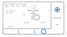
- 1 Press Menu on your thermostat.
- 2 PROG is displayed. Press Select. Then ON is displayed. Press Select.
- 3 Press + or - to select day or set of days to edit. Press Select.
- 4 Press + or - to select a schedule period to edit (Wake, Away, Home, and Sleep). Press Select.
- 5 ON is displayed. Press Select to keep the schedule period on. Or press + and then Select to turn off the schedule period.
- 6 Time starts blinking. Press + or - to adjust the schedule period start time. Press Select.
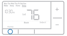
- 7 Temperature starts blinking. Press + or - to adjust the “Heat” setpoint temperature. Press Select. Press + or - to adjust the “Cool” temperature setpoint. Press Select.
- 8 Repeat steps 4 through 7 for the remaining schedule periods.
- 9 Press Home when you’re finished to save program settings and return to the home screen.
Program schedule override (temporary)
- 1 Press + or - to adjust the temperature.
- 2 Once at the desired setpoint temperature, no further action is needed. The new setpoint temperature will be held until the next scheduled time period begins. For more information on schedule time periods, see “Program Schedule” on page 11.
- 3 To cancel the Temporary Hold, Press + or - and then press Cancel.
Program schedule override (permanent)
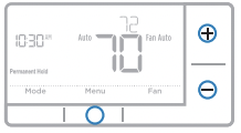
1 Press + or - to adjust the temperature.
2 TEMPORARY HOLD is displayed and the setpoint temperature flashes. While it’s flashing, press Hold (Mode) button to change to Permanent Hold.
3 To cancel the Permanent Hold, press + or - and then press Cancel.
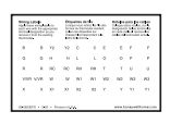
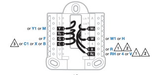
Wiring—conventional systems
Alternate wiring (conventional systems)
If labels do not match terminals, connect wires as shown below (see notes, below).
NOTES:
1. If you must connect both R and Rc wires, set the R Slider Tab to the down position (2 wires).
2. If your old thermostat had both R and RH wires, set the R Slider Tab to the down position (2 wires). Then connect the R wire to the Rc terminal, and the RH wire to the R terminal.
3. If your old thermostat had only 1 C or C1 wire, connect it to the C terminal. If your old thermostat had 2 C or C1 wires, wrap each separately with electrical tape and do not connect them.
Wiring—heat pump
Connect wires: heat pump
1 Match each labeled wire with same letter on new thermostat.
2 Insert the wires into the matching terminal.
NOTE: If you have difficulty inserting wires, you may have to press down the terminal push button next to the corresponding terminal. Labels don’t match? If labels do not match letters on thermostat, see page 13.
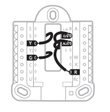
Alternate wiring (for heat pumps only)
NOTES:
- 1. Keep R Slider Tab in the up position (1 wire).
- 2. If your old thermostat had both V and VR wires, stop now and contact a qualified contractor for help.
- 3. If your old thermostat had separate O and B wires, attach the B wire to the C terminal. If another wire is attached to the C terminal, stop now and contact a qualified contractor for help.
- 4. If your old thermostat had Y1, W1 and W2 wires, stop now and contact a qualified contractor for help.
- 5. C does not power the thermostat display or operations; batteries are always required.
- 6. This model doesn’t support the heat pump fault alert (L/A terminal). If this is desired, please contact a contractor for replacement model.
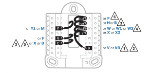
NOTE: Do NOT use W for heat pump applications. Auxiliary heat must wire to AUX or E.
1 Press and hold Menu and + buttons for approximately 5 seconds to enter advanced menu.

2 Press Select to enter System Setup (ISU) menu.
3 Press Select to cycle through System Setup numbers.
NOTE: See “System Setup options” on page 8 for a full list of System Setup numbers and options
4 Press + or - to change values or select from available options.
5 Press Select to save changes and advance to the next System Setup number.
6 Once you have cycled through all of the System Setup numbers, “Done” is displayed. Press Select to save and exit. To save and exit early, press Home to return to the Home screen.
Smart Response® Technology
This feature allows the thermostat to “learn” how long the furnace and air conditioner take to reach programmed temperature settings, so the temperature is reached at the time you set. For example: Set the Wake time to 6 am, and the temperature to 70°. The heat will come on before 6 am, so the temperature is 70° by the time you wake at 6. The message “Recovery” is displayed when the system is activated before a scheduled time period.
Battery replacement

Batteries are required to provide power. Install fresh batteries immediately when the low battery icon appears. The icon appears about two months before the batteries are depleted.
Even if the low battery icon does not appear, you should replace batteries once a year, or before leaving home for more than a month.
If batteries are inserted within two minutes, the time and day will not have to be reset. All other settings are permanently stored in memory, and do not require battery power.
NOTE: When replacing batteries, alkaline batteries are recommended.
Setting the time
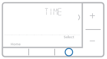
- 1 Press Menu to enter the device menu. You will see PROG. Press + or - to choose TIME.
- 2 Press Select.
- 3 12HR is displayed. Press + or - to choose a 12 hour clock or a 24 hour clock. Press Select.
- 4 Set the time. Press + or - to adjust the hour. Press Select.
- 5 Press + or - to adjust the minutes. Press Select. Press Select to save and exit.
Set the date
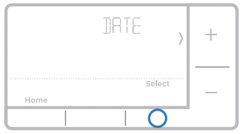
- 1 Press Menu to enter the device menu. You will see PROG. Press + or - to choose DATE.
- 2 Press Select.
- 3 You will see the year blinking. Press + or - to adjust the year. Press Select.
- 4 Press + or - to adjust the month. Press Select.
- 5 Press + or - to adjust the day. Press Select to save and exit.
Setting degrees Fahrenheit (F) or Celsius (C)
- 1 Press Menu to enter the device menu. You will see PROG. Press + or - to choose F/C.
- 2 Press Select.
- 3 You will see F or C displayed.
- 4 Press + or - to adjust to the desired setting. F for Fahrenheit and C for Celsius. Press Select to save and exit.
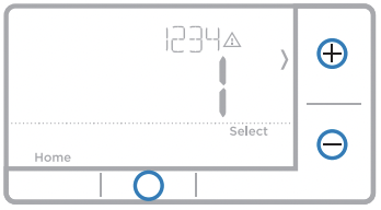
Alerts screen
- 1 You will see the alert icon
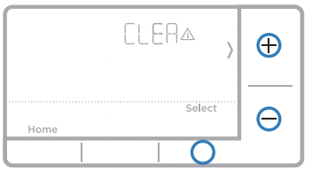
 on the home screen. You can access alerts in the Menu to view the error/alert code. Once viewed the home screen will maintain the alert symbol until it is cleared.
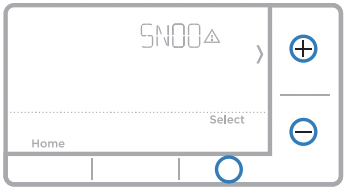
- 2 Snoozed alerts will appear 7 days after dismissing them in the alerts menu screen.
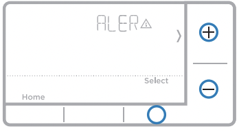
- 3 When the alert icon appears, check the error code with the table below to determine the problem.
Alerts codes
Number 170
Alert/Reminder Internal Memory Error
Definition The memory of the thermostat has encountered an error. Please replace the thermostat.
Number 173
Alert/Reminder Thermostat Temperature Sensor Error
Definition The sensor of the thermostat has encountered an error. Please replace the thermostat.
Number 181
Alert/Reminder Replace Air Filter (1)
Definition Replace air filter (1). Reset the timer by touching the "dismiss" button on thermostat screen after it is replaced.
Number 405
Alert/Reminder Low Battery Alert
Definition The batteries are getting low. Replace them within two months.
Number 407
Alert/Reminder Critical Low Battery
Definition The batteries are almost depleted and should be replaced as soon as possible.
Troubleshooting
If you have difficulty with your thermostat, please try the following suggestions. Most problems can be corrected quickly and easily.
Display is blank
- Make sure fresh AA alkaline batteries are properly installed (see page 6).
Cannot change system setting to Cool
- Check System Setup Option 220 to make sure the options are set to either 1 or 2 (see page 9).
Fan does not turn on when heat is required
- Check System Setup Option 205 to make sure it is set to match your heating equipment (see page 8).
Heating system is running in cool mode
- Check System Setup Option 200 or 218 to make sure it is set to match your heating and cooling equipment (see page 9).
Heating or cooling system does not respond
- Press System to set system to Heat. Make sure the temperature is set higher than the Inside temperature.
- Press System to set system to Cool. Make sure the temperature is set lower than the Inside temperature.
- Check circuit breaker and reset if necessary.
- Make sure power switch at heating & cooling system is on.
- Make sure furnace door is closed securely.
- Wait 5 minutes for the system to respond.
Heat On / Cool On flashing on the screen
- Compressor protection feature is engaged. Wait 5 minutes for the system to restart safely, without damage to the compressor.
Heat pump issues cool air in heat mode, or warm air in cool mode
- Check System Setup Option 200 or 218 to make sure it is set to match your heating and cooling equipment (see page 8).
Electrical Ratings
Terminal Voltage (50/60Hz) Running Current
W Heating 20-30 Vac 0.02-1.0 A
W2 (Aux) Heating 20-30 Vac 0.02-1.0 A
E Emergency Heat 20-30 Vac 0.02-0.5 A
Y Compressor Stage 1 20-30 Vac 0.02-1.0 A
Y2 Compressor Stage 2 20-30 Vac 0.02-1.0 A
G Fan 20-30 Vac 0.02-0.5 A
O/B Changeover 20-30 Vac 0.02-0.5 A
L/A Input Unused Unused
NOTE: Not for use with 250, 500, or 750 MV systems.