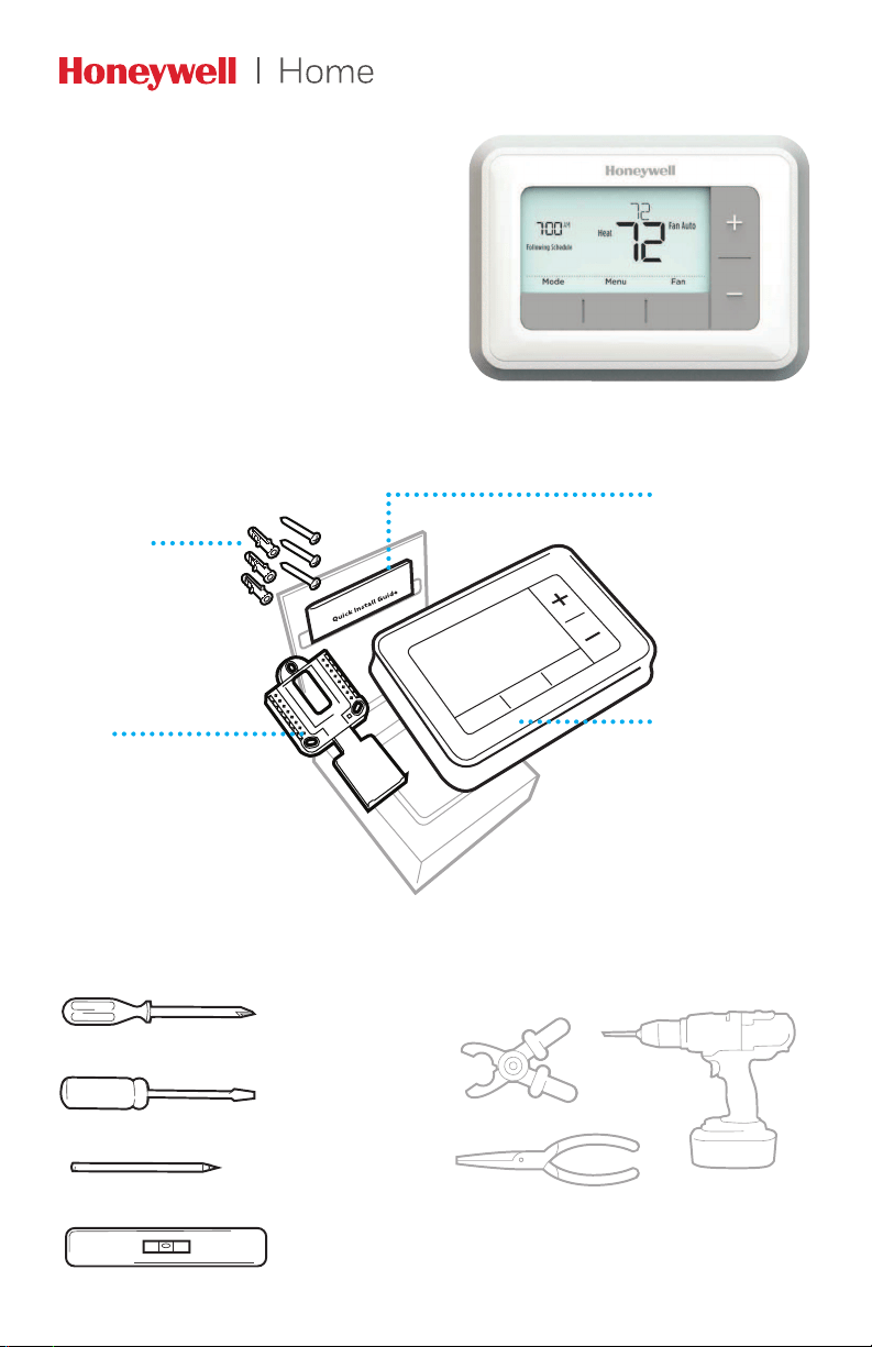
RTH7500 Series
Programmable Thermostat
Quick Installation Guide
Tools you will need Tools you may need
Wire stripper
Needle-nose pliers Drill and
drill bit (7/32 in)
Included in your box
Screws and
anchors
UWP
Mounting
System
(UWP)
RTH7500
Thermostat
Quick Install Guide
Small flat head scr
ewdriver
Phillips scr
ewdriver
Pencil
Level

2
Quick Installation Guide
Removing your old thermostat
2 Check that your system is off.
Change the temperature on your
old thermostat. If you don’t hear the
system turn on within 5 minutes, the
power is off.
Note: If you have a digital
thermostat that has a blank display,
skip this step.
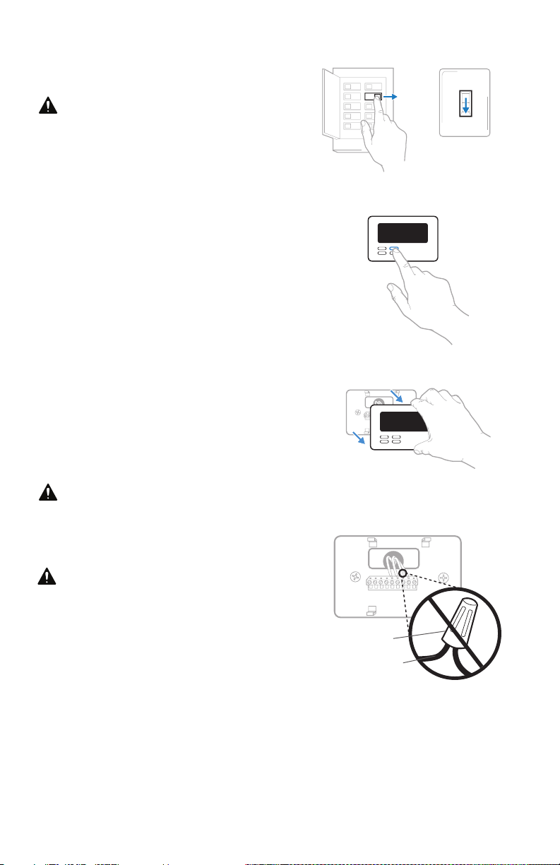
1 Turn power OFF.
To protect yourself and your
equipment, Turn off the power at the
breaker box or switch that controls
your heating/cooling system.
3 Remove the old thermostat’s
faceplate.
On most thermostats, you can take
off the faceplate by grasping and
gently pulling. Some thermostats
may have screws, buttons, or clasps.
Do not remove any wires from your
thermostat at this time!
75
OFF
OFF
ON
Breaker box
Switch
4 Make sure there are no 120/240V
wires.
Do you have thick black wires with
wire nuts?
Is your thermostat 120V or higher?
If you answered yes to either of
these questions, you have a line
voltage system and the thermostat
will not work.
If you are unsure visit:
yourhome.honeywell.com/support
Wire nut
Thick black wire
3
RTH7500 Series
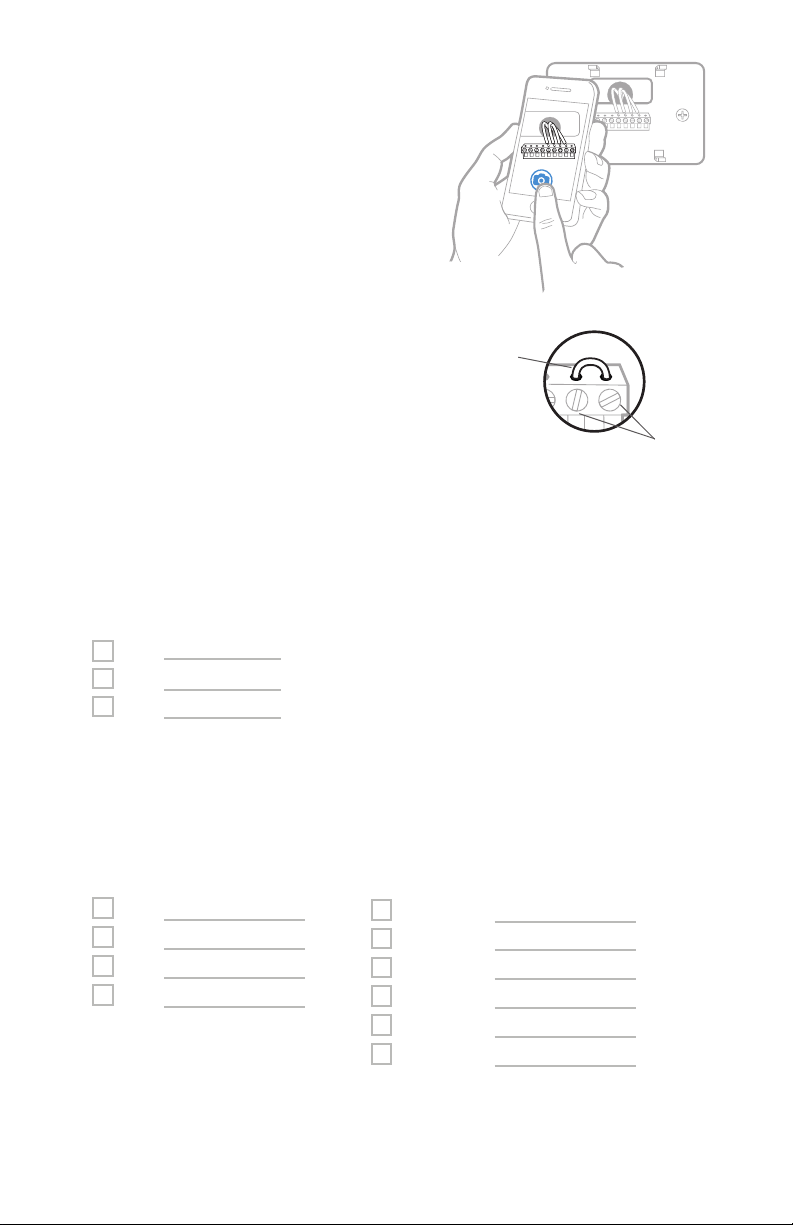
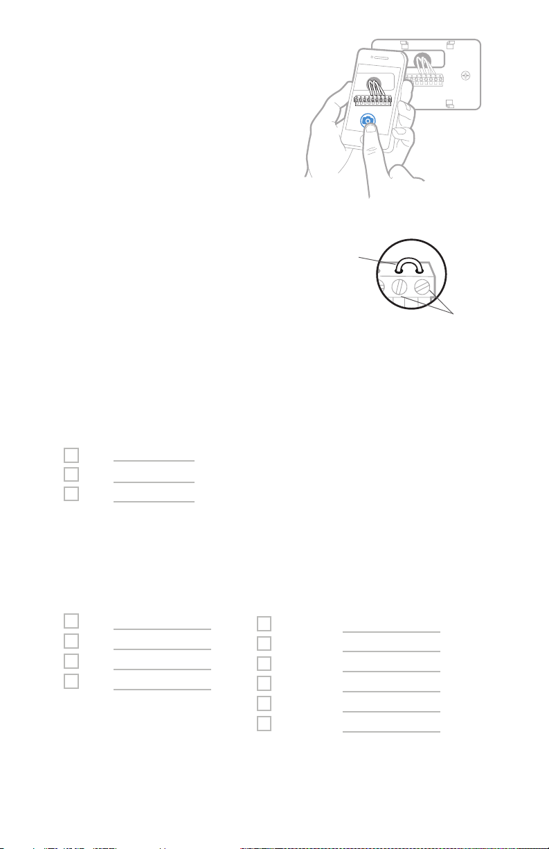
5 Take a picture of how your wiring
looks right now.
Be sure to include the letters
next to the terminals where the
wires are inserted. This will be a
helpful reference when wiring your
thermostat.
Tip: If the color of your wires has
faded or if 2 terminals have the
same wire color, use the wire labels
provided in the package to label
each wire.
6 Remove any jumpers.
A jumper connects one terminal to
another terminal. It may look like
a small staple or even a colored
wire and must be removed before
continuing. Use a screwdriver to
release wires from terminals.
The RTH7500 thermostat does not
need jumpers.
Y
R RC
Example of
a jumper
Terminals
7 Record if you have wires in the following terminals.
Do not include jumpers as a part of your count. The thermostat does not
need jumpers.
Terminal Wire Color
R
R
H
Rc
8 Write down the color of the wires.
Check mark the wires that are connected to terminals. Next to the check mark,
write down the color of the wire. Do not include jumpers as a part of your
count.
Check all that apply (Not all will apply):
Terminal Wire Color
Y
Y2
G
C
Terminal Wire Color
A or L/A
O/B
W2 or AUX
E
W
K
The RTH7500 thermostat does not support L/A, S, or U terminals.
If there are wires in terminals that are not listed, you will need additional
wiring support. Visit yourhome.honeywell.com/support to find out if the
thermostat will work for you.
4
Quick Installation Guide
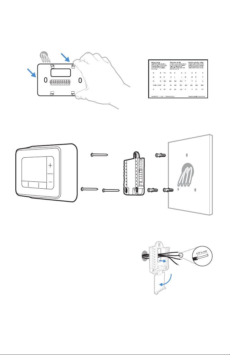
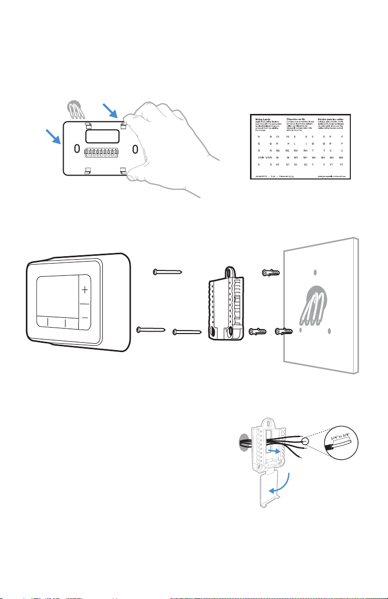
9 Disconnect the wires and remove the old wall plate.
Use a screwdriver to release wires from terminals. Then, use a wire label to
identify each wire as it’s disconnected. The letter on the wire label should
match the letter on the terminal.
Tip: To prevent wires from falling back into the wall, wrap the wires around a
pencil.
Installing your RTH7500 thermostat
10 Bundle and insert wires through the UWP.
Pull open the UWP and insert the bundle of
wires through the back of the UWP.
Make sure at least 1/4-inch of each wire
is exposed for easy insertion into the wire
terminals.
RTH7500
Thermostat
Screws
UWP
Mounting
System
Anchors Wall
5
RTH7500 Series
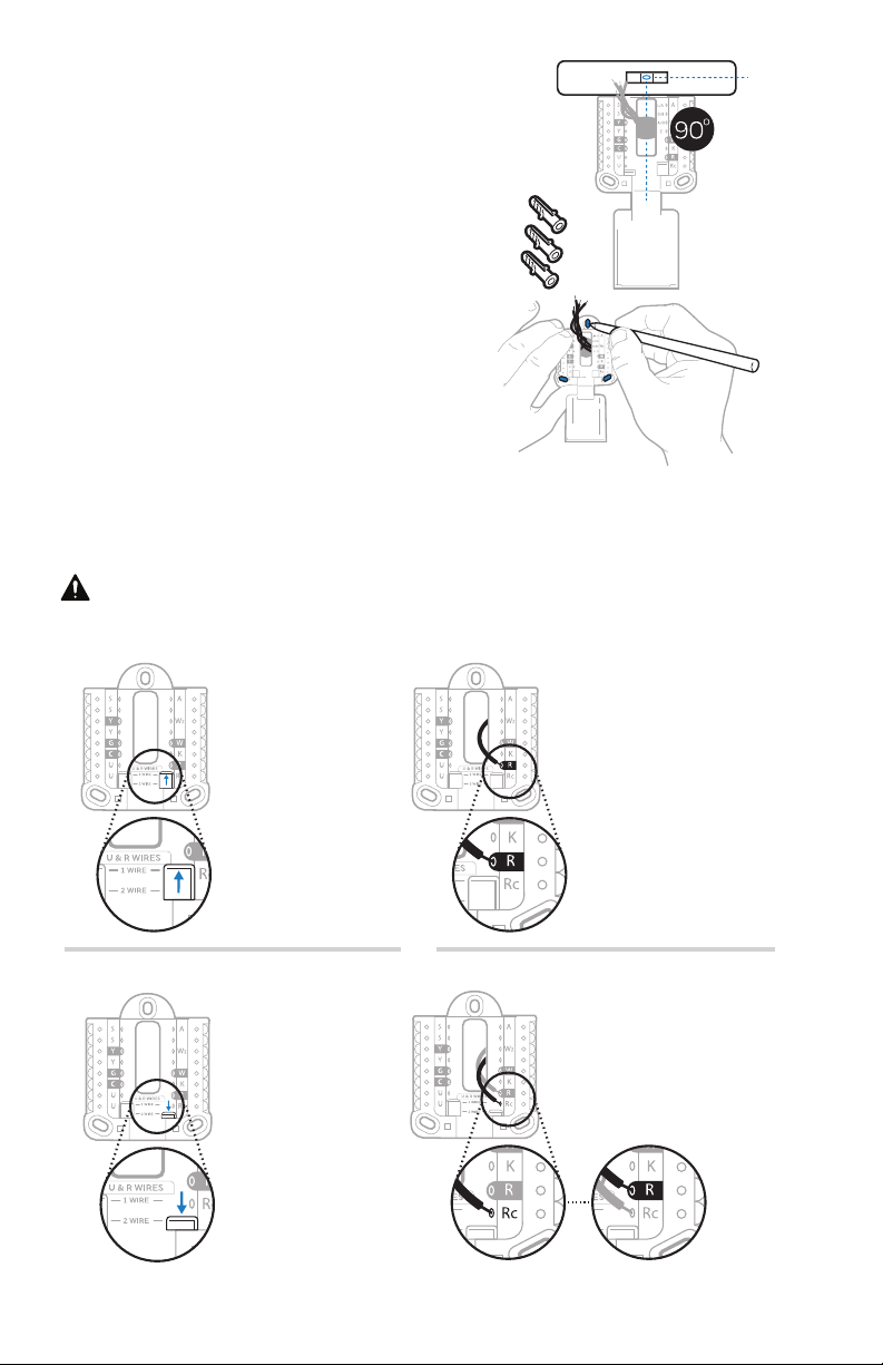
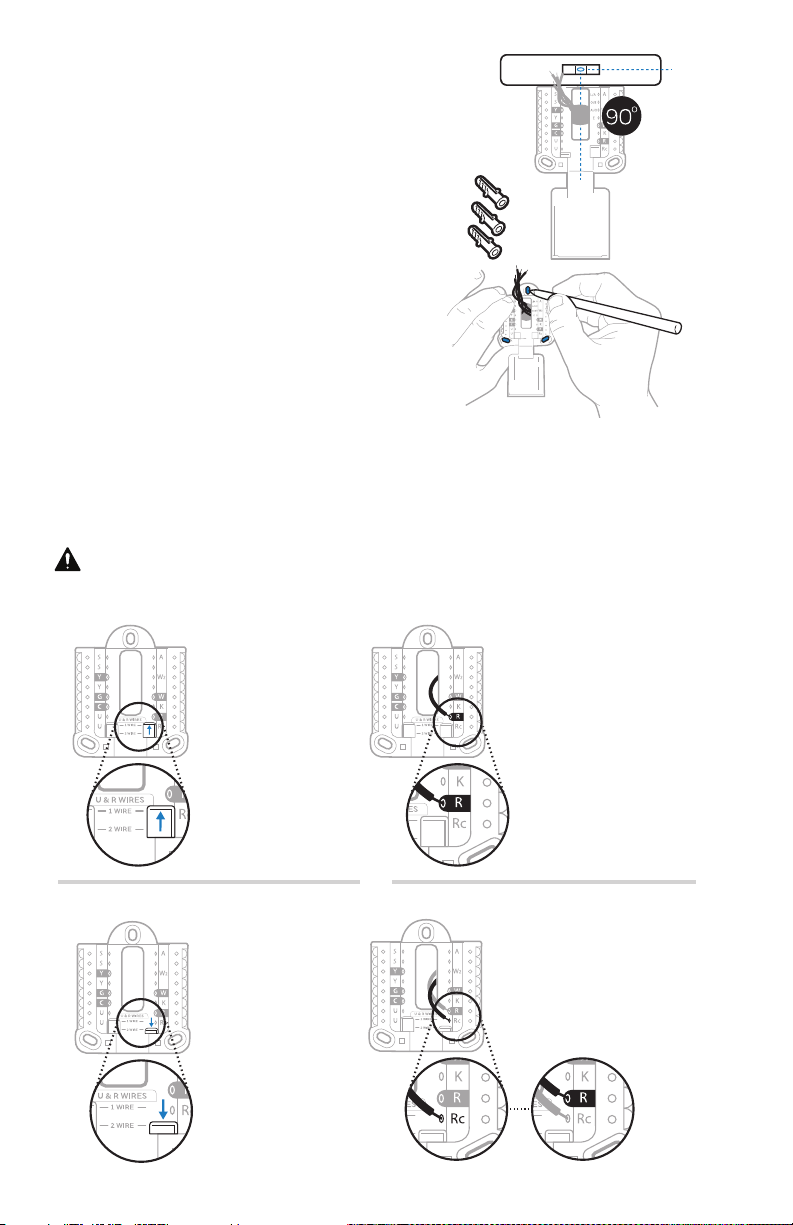
11 Insert the wall anchors.
It is recommended that you use the
wall anchors included in the box to
mount your thermostat.
You can use the UWP to mark where
you want to place the wall anchors.
a) Level the wall plate.
b) Mark the location of the wall
anchors using a pencil.
c) Drill the holes.
d) Insert wall anchors.
e) Make sure anchors are flush with
wall.
Tip: Use a 7/32 drill bit.
Insert wires into the inner holes of the terminals on the UWP. The tabs will
stay down once the wire is inserted.
If you have 1 R-wire (R,Rh, or Rc)
If you have 2 R-wires (R or Rh, and Rc)
or
1. Set R-switch
to the up
position.
1. Set R-switch
to the down
position.
2. Insert your
R-wire (R, Rh
or Rc) into
R-terminal.
2. Insert your Rc wire
into Rc-terminal.
3. Insert your R
or Rh wire into
RTerminal.
12 Set R-switch position and insert R-wire or wires.
Set the R-switch up or down based on your wiring notes in Step 7.
6
Quick Installation Guide
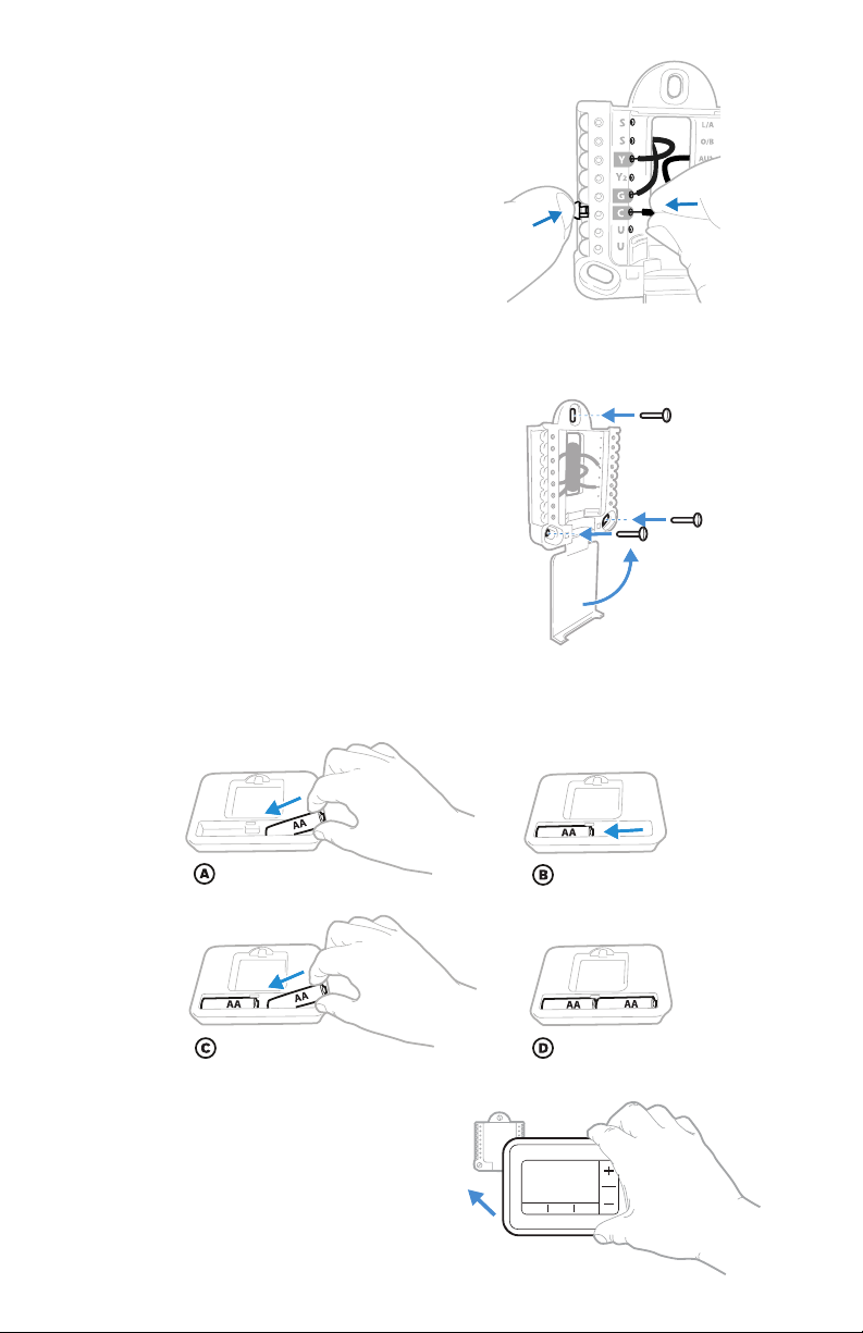
14 Mount the UWP and close the
door.
Mount the UWP using the provided
screws. Install all three screws for
a secure fit on your wall. Close the
door after you’re finished.
15 Confirm wiring matches snapshot.
Please confirm wiring matches
terminals from the photo you took in
Step 5.
Use 3x supplied
screws #8 11/2”
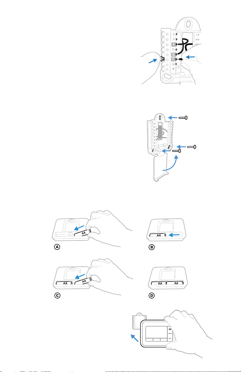
16 Install batteries.
Insert two AA alkaline batteries in the back of the thermostat as shown.
17 Attach your thermostat.
Align the thermostat onto the UWP
and firmly snap it into place.
13 Connect wires from Step 8.
Depress the tabs to put the
wires into the inner holes of their
corresponding terminals on the
UWP (one wire per terminal) until it is
firmly in place.
Gently tug on the wires to verify
they are secure.
Tip: If you need to release the wires
again, push down the terminal tabs
on the sides of the UWP.
This wiring is just an example,
yours may vary.
7
RTH7500 Series
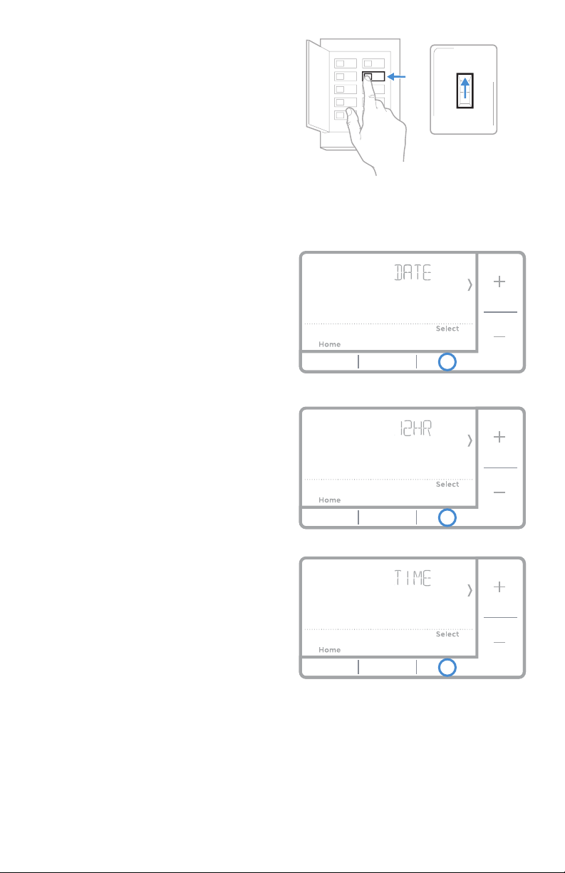
18 Turn your power ON.
Turn on the power at the breaker box
or switch that controls the heating/
cooling system.
19 Set the date.
Press + or - to adjust the year. Press
Select.
Press + or - to adjust the month.
Press Select.
Press + or - to adjust the day. Press
Select.
20 Choose a clock format.
Press + or - set the clock format:
12 hour (standard for North
America) or 24 hour. Press Select.
21 Set the time.
Press + or - to adjust the hour. Press
Select.
Press + or - to adjust the minutes.
Press Select.
Back
ON
OFF
ON
Breaker box
Switch
Set date and time
8
Quick Installation Guide
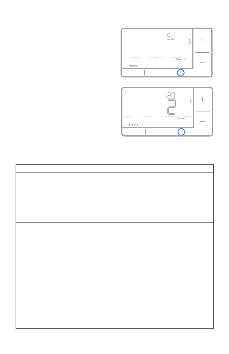
22 Select System Setup options.
Press + or - to change values or
select from available options. Then
press Select to save changes and
advance to the next System Setup
number.
See “System Setup options” below
for a full list of
System Setup
numbers and options
.
Repeat until all of the System
Setup options have been set. The
thermostat will automatically save
and exit to the Home screen.
23 Continue to “System operation
settings” on page 10.
System Setup
Number Description Options (factory default in bold)
120 Scheduling Options
0 = Non-Programmable
1 = 1-Week Programmable
2 = 52 Programmable
4 = 7-Day Programmable
Note: You can change default MOFR, SASU schedule here. To edit
periods during days, temperature setpoints, or to turn Schedule On/Off,
touch MENU and go to SCHEDULE.
125 Temperature Indication Scale
0 = Fahrenheit
1 = Celsius
200 Heating System Type
1 = Conventional Forced Air Heat
2 = Heat Pump
3= Radiant Heat (Boiler)
5 = None (Cool Only)
Note: This option selects the basic system type your thermostat will
control.
205 Heating Equipment Type
Conventional Forced Air Heat:
1 = Standard Efficiency Gas Forced Air
2 = High Efficiency Gas Forced Air
3 = Oil Forced Air
4 = Electric Forced Air
5 = Hot Water Fan Coil
Heat Pump:
7 = Air to Air Heat Pump
Radiant Heat:
9 = Hot Water Radiant Heat
12 = Steam
Note: This option selects the equipment type your thermostat will
control. Note: This feature is NOT displayed if feature 200 is set to Cool
Only.
System Setup options

9
RTH7500 Series
Number Description Options (factory default in bold)
218 Reversing Valve O/B
0 = O (O/B in Cool)
1 = B (O/B in Heat)
Note: This option is only displayed if the Heat Pump configured. Select
whether reversing valve O/B should energize in cool or in heat.
220
Cool Stages / Compressor
Stages 200=Conv / 200=HP
0, 1, 2
Note: Select how many Cool or Compressor stages of your equipment
the thermostat will control. Maximum of 2 Cool/Compressor Stages. Set
value to 0 if you do not have Cool Stage/Compressor Stage.
221
Heat Stages / Backup Heat
Stages Heat Stages
Heat Stages: 1, 2
Backup Heat Stages: 0, 1
Note: Select how many Heat or Aux/E stages of your equipment the
thermostat will control. Maximum of 2 Heat Stages for conventional
systems. Maximum of 1 Aux/E stage for systems with more than 1
heating equipment type. Set value to 0 if you do not have Heat Stage/
Backup Heat Stage.
300 System Changeover
0 = Manual
1 = Automatic
Note: Thermostat can automatically control both heating and cooling
to maintain the desired indoor temperature. To be able to select
“automatic” system mode on thermostat home screen, turn this feature
ON. Turn OFF if you want to control heating or cooling manually.
425 Smart Response
0 = No
1 = Yes
Note: Smart Response is a comfort setting. Heat or Cooling equipment
will turn on earlier, ensuring the indoor temperature will match the
setpoint at the scheduled time. See page 15.
430
Minimum Cool Temperature
Setpoint
50 °F to 99 °F (50 °F)
10.0 °C to 37.0 °C (10.0 °C)
Note: The cool temperature cannot be set below this level.
431
Maximum Heat Temperature
Setpoint
40 °F to 90 °F (90 °F)
4.5 °C to 32.0 °C (32.0 °C)
Note: The heat temperature cannot be set above this level.
711
Air Filter 1 Replacement
Reminder
0 = Off
1 = 10 Run Time Days
2 = 20 Run Time Days
3 = 30 Run Time Days
4 = 45 Run Time Days
5 = 60 Run Time Days
6 = 90 Run Time Days
7 = 120 Run Time Days
8 = 150 Run Time Days
9 = 30 Calendar Days
10 = 45 Calendar Days
11 = 60 Calendar Days
12 = 75 Calendar Days
13 = 3 Calendar Months
14 = 4 Calendar Months
15 = 5 Calendar Months
16 = 6 Calendar Months
17 = 9 Calendar Months
18 = 12 Calendar Months
19 = 15 Calendar Months
Note: Set a reminder for when to change your air filter. Choose either
calendar or equipment run time-based reminder.
1415 Daylight saving time
0 = Off
1 = On
Note: Set to Off in areas that do not follow Daylight Saving Time.
NOTE: Once you have cycled through all of the System Setup numbers, Done is
displayed. Press Select to save and exit.
10
Quick Installation Guide
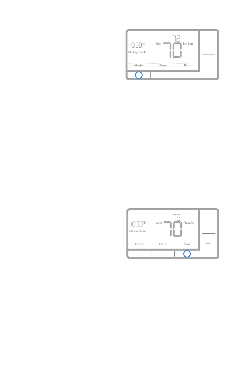
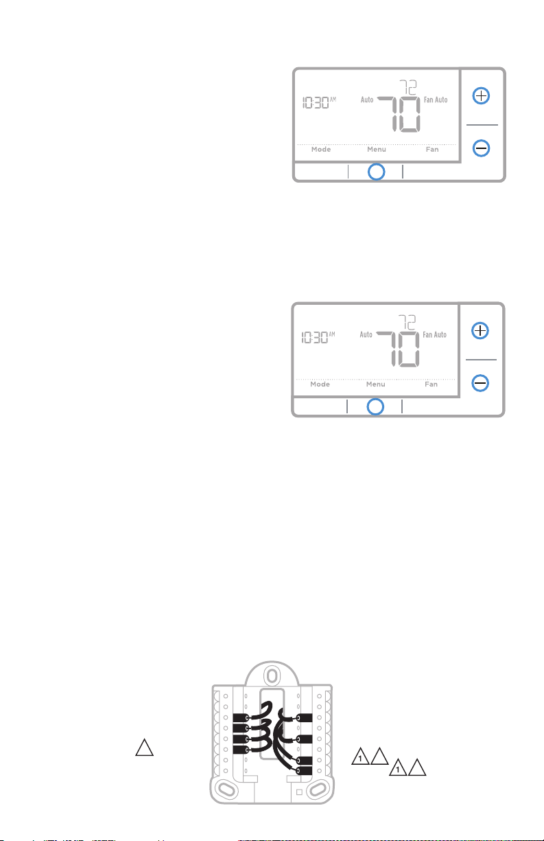
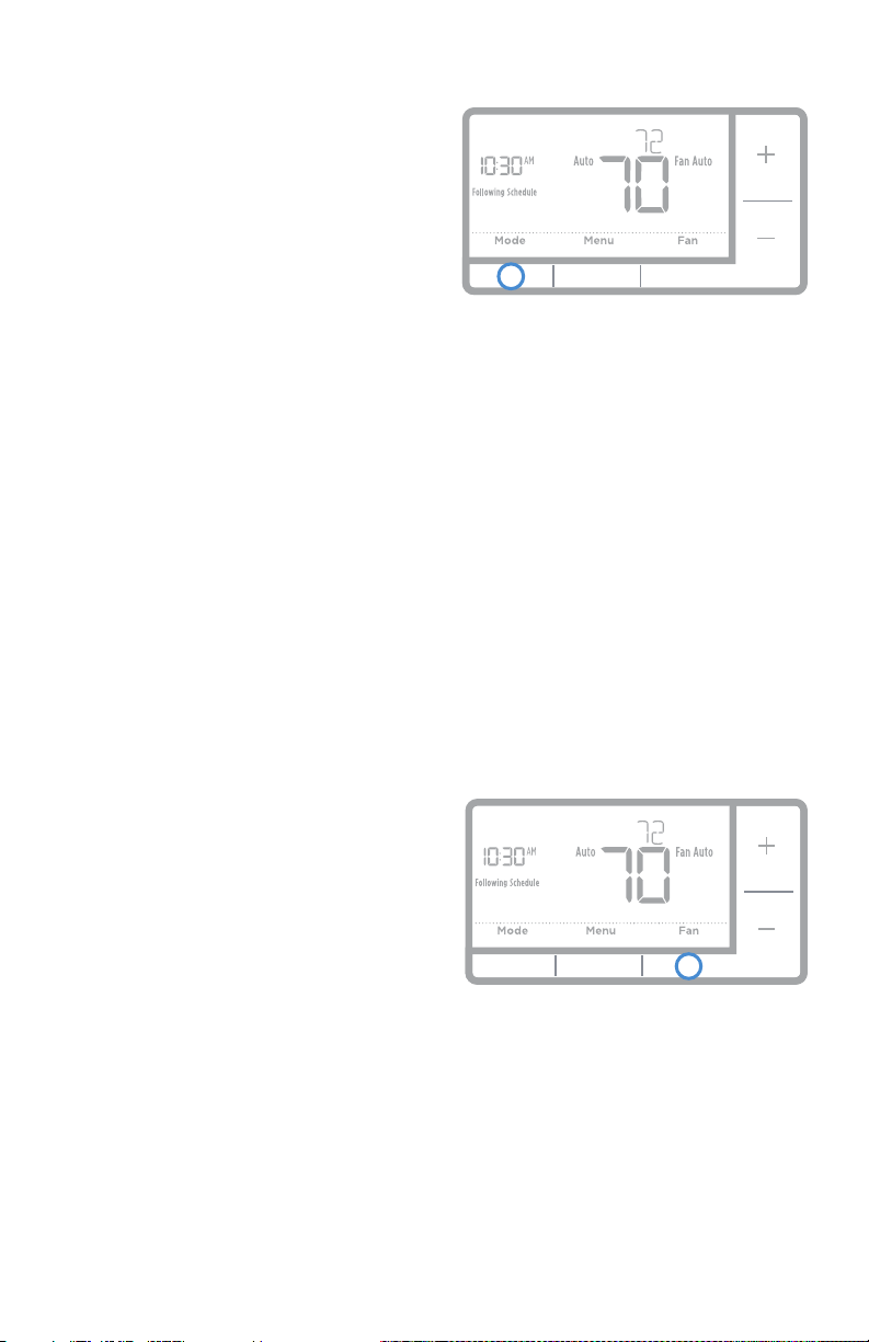
Fan operation settings
1 Press the Fan button to cycle to the
next available Fan mode.
2 Cycle through the modes until the
required Fan mode is displayed and
leave it to activate.
NOTE: Available Fan modes vary with
system settings.
Fan modes:
‒ Auto: Fan runs only when the
heating or cooling system is on.
‒ On: Fan is always on.
‒ Circ: Fan circulates randomly
about 33% of the time.
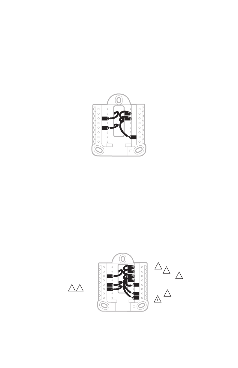
System operation settings
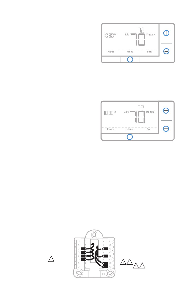
1 Press the Mode button to cycle to the
next available System mode.
2 Cycle through the modes until the
required System mode is displayed
and leave it to activate.
NOTE: Available System modes vary by
model and system settings.
System modes:
‒ Auto: Thermostat selects heating
or cooling as needed.
‒ Heat: Thermostat controls only the
heating system.
‒ Cool: Thermostat controls only the
cooling system.
‒ Em Heat (only for heat pumps
with auxiliary heat): Thermostat
controls Auxiliary Heat. Compressor
is not used.
‒ Off: Heating and cooling system is
off. Fan will still operate if fan is set
to On or Circulate.
NOTE: Heat/Cool flash for 5 minutes
due to compressor protection.
11
RTH7500 Series
Program Schedule
To adjust program schedules
You can program four time periods each day, with different settings for weekdays
and weekends. We recommend the pre-set settings (shown in the table below),
since they can reduce your heating/cooling expenses.
Wake - Set to the time you wake up and the
temperature you want during the morning, until you
leave for the day.
Away - Set to the time you leave home and the
temperature you want while you are away (usually an
energy-saving level).
Home - Set to the time you return home and the
temperature you want during the evening, until
bedtime.
Sleep - Set to the time you go to bed and the
temperature you want overnight (usually an energy-
saving level).
NOTE: To temporarily or permanently override any of the above program
schedules, see page 12.
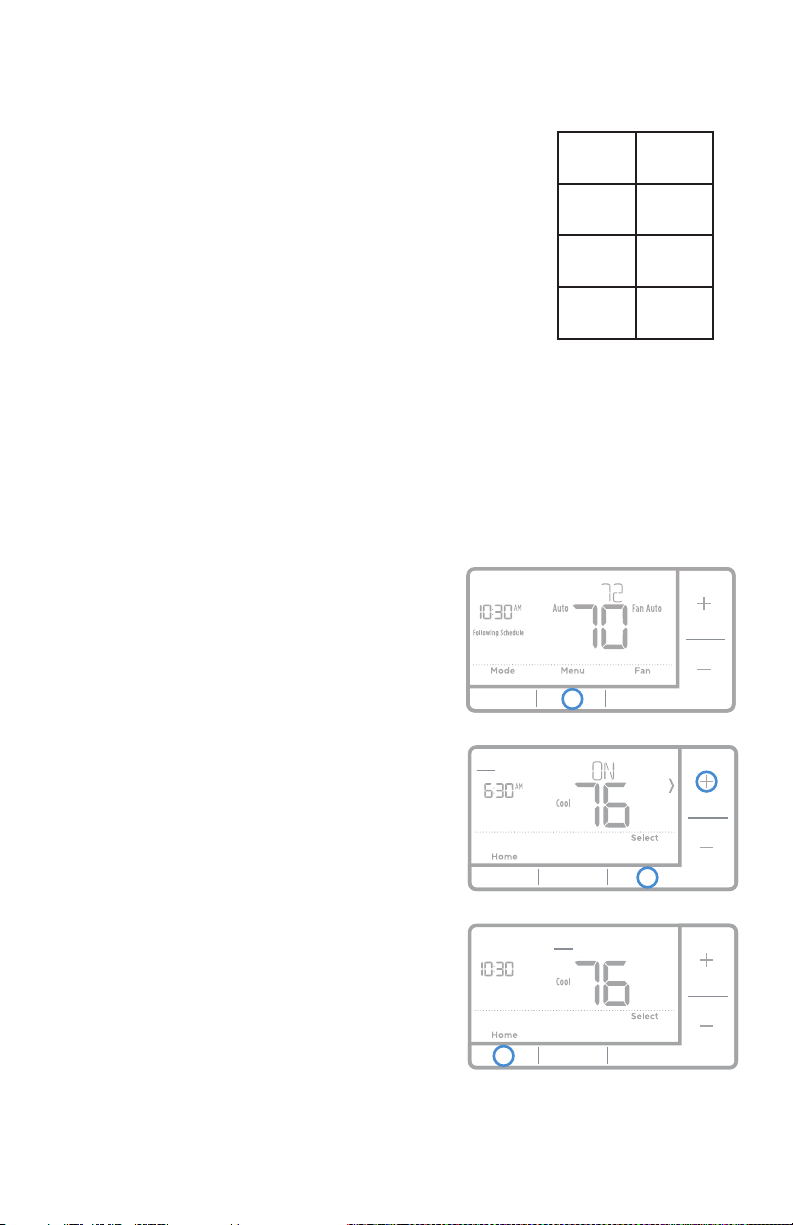
1 Press Menu on your thermostat.
2 PROG is displayed. Press Select. Then
ON is displayed. Press Select.
3 Press + or - to select day or set of
days to edit. Press Select.
4 Press + or - to select a schedule
period to edit (Wake, Away, Home,
and Sleep). Press Select.
5 ON is displayed. Press Select to keep
the schedule period on. Or press
+ and then Select to turn off the
schedule period.
6 Time starts blinking. Press + or - to
adjust the schedule period start
time. Press Select.
7 Temperature starts blinking. Press
+ or - to adjust the “Heat” setpoint
temperature. Press Select. Press +
or - to adjust the “Cool” temperature
setpoint. Press Select.
8 Repeat steps 4 through 7 for the
remaining schedule periods.
9 Press Home when you’re finished to
save program settings and return to
the home screen.
Back
Mon Tue Wed Thu Fri Sat Sun
Wake Away Home Sleep
Back
Mon Tue Wed Thu Fri Sat Sun
Wake Away Home Sleep
PM
Heat Cool
Wake
(6:00 am)
70
°
78
°
Away
(8:00 am)
62
°
85
°
Home
(6:00 pm)
70
°
78
°
Sleep
(10:00
pm)
62
°
82
°
The above table is only an example.
12
Quick Installation Guide
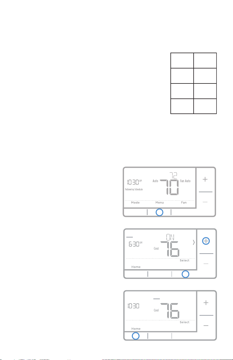
Program schedule override (permanent)
Program schedule override (temporary)
1 Press + or - to adjust the temperature.
2 Once at the desired setpoint
temperature, no further action
is needed. The new setpoint
temperature will be held until the
next scheduled time period begins.
For more information on schedule
time periods, see “Program Schedule”
on page 11.
3 To cancel the Temporary Hold, Press
+ or - and then press Cancel.
1 Press + or - to adjust the temperature.
2 TEMPORARY HOLD is displayed
and the setpoint temperature flashes.
While it’s flashing, press Hold (Mode)
button to change to Permanent Hold.
3 To cancel the Permanent Hold, press
+ or - and then press Cancel.
Wiring—conventional systems
Alternate wiring (conventional systems)
If labels do not match terminals, connect wires as shown below (see notes, below).
NOTES:
1. If you must connect both R and Rc wires, set the R Slider Tab to the down
position (2 wires).
2. If your old thermostat had both R and RH wires, set the R Slider Tab to the
down position (2 wires). Then connect the R wire to the Rc terminal, and the
RH wire to the R terminal.
3. If your old thermostat had only 1 C or C1 wire, connect it to the C terminal. If
your old thermostat had 2 C or C1 wires, wrap each separately with electrical
tape and do not connect them.
AUX
S
S
Y
U
U
G
C
Y
A
Rc
W
K
W
2
R
L/A
O/B
E
Y
3
2
2
2
or Y1 or M
or F
or C1 or X or B
or W1 or H
or R
or RH or 4 or V
Temporary Hold
Permanent Hold
13
RTH7500 Series
Wiring—heat pump
Connect wires: heat pump
1 Match each labeled wire with same letter on new thermostat.
2 Insert the wires into the matching terminal.
NOTE: If you have difficulty inserting wires, you may have to press down the
terminal push button next to the corresponding terminal.
Labels don’t match?
If labels do not match letters on thermostat, see page 13.
AUX
S
S
Y
U
U
G
C
Y
A
Rc
W
K
W
2
R
L/A
O/B
E
Alternate wiring (for heat pumps only)
NOTES:
1. Keep R Slider Tab in the up position (1 wire).
2. If your old thermostat had both V and VR wires, stop now and contact a
qualified contractor for help.
3. If your old thermostat had separate O and B wires, attach the B wire to the C
terminal. If another wire is attached to the C terminal, stop now and contact
a qualified contractor for help.
4. If your old thermostat had Y1, W1 and W2 wires, stop now and contact a
qualified contractor for help.
AUX
S
S
Y
U
U
G
C
Y
A
Rc
W
K
W
2
R
L/A
O/B
E
2
3 5
3
4
5
or X or B
or F
or Y1 or M
2
or H or B
or R
or V or VR
or W or W1 or W2
or X or X2
or F
14
Quick Installation Guide
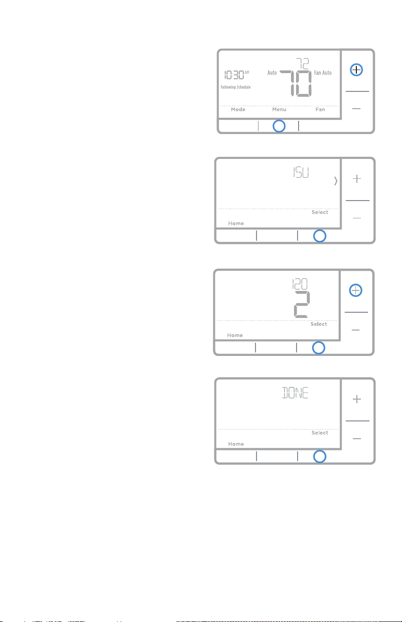
Advanced menu
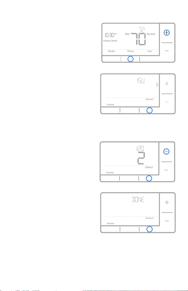
1 Press and hold Menu and +
buttons
for approximately 5 seconds to enter
advanced menu.
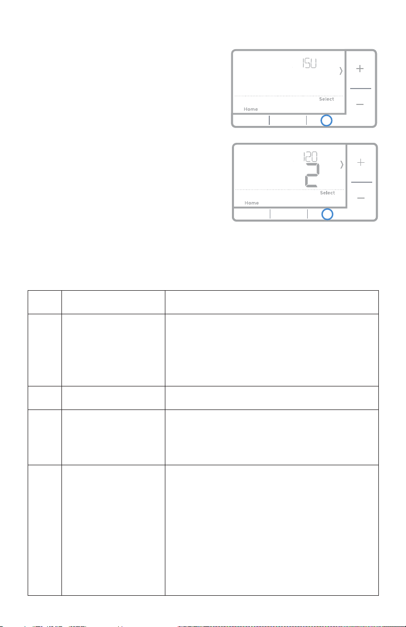
2 Press Select to enter System Setup
(ISU) menu.
3 Press Select to cycle through System
Setup numbers.
NOTE: See “System Setup options”
on page 8 for a full list of
System Setup numbers and options.
4 Press + or - to change values or
select from available options.
5 Press Select to save changes and
advance to the next System Setup
number.
6 Once you have cycled through all of
the System Setup numbers, “Done”
is displayed. Press Select to save and
exit.
To save and exit early, press Home to
return to the Home screen.
Back
15
RTH7500 Series
Smart Response® Technology
This feature allows the thermostat to “learn” how long the furnace and air
conditioner take to reach programmed temperature settings, so the temperature
is reached at the time you set. For example: Set the Wake time to 6 am, and the
temperature to 70°. The heat will come on before 6 am, so the temperature is 70°
by the time you wake at 6. The message “Recovery” is displayed when the system
is activated before a scheduled time period.
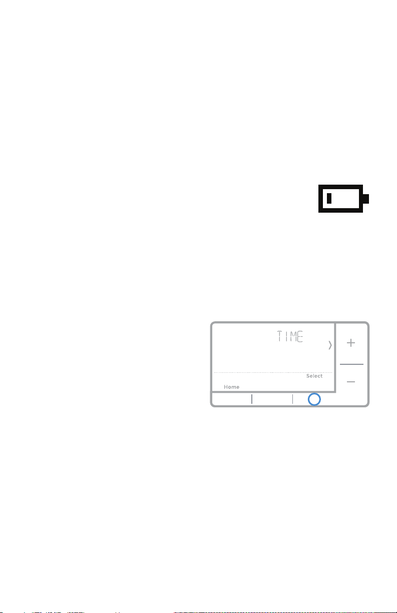
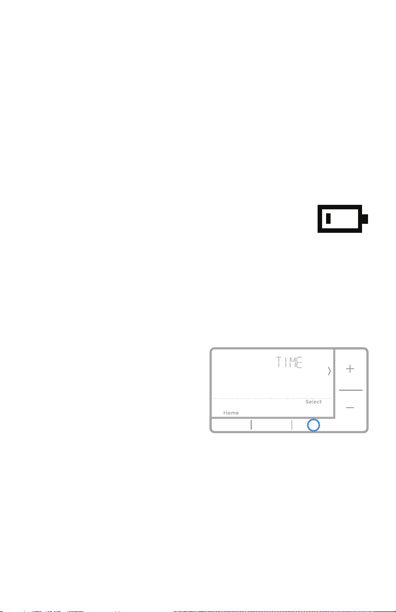
Batteries are required to provide power. Install fresh batteries immediately when
the low battery icon appears. The icon appears about two months before the
batteries are depleted.
Even if the low battery icon does not appear, you should replace
batteries once a year, or before leaving home for more than a
month.
If batteries are inserted within two minutes, the time and day will not have to be
reset. All other settings are permanently stored in memory, and do not require
battery power.
NOTE: When replacing batteries, alkaline batteries are recommended.
1 Press Menu to enter the device menu.
You will see PROG. Press + or - to
choose TIME.
2 Press Select.
3 12HR is displayed. Press + or - to
choose a 12 hour clock or a 24 hour
clock. Press Select.
4 Set the time. Press + or - to adjust
the hour. Press Select.
5 Press + or - to adjust the minutes.
Press Select.
6 Press Select to save and exit.
Setting the time
Battery replacement
16
Quick Installation Guide
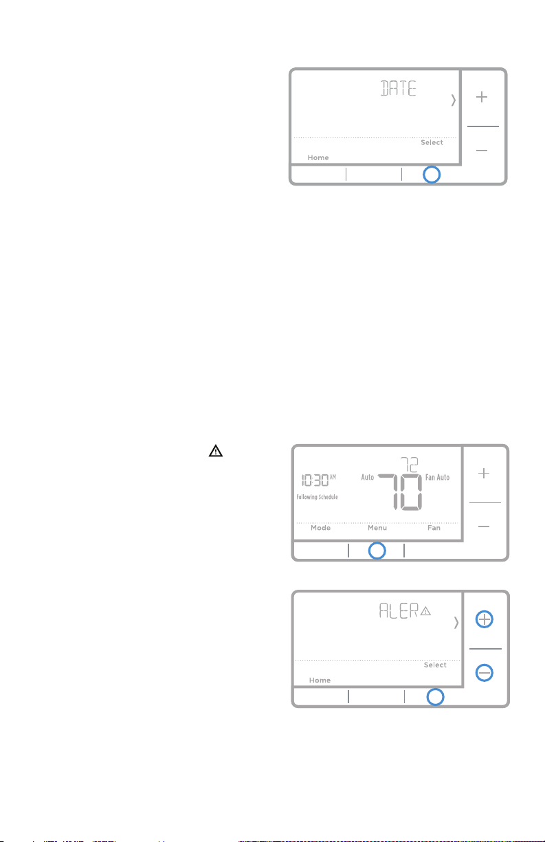
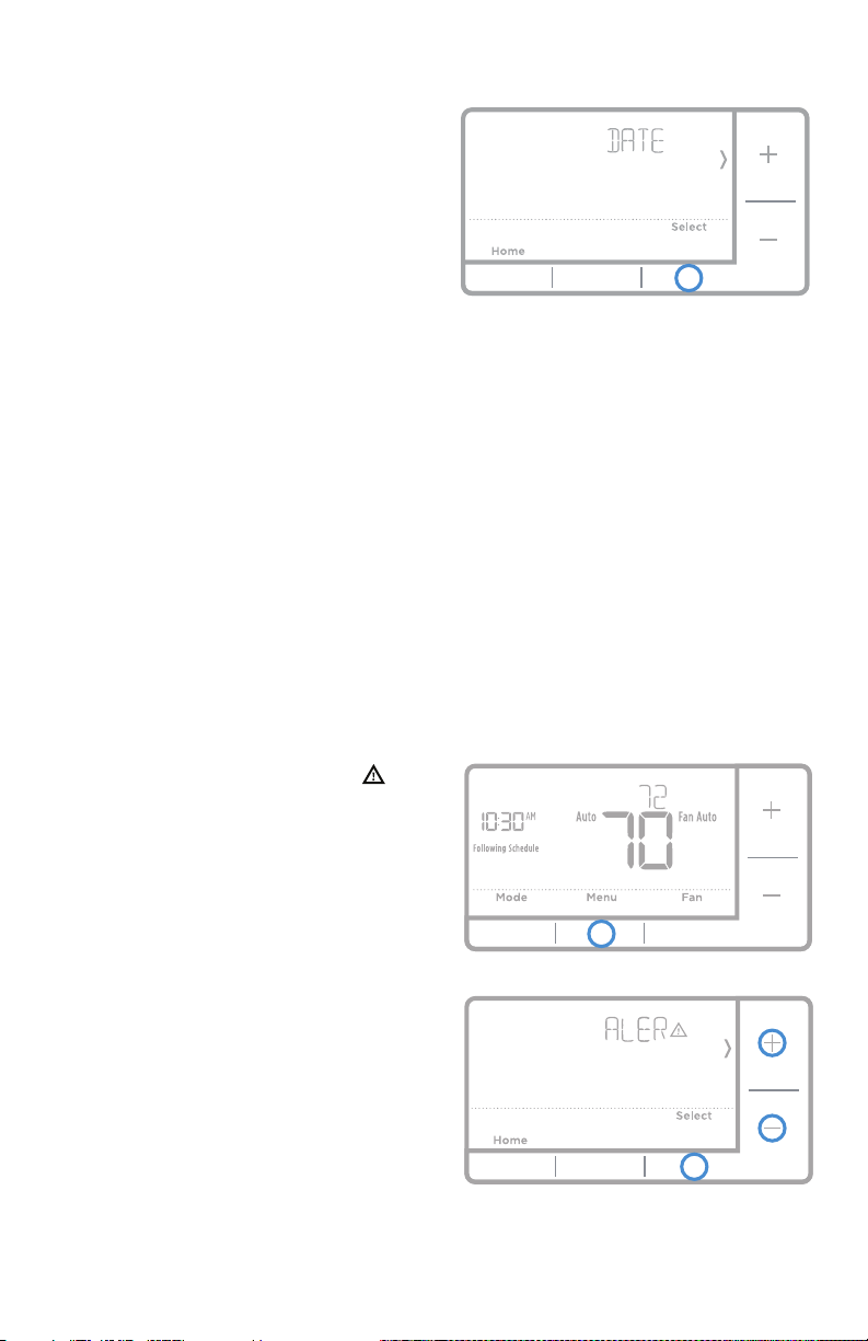
1 Press Menu to enter the device menu.
You will see PROG. Press + or - to
chose DATE.
2 Press Select.
3
You will see the year blinking.
Press +
or - to adjust the year. Press Select.
4 Press + or - to adjust the month.
Press Select.
5 Press + or - to adjust the day. Press
Select to save and exit.
Set the date
1 Press Menu to enter the device menu. You will see PROG. Press + or - to
choose F/C.
2 Press Select.
3 You will see F or C displayed.
4 Press + or - to adjust to the desired setting. F for Fahrenheit and C for Celsius.
Press Select to save and exit.
Setting degrees Fahrenheit (F) or Celsius (C)
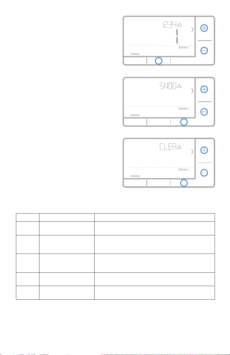
Alert screen
1 You will see the alert icon on the
home screen. You can access alerts
in the Menu to view the error/alert
code. Once viewed the home screen
will maintain the alert symbol until it
is cleared.
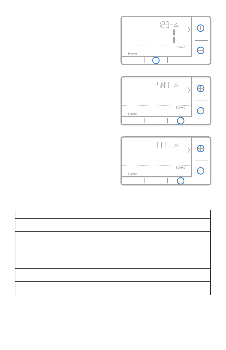
2 Snoozed alerts will appear 7 days
after dismissing them in the alerts
menu screen.
17
RTH7500 Series
3
When the alert icon appears, check
the error code with the table below to
determine the problem.
4 Snooze the alert.
5 Dismiss the alert.
Number Alert/Reminder Definition
170 Internal Memory Error The memory of the thermostat has encountered an
error. Please replace the thermostat.
173 Thermostat
Temperature Sensor
Error
The sensor of the thermostat has encountered an
error. Please replace the thermostat.
181 Replace Air Filter (1) Replace air filter (1). Reset the timer by touching
the "dismiss" button on thermostat screen after it is
replaced.
405 Low Battery Alert The batteries are getting low. Replace them within two
months.
407 Critical Low Battery The batteries are almost depleted and should be
replaced as soon as possible.
Alerts codes

18
Quick Installation Guide
If you have difficulty with your thermostat, please try the following suggestions.
Most problems can be corrected quickly and easily.
Display is blank If you’re using batteries, make sure fresh AA alkaline batteries are
properly installed (see page 6).
Cannot change system
setting to Cool
Check System Setup Option 220 to make sure the options are set
to either 1 or 2 (see page 9).
Fan does not turn on when
heat is required
Check System Setup Option 205 to make sure it is set to match
your heating equipment (see page 8).
Heating system is running
in cool mode
Check System Setup Option 200 or 218 to make sure it is set to
match your heating and cooling equipment (see page 9).
Heating or cooling system
does not respond
Press System to set system to Heat. Make sure the temperature is
set higher than the Inside temperature.
Press System to set system to Cool. Make sure the temperature is
set lower than the Inside temperature.
Check circuit breaker and reset if necessary.
Make sure power switch at heating & cooling system is on.
Make sure furnace door is closed securely.
Wait 5 minutes for the system to respond.
Heat On / Cool On
flashing on the screen
Compressor protection feature is engaged. Wait 5 minutes for the
system to restart safely, without damage to the compressor.
Heat pump issues cool air
in heat mode, or warm air
in cool mode
Check System Setup Option 200 or 218 to make sure it is set to
match your heating and cooling equipment (see page 9).
Troubleshooting

19
RTH7500 Series
Honeywell warrants this product, excluding battery, to be free from defects in
the workmanship or materials, under normal use and service, for a period of
one (1) year from the date of purchase by the consumer. If at any time during
the warranty period the product is determined to be defective or malfunctions,
Honeywell shall repair or replace it (at Honeywell’s option).
If the product is defective,
(i) return it, with a bill of sale or other dated proof of purchase, to the place from
which you purchased it; or
(ii) call Honeywell Customer Care at 18004681502. Customer Care will make
the determination whether the product should be returned to the following
address: Honeywell Return Goods, Dock 4 MN103860, 1985 Douglas Dr. N.,
Golden Valley, MN 55422, or whether a replacement product can be sent to you.
This warranty does not cover removal or reinstallation costs. This warranty shall
not apply if it is shown by Honeywell that the defect or malfunction was caused by
damage which occurred while the product was in the possession of a consumer.
Honeywell’s sole responsibility shall be to repair or replace the product within
the terms stated above. HONEYWELL SHALL NOT BE LIABLE FOR ANY LOSS
OR DAMAGE OF ANY KIND, INCLUDING ANY INCIDENTAL OR CONSEQUENTIAL
DAMAGES RESULTING, DIRECTLY OR INDIRECTLY, FROM ANY BREACH OF ANY
WARRANTY, EXPRESS OR IMPLIED, OR ANY OTHER FAILURE OF THIS PRODUCT.
Some states do not allow the exclusion or limitation of incidental or consequential
damages, so this limitation may not apply to you.
THIS WARRANTY IS THE ONLY EXPRESS WARRANTY HONEYWELL MAKES ON
THIS PRODUCT. THE DURATION OF ANY IMPLIED WARRANTIES, INCLUDING
THE WARRANTIES OF MERCHANTABILITY AND FITNESS FOR A PARTICULAR
PURPOSE, IS HEREBY LIMITED TO THE ONEYEAR DURATION OF THIS
WARRANTY.
Some states do not allow limitations on how long an implied warranty lasts, so
the above limitation may not apply to you. This warranty gives you specific legal
rights, and you may have other rights which vary from state to state.
If you have any questions concerning this warranty, please write Honeywell
Customer Relations, 1985 Douglas Dr, Golden Valley, MN 55422 or call 1800
4681502. In Canada, write Retail Products ON1502H, Honeywell Limited/
Honeywell Limitée, 35 Dynamic Drive, Toronto, Ontario M1V4Z9.
1-year limited warranty
Automation and Control Solutions
Honeywell International Inc.
1985 Douglas Drive North
Golden Valley, MN 55422
customer.honeywell.com
® U.S. Registered Trademark.
© 2016 Honeywell International Inc.
33-00202ES—01 M.S. 09-16
Printed in U.S.A.
33-00202ES-01
For assistance with this product,
please visit
http://yourhome.honeywell.com.
Or call Honeywell Customer Care
toll-free at 18004681502.
Customer assistance
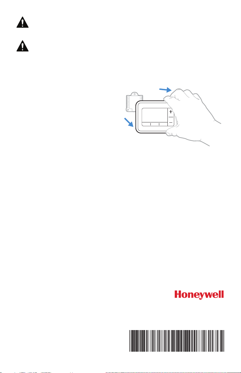
Pull to remove the
thermostat from the
UWP.
CAUTION: MERCURY NOTICE
If this product is replacing a control that contains mercury in a sealed
tube, do not place the old control in the trash. Contact your local waste
management authority for instructions regarding recycling and proper
disposal.
CAUTION: ELECTRICAL HAZARD
Can cause electrical shock or equipment damage. Disconnect power before
beginning installation.

Guía de instalación
rápida
Serie RTH7500
Termostato programable
Herramientas que
necesitará
Herramientas que podría
necesitar
Alicates
Pinzas de punta Taladro y broca
(7/32 pulg.)
Su caja incluye
Tornillos y
anclajes
Sistema de
montaje UWP
(UWP)
Termostato
RTH7500
Guía de instalación
rápida
Destornillador de hoja plana pequeño
Destornillador de estrella
Lápiz
Nivel
2
Guía de instalación rápida
Remoción del termostato antiguo
2 Verifique que el sistema se
encuentre apagado.
Cambie la temperatura en el
termostato antiguo. Si no escucha
que el sistema se enciende en el
plazo de 5 minutos, el suministro
de energía eléctrica se encuentra
desconectado.
Nota: Si tiene un termostato digital
con una pantalla en blanco, omita
este paso.
1 Desconecte el suministro de
energía eléctrica.
Para protegerse usted y el equipo,
desconecte el suministro de
energía eléctrica desde la caja
de interruptores de circuito o el
interruptor que controla el sistema
de calefacción/refrigeración.
3 Quite la placa frontal del
termostato antiguo.
En la mayoría de los termostatos,
puede quitar la placa frontal tirando
de ella con suavidad. Algunos
termostatos pueden tener tornillos,
botones o trabas.
¡No desconecte ningún cable del
termostato en ese momento!
75
4 Asegúrese de que no haya cables
de 120/240 V.
¿Hay cables negros gruesos con
empalmes para cables?
¿Hay cables negros gruesos con
empalmes para cables?
Si respondió de manera afirmativa a
cualquiera de estas preguntas, tiene
un sistema de voltaje de línea y el
termostato no funcionará.
Si no está seguro, visite:
yourhome.honeywell.com/support
Empalme para
cables
Cable negro
grueso
Caja de interruptores
de circuito
Interruptor
Apagado
Encendido
Apagado
3
Serie RTH7500
5 Tome una foto de cómo se ve el
cableado en este momento.
Asegúrese de incluir las letras que se
encuentran al lado de los terminales
donde se insertan los cables. Esta
será una referencia útil al cablear el
termostato.
Consejo: Si los cables se han
decolorado o si 2 terminales
tienen el mismo color de cable,
use las etiquetas para cables que
se suministran en el paquete para
etiquetar cada cable.
6 Quite todos los puentes.
Un puente conecta un terminal con
otro. Puede verse como una grapa
pequeña o un cable de color y debe
quitarse antes de continuar. Use un
destornillador para quitar los cables
de los terminales.
El termostato RTH7500 no
necesita puentes.
Y
R RC
Ejemplo de
un puente
Terminales
7 Registre si hay cables en los siguientes terminales. No cuente los puentes.
El termostato no necesita puentes.
Terminal Cable del color
R
R
H
Rc
8 Escriba el color de los cables.
Marque los cables conectados a los terminales. Al lado del cuadro marcado,
escriba el color del cable. No cuente los puentes.
Marque todos los que correspondan (no todos corresponden):
Terminal Cable del color
Y
Y2
G
C
Terminal Cable del color
A o L/A
O/B
W2 o AUX
E
W
K
El termostato RTH7500 no es compatible con terminales L/A, S o U.
Si hay cables en terminales no listados, será necesario soporte para
cableado adicional. Visite yourhome.honeywell.com/support para
determinar si el termostato funcionará.
4
Guía de instalación rápida
9 Desconecte los cables y quite la placa de pared antigua.
Use un destornillador para quitar los cables de los terminales. A continuación,
use etiquetas para cables a fin de identificar cada cable a medida que lo
desconecta. La letra de la etiqueta para cables debe coincidir con la letra en el
terminal.
Consejo: Para evitar que los cables caigan en el hueco de la pared,
enrósquelos alrededor de un lápiz.
Instalación del termostato RTH7500
10 Agrupe e inserte los cables a través dla
UWP.
Hale para separar la UWP e inserte el grupo
de cables a través de la parte posterior de la
UWP.
Compruebe que al menos 1/4 de pulgada
(6 mm) quede expuesto para la inserción
fácil en los terminales de cables.
Termostato RTH7500 Tornillos
Sistema de
montaje
UWP
Anclajes Pared
5
Serie RTH7500
11 Inserte los anclajes de pared.
Se recomienda que para el montaje
del termostato use los anclajes de
pared incluidos en la caja.
Puede usar la UWP para marcar
el lugar donde desea colocar los
anclajes de pared.
a) Nivele la placa de pared.
b) Marque la ubicación de los
anclajes de pared con un lápiz.
c) Perfore los agujeros.
d) Inserte los anclajes de pared.
e) Asegúrese de que los tarugos
queden a ras con la pared.
Consejo: Use una broca para taladro
de 7/32 pulgada.
Inserte los cables en los agujeros internos de los terminales en la UWP. Las
lengüetas estarán en la posición inferior una vez insertado el cable.
Si tiene 1 cable R (R, Rh o Rc)
Si tiene 2 cables R (R o Rh y Rc)
o
1. Coloque el
interruptor R
en posición
hacia arriba.
1. Coloque el
interruptor R
en la posición
hacia abajo.
2. Inserte el cable R
(R, Rh o Rc) en el
terminal R.
2. Inserte el cable Rc
en el terminal Rc.
3. Inserte el cable R o
Rh en el terminal
R.
12 Establezca la posición del interruptor R e inserte el(los) cable(s) R.
Coloque el interruptor R en posición hacia arriba o hacia abajo en función de
sus notas de cableado del paso 7.
6
Guía de instalación rápida
14 Monte la UWP y cierre la puerta.
Monte la UWP con los tornillos
provistos. Instale los tres tornillos de
manera segura en la pared. Una vez
finalizado el procedimiento, cierre la
puerta.
15 Confirme que el cableado coincida
con el de la foto.
Confirme que el cableado coincida
con los terminales de la foto tomada
en el paso 5.
Use 3 tornillos n.º
8 11/2” provistos
16 Instale las baterías.
Inserte dos baterías alcalinas AA en la parte posterior del termostato, tal como
se muestra.
17 Coloque el termostato.
Alinee el termostato con la UWP y
presiónelo con firmeza para que
calce correctamente.
13 Conecte los cables del paso 8.
Presione hacia abajo las lengüetas
para insertar los cables en
los agujeros de los terminales
correspondientes en el UWP (un
cable por terminal) hasta que quede
firmemente en su lugar.
Tire suavemente los cables paras
verificar que estén seguros.
Consejo: Si necesita aflojar los
cables, presione hacia abajo las
lengüetas terminales que están a los
lados de la UWP.
Este cableado es solo un ejemplo; el
suyo puede variar.

7
Serie RTH7500
18 Encienda la energía eléctrica.
Encienda la energía eléctrica desde
la caja de interruptores de circuito o
el interruptor que controla el sistema
de calefacción/refrigeración.
19 Configure la fecha.
Presione + o - para ajustar el año.
Presione Select (Seleccionar).
Presione + o - para ajustar el mes.
Presione Select (Seleccionar).
Presione + o - para ajustar el día.
Presione Select (Seleccionar).
20 Elija un formato de reloj.
Presione + o - para establecer el
formato de reloj:
12 horas (estándar para
Norteamérica) o 24 horas. Presione
Select (Seleccionar).
21 Configure la hora.
Presione + o - para ajustar la hora.
Presione Select (Seleccionar).
Presione + o - para ajustar
los minutos. Presione Select
(Seleccionar).
Back
Configuración de fecha y hora
Caja de interruptores
de circuito
Interruptor
Encedido
Apagado
Encedido
8
Guía de instalación rápida
22 Seleccione las opciones de configuración
del sistema.
Presione + o - para cambiar los valores o
seleccionar las opciones disponibles. Luego,
presione Select (Seleccionar) para guardar
los cambios y pasar al siguiente número de
configuración del sistema.
Consulte “Opciones de configuración del
sistema” a continuación para obtener una
lista completa de números y opciones de
configuración del sistema.
Repita la operación hasta ajustar todas las
opciones de configuración del sistema. El
termostato guardará de manera automática
y lo llevará a la pantalla de inicio.
23 Continúe con “Ajustes de funcionamiento
del sistema” en la página 10.
Configuración del sistema
Número Descripción
Opciones (las configuraciones predeterminadas de
fábrica están en negrita)
120 Opciones de programación
0 = No programable
1 = Programable para 1 semana
2 = Programable para 5 días2 días
4 = Programable para 7 días
Nota: Aquí puede cambiar el cronograma predeterminado de MOFR, SASU
(LUNVIE, SÁBDOM). Para editar los períodos durante los días, los puntos de
referencia de temperatura o para activar/desactivar el cronograma, toque MENU
(Menú) y diríjase a SCHEDULE (Cronograma).
125 Escala de indicación de temperatura
0 = Fahrenheit
1 = Centígrados
200 Tipo de sistema de calefacción
1 = Calefacción por aire forzado convencional
2 = Bomba de calor
3 = Calefacción radiante (Caldera)
5 = Ninguna [solo refrigeración]
Nota: Esta opción selecciona el tipo de sistema básico que controlará el
termostato.
205 Tipo de equipo de calefacción
Calefacción por aire forzado convencional:
1 = Aire forzado con gas de eficiencia estándar
2 = Aire forzado con gas de alta eficiencia
3 = Aire forzado a aceite
4 = Aire forzado eléctrico
5 = Ventiloconvector de agua caliente
Bomba de calor:
7 = Bomba de calor aire-aire
Calefacción radiante:
9 = Calefacción radiante por agua caliente
12 = Vapor
Nota: Esta opción selecciona el tipo de equipo que controlará su termostato. Nota:
Esta característica NO aparecerá si la característica 200 se configura en Cool
Only (Solo refrigeración).
Opciones de configuración del sistema

9
Serie RTH7500
Número Descripción
Opciones (las configuraciones predeterminadas de
fábrica están en negrita)
218 Válvula de inversión O/B
0 = O (O/B en refrigeración)
1 = B (O/B en calefacción)
Nota: Esta opción solo aparece si se configura la bomba de calor. Seleccione
si la válvula de inversión O/B debe suministrar energía en refrigeración o en
calefacción
220
Etapas de refrigeración / Etapas del
compresor 200 = Conv. / 200 = HP
0, 1, 2
Nota: Seleccione cuántas etapas de refrigeración o del compresor de su equipo
controlará el termostato. Como máximo, 2 etapas de refrigeración/del compresor.
Configure el valor en 0 si no tiene etapa de refrigeración/etapa del compresor.
221
Etapas de calefacción / Etapas de
calefacción de reserva
Etapas de calefacción: 1, 2
Etapas de calefacción de reserva: 0, 1
Nota: Seleccione cuántas etapas de calefacción o Aux/E de su equipo controlará
el termostato. Como máximo, 2 etapas de calefacción para los sistemas
convencionales. Como máximo, 1 etapa Aux/E para los sistemas con más de
1 tipo de equipo de calefacción. Configure el valor en 0 si no tiene etapa de
calefacción / etapa de calefacción de reserva.
300 Cambio de sistema
0 = Manual
1 = Automático
Nota: El termostato puede controlar de manera automática tanto la calefacción
como la refrigeración, con el fin de mantener la temperatura interna deseada.
Para poder seleccionar el modo de sistema “automático” en la pantalla de inicio
del termostato, active esta característica. Desactívela si desea controlar la
calefacción o la refrigeración de forma manual.
425 Respuesta Smart Response
0 = No
1 = Sí
Nota: Smart Response es un ajuste de comodidad. El equipo de calefacción o
refrigeración se encenderá antes para garantizar que la temperatura interna
coincida con el punto de referencia en el horario programado.
Consulte la
página 15.
430
Punto de referencia mínimo de
temperatura de refrigeración
50 °F a 99 °F (50 °F)
10.0 °C a 37.0 °C (10.0 °C)
Nota: La temperatura de refrigeración no puede configurarse por debajo de este
nivel.
431
Punto de referencia máximo de
temperatura de calefacción
40 °F a 90 °F (90 °F)
4.5 °C a 32.0 °C (32.0 °C)
Nota: La temperatura de calefacción no puede configurarse por encima de este
nivel.
711
Recordatorio de reemplazo del filtro
de aire 1
0 = Apagado
1 = 10 días de funcionamiento
2 = 20 días de funcionamiento
3 = 30 días de funcionamiento
4 = 45 días de funcionamiento
5 = 60 días de funcionamiento
6 = 90 días de funcionamiento
7 = 120 días de funcionamiento
8 = 150 días de funcionamiento
9 = 30 días calendario
10 = 45 días calendario
11 = 60 días calendario
12 = 75 días calendario
13 = 3 meses calendario
14 = 4 meses calendario
15 = 5 meses calendario
16 = 6 meses calendario
17 = 9 meses calendario
18 = 12 meses calendario
19 = 15 meses calendario
Nota: Configure un recordatorio de cuándo debe cambiar el filtro de aire. Elija si
el recordatorio se basará en los días calendario o en los días de funcionamiento
del equipo.
1415 Horario de verano
0 = Apagado
1 = Encendido
Nota: Configúrelo como Off (apagado) en las regiones en que no se sigue un
horario de verano.
NOTA: Una vez haya realizado el ciclo a través de todos los números de
establecimiento del sistema, aparecerá Done (Listo). Presione Select (Seleccionar)
para guardar y salir.
10
Guía de instalación rápida
Ajustes de funcionamiento del ventilador
1 Presione el botón Fan (Ventilador)
para continuar con el siguiente
modo de ventilador disponible.
2 Recorra los modos hasta que
aparezca el modo del ventilador
requerido y déjelo para que se active.
NOTA: Los modos del ventilador
disponibles pueden variar según los
ajustes del sistema.
Modos del ventilador:
‒ Auto (Automático): El ventilador funciona solo cuando el sistema de
calefacción o refrigeración está encendido.
‒ On (Encendido): El ventilador está siempre encendido.
‒ Circ: El ventilador circula de forma aleatoria, aproximadamente el 33 % del
tiempo.
Ajustes de funcionamiento del sistema
1 Presione el botón Mode (Modo) para
continuar con el siguiente modo del
sistema disponible.
2 Recorra los modos hasta que
aparezca el modo del sistema
requerido y déjelo para que se active.
NOTA: Los modos del sistema
disponibles pueden variar según el
modelo y los ajustes del sistema.
Modos del sistema:
‒ Auto (Automático): El termostato selecciona el sistema de calefacción o
refrigeración según sea necesario.
‒ Heat (Calefacción): El termostato controla solamente el sistema de
calefacción.
‒ Cool (Refrigeración): El termostato controla solamente el sistema de
refrigeración.
‒ Em Heat (Calefacción Em) (solamente para bombas de calor con
calefacción auxiliar): El termostato controla el calor auxiliar. No se utiliza el
compresor.
‒ Off (Apagado): El sistema de calefacción y refrigeración está apagado. El
ventilador aún funcionará si está configurado en On (Encendido) o Circulate
(Circular).
NOTA: Heat/Cool (Calefacción/refrigeración) destella durante 5 minutos debido a
la protección del compresor.
11
Serie RTH7500
Cronograma del programa
Para ajustar los cronogramas del programa
Puede programar cuatro períodos de tiempo por
día, con diferentes configuraciones para los días de
semana y los fines de semana. Recomendamos las
configuraciones preestablecidas (que se muestran en
el cuadro que se encuentra a continuación), debido a
que reducen los gastos de calefacción y refrigeración.
Wake (Despertar): Programe la hora en que se
despierta y la temperatura que desea durante la
mañana, hasta que se marche de su casa.
Away (Ausente): Programe la hora en que se va de su
casa y la temperatura que desea mientras no está en
su casa (por lo general, un nivel de ahorro de energía).
Home (En casa): Programe la hora en que regresa a
su casa y la temperatura que desea durante la tarde/
noche hasta que se va a dormir.
Sleep (Descanso): Programe la hora en que se va a dormir y la temperatura que desea
durante toda la noche (por lo general, un nivel de ahorro de energía).
NOTA: Para anular de manera temporal o permanente cualquiera de los cronogramas del
programa anteriores, consulte la página 12.
1 Presione Menu (Menú) en el termostato.
2 Aparecerá PROG. Presione Select
(Seleccionar). Luego aparecerá ON
(Encendido). Presione Select (Seleccionar).
3 Presione + o - para seleccionar el día o
el conjunto de días que desea modificar.
Presione Select (Seleccionar).
4 Presione + o - para seleccionar el período de
cronograma que desea modificar (Wake, Away,
Home y Sleep). Presione Select (Seleccionar).
5 Aparecerá ON (Encendido). Presione Select
(Seleccionar) para mantener encendido
el período de cronograma. De lo contrario,
presione + y luego Select para apagar el
período de cronograma.
6 Time (Hora) comenzará a parpadear. Presione
+ o - para ajustar la hora de inicio del período
de cronograma. Presione Select (Seleccionar).
7 Temperature (Temperatura) comenzará a
parpadear. Presione + o - para ajustar la
temperatura de referencia de Calefacción
(Heat). Presione Select (Seleccionar). Presione
+ o - para ajustar la temperatura de referencia
de Refrigeración (Cool). Presione Select
(Seleccionar).
8 Repita los pasos del 4 al 7 para los períodos
de cronograma restantes.
9 Una vez finalizado el proceso, presione Home
(Inicio) para guardar los ajustes del programa
y regresar a la pantalla de inicio.
Back
Mon Tue Wed Thu Fri Sat Sun
Wake Away Home Sleep
Back
Mon Tue Wed Thu Fri Sat Sun
Wake Away Home Sleep
PM
La tabla anterior solo es un ejemplo.
(Calefacción )(Refrigeración
)
(Despertar
)
(6:00 am)
70
°
78
°
(Ausente)
(8:00 am)
62
°
85
°
(En casa)
(6:00 pm)
70
°
78
°
(Descanso
)
(10:00 pm)
62
°
82
°
Wake
Away
Home
Sleep
Heat Cool
12
Guía de instalación rápida
Anulación del cronograma del programa (permanente)
Anulación del cronograma del programa (temporal)
1 Presione + o - para ajustar la temperatura.
2 Una vez obtenida la temperatura de
referencia deseada, no se requieren
otras acciones. La nueva temperatura
de referencia se mantendrá hasta
que comience el siguiente período
programado. Para obtener información
adicional sobre los períodos de horario
programados, consulte “Cronograma del
programa” en la página 11.
3 Para cancelar la pausa temporal, presione
+ o - y luego presione Cancel (Cancelar).
1 Presione + o - para ajustar la temperatura.
2 Aparecerá TEMPORARY HOLD (Pausa
temporal) y la temperatura de referencia
parpadeará. Mientras parpadea, presione
el botón Hold (Modo) (Pausa) para
cambiar a Permanent Hold (Pausa
permanente).
3 Para cancelar la pausa permanente,
presione + o - y luego presione Cancel
(Cancelar).
Cableado: sistemas convencionales
Cableado alternativo (sistemas convencionales)
Si las etiquetas no corresponden con los terminales, conecte los cables como se muestra a
continuación (consulte las notas a continuación).
NOTAS:
1. Si debe conectar tanto el cable R como el cable Rc, configure la lengüeta deslizante R
a la posición hacia abajo (2 cables).
2. Si el termostato antiguo tenía cables R y RH, configure la lengüeta deslizante R a la
posición hacia abajo (2 cables). Luego, conecte el cable R al terminal Rc y el cable
RH al terminal R.
3. Si el termostato antiguo tenía solo 1 cable C o C1, conéctelo al terminal C. Si el
termostato antiguo tenía 2 cables C o C1, envuelva cada uno por separado con cinta
aislante y no los conecte.
Temporary Hold
Permanent Hold
AUX
S
S
Y
U
U
G
C
Y
A
Rc
W
K
W
2
R
L/A
O/B
E
Y
3
2
2
2
o Y1 o M
o F
o C1 o X o B
o W1 o H
o R
o RH o 4 o V

13
Serie RTH7500
Cableado: Bomba de calor
Conexión de los cables: bomba de calor
1 Haga coincidir cada cable etiquetado con la misma letra en el termostato
nuevo.
2 Inserte los cables en el terminal correspondiente.
NOTA: Si tiene problemas para insertar los cables, es posible que deba
presionar el botón pulsador del terminal que se encuentra al lado del terminal
correspondiente.
¿Las etiquetas no coinciden?
Si las etiquetas no coinciden con las letras en el termostato, consulte la
página 13.
AUX
S
S
Y
U
U
G
C
Y
A
Rc
W
K
W
2
R
L/A
O/B
E
Cableado alternativo (para bombas de calor únicamente)
NOTAS:
1. Mantenga la lengüeta deslizante R en la posición hacia arriba (1 cable).
2. Si el termostato antiguo tenía cables V y VR, deténgase y comuníquese con
un contratista cualificado para obtener ayuda.
3. Si el termostato existente tenía cables O y B separados, conecte el cable
B al terminal C. Si hay otro cable conectado al terminal C, deténgase y
comuníquese con un contratista cualificado para obtener ayuda.
4. Si el termostato antiguo tenía cables Y1, W1 y W2, deténgase y
comuníquese con un contratista cualificado para obtener ayuda.
AUX
S
S
Y
U
U
G
C
Y
A
Rc
W
K
W
2
R
L/A
O/B
E
2
3 5
3
4
5
o X o B
o F
o Y1 o M
2
o H o B
o R
o V o VR
o W o W1 o W2
o X o X2
o F
14
Guía de instalación rápida
Menú avanzado
1 Mantenga presionados los botones
Menú y + durante aproximadamente
5 segundos para acceder al menú
avanzado.
2 Presione Select (Seleccionar) para
acceder al menú de Configuración
del sistema (ISU).
3 Presione Select (Seleccionar)
para recorrer los números de
configuración del sistema.
NOTA: Consulte “Opciones de
configuración del sistema” en la
página 8 para obtener una lista
completa de números y opciones de
configuración del sistema.
4 Presione + o - para cambiar los
valores o seleccionar las opciones
disponibles.
5 Presione Select (Seleccionar) para
guardar los cambios y pasar al
siguiente número de configuración
del sistema.
6 Una vez recorridos todos los
números de configuración del
sistema, aparecerá “Done” (Done).
Presione Select (Seleccionar) para
guardar y salir.
Para guardar y salir antes, presione
Home (Inicio) para regresar a la
pantalla de inicio.
Back
15
Serie RTH7500
Tecnología Smart Response®
Esta característica permite que el termostato “sepa” cuánto demora su equipo
de calefacción y su aire acondicionado en alcanzar las configuraciones de
temperatura programadas, de manera que se alcance esa temperatura a la hora
que usted la configuró. Por ejemplo: Configure la hora de despertarse a las 6 a.m.
y la temperatura en 70 °F (21.1 °C). La calefacción se activará antes de las 6 a.m.
para que la temperatura sea de 70 °F (21.1 °C) a las 6 a.m., cuando programó
despertarse. Se mostrará el mensaje “Recovery” (Recuperación) cuando el sistema
esté activado antes de un período de tiempo programado.
Se requiere el uso de baterías para generar energía. Instale las baterías nuevas
inmediatamente cuando el ícono de low battery (baterías bajas) aparezca. El icono
aparece aproximadamente dos meses antes de que se agoten las baterías.
Incluso si el icono de batería con poca carga no aparece, debe
reemplazar las baterías una vez al año o antes de abandonar el
hogar por más de un mes.
Si coloca las baterías en el lapso de dos minutos, no tendrá que volver a configurar
la hora y el día. Todos los otros ajustes están almacenados de manera permanente
en la memoria y no requieren suministro energía de la batería.
NOTA: Se recomienda reemplazar las baterías por baterias alcalinas.
1 Presione el botón Menu para ingresar
al menú del artefacto. Usted verá
PROG. Presione + o - para escoger
TIME (HORA).
2 Presione Select (seleccionar).
3 Luego aparecerá 12HR. Presione
+ o - para escoger el formato de reloj
de 12 horas o de 24 horas. Presione
Select (seleccionar).
4 Configure la hora. Presione + o -
para ajustar la hora.
Presione Select
(seleccionar).
5 Presione + o - para ajustar
los minutos. Presione Select
(seleccionar).
6 Presione Select (Seleccionar) para
guardar y salir.
Configuración de hora
Reemplazo de las baterías
16
Guía de instalación rápida
1 Presione el botón Menu para ingresar
al menú del artefacto. Usted verá
PROG. Presione + o - para escoger
DATE (FECHA).
2 Presione Select (seleccionar).
3
Usted verá titilar el año. Presione
+ o
-
para ajustar el año.
Presione Select
(seleccionar).
4
Presione
+ o - para ajustar el mes.
Presione Select (seleccionar).
5
Presione
+ o - para ajustar el día.
Presione Select (Seleccionar) para
guardar y salir.
Configuración de fecha
1 Presione el botón Menu para ingresar al menú del artefacto. Usted verá PROG.
Presione + o - para escoger F/C.
2 Presione Select (seleccionar).
3 Usted verá F o C en la pantalla.
4 Presione + o - para ajustar la temperatura deseada. F para Fahrenheit y C para
Celsius. Presione Select (Seleccionar) para guardar y salir.
Configuración de los grados Fahrenheit (F) o Centígrados (C)
Pantalla de alerta
1 Usted verá aparecer el icono de
alerta en la pantalla. Usted tendrá
acceso a las alertas en el Menu para
ver el código de error/alerta. Una vez
vista la pantalla principal mantendrá
el símbolo de alerta hasta ser
resuelto.
2 Las alertas de repetición aparecerán
7 días después de ser descartadas
en la pantalla del menú de alertas.
17
Serie RTH7500
3
Cuando aparezca el ícono de
alerta, verifique el código de error
comparándolo con la tabla a
continuación para determinar cuál
es el problema.
Número Alerta/recordatorio Definición
170 Error de la memoria
interna
La memoria del termostato ha encontrado un error.
Por favor reemplace el termostato.
173 Error del sensor de
temperatura del
termostato
El sensor del termostato ha encontrado un error.
Por favor reemplace el termostato.
181 Reemplace el filtro de
aire (1)
Reemplace el filtro de aire (1). Reinicie el temporizador
tocando el botón “Dismiss” (descartar) en la pantalla
del termostato después de reemplazarlo.
405 Alerta de batería baja Las baterías tienen poca carga. Reemplácelas en
menos de dos meses.
407 Batería críticamente
baja
Las baterías están casi agotadas y deben ser
reemplazadas lo más pronto posible.
Códigos de las alertas
4 Repetición de la alerta
5 Descarte de la alerta

18
Guía de instalación rápida
Si tiene dificultades con el termostato, intente seguir las sugerencias que se
indican a continuación. La mayoría de los problemas se pueden solucionar de
manera fácil y rápida.
La pantalla está en blanco Si usa baterías, compruebe que las baterías alcalinas AA nuevas
estén instaladas correctamente (consulte la página 6).
No se puede cambiar la
conguración del sistema
a Cool (Refrigeración)
Revise la opción de conguración del sistema 220 para cercior-
arse de que las opciones estén conguradas en 1 o 2 (consulte la
página 9).
El ventilador no se enci-
ende cuando se requiere
utilizar la calefacción
Revise la opción de conguración del sistema 205 para cerciorarse
de que esté congurado para que corresponda con su equipo de
calefacción (consulte la página 8).
El sistema de calefac-
ción está funcionando en
modalidad de refrigeración
(Cool)
Revise la opción de conguración del sistema 200 o 218 para
cerciorarse de que esté congurado para que corresponda con su
equipo de calefacción y refrigeración (consulte la página 9).
El sistema de calefac-
ción o refrigeración no
responde
Presione System (Sistema) para congurar el sistema en Heat
(Calefacción). Asegúrese de que la temperatura sea más alta que
la temperatura interior.
Presione System (Sistema) para congurar el sistema en Cool (Re-
frigeración). Asegúrese de que la temperatura sea más baja que la
temperatura interior.
Revise el interruptor de circuito y, si es necesario, reinícielo.
Asegúrese de que el interruptor de energía del sistema de
calefacción y refrigeración esté encendido.
Asegúrese de que la puerta del sistema de calefacción esté bien
cerrada.
Espere cinco minutos para que responda el sistema.
Espere cinco minutos para
que responda el sistema.
La función de la protección del compresor está activada. Espere
cinco minutos para que se reinicie el sistema de forma segura, sin
dañar el compresor.
Los problemas con la
bomba de calor hacen que
se enfríe el aire en la mo-
dalidad de calefacción, o
que se caliente el aire en la
modalidad de refrigeración
Revise la opción de conguración del sistema 200 o 218 para
cerciorarse de que esté congurado para que corresponda con su
equipo de calefacción y refrigeración (consulte la página 9).
Localización y solución de problemas

19
Serie RTH7500
Honeywell garantiza, por el período de un (1) año a partir de la fecha de
compra por parte del consumidor, que este producto, sin incluir la batería,
no presentará defectos en los materiales ni de mano de obra, en condiciones
normales de uso y de servicio. Si, en cualquier momento, durante el período
de vigencia de la garantía, se determina que el producto está defectuoso o no
funciona adecuadamente, Honeywell lo reparará o lo reemplazará (a elección de
Honeywell).
Si el producto presenta fallas,
(i) llévelo al lugar donde lo compró, junto con la factura de compra u otra prueba
de compra que incluya la fecha en la que compró el producto, o
(ii) comuníquese con el Servicio de atención al cliente de Honeywell, llamando
al 18004681502. En el Servicio de atención al cliente, determinarán si el
producto debe ser devuelto a la siguiente dirección: Honeywell Return Goods,
Dock 4 MN103860, 1985 Douglas Dr. N., Golden Valley, MN 55422, o si se le
puede enviar un producto de reemplazo.
Esta garantía no cubre los gastos de remoción ni de reinstalación. Esta garantía
no se aplicará si Honeywell demuestra que el defecto o funcionamiento
inadecuado fue causado por daños que se produjeron mientras el producto
estuvo en posesión de un consumidor.
La única responsabilidad de Honeywell será la de reparar o reemplazar el
producto dentro de los términos mencionados anteriormente. HONEYWELL NO
SERÁ RESPONSABLE POR LA PÉRDIDA NI EL DAÑO DE NINGÚN TIPO, QUE
INCLUYE CUALQUIER DAÑO INCIDENTAL O CONSECUENTE QUE RESULTE,
DIRECTA O INDIRECTAMENTE, DE CUALQUIER INCUMPLIMIENTO DE
CUALQUIER GARANTÍA, EXPRESA O IMPLÍCITA, O DE CUALQUIER OTRA FALLA
DE ESTE PRODUCTO. Algunos estados no permiten la exclusión o limitación
de daños incidentales o resultantes, de manera que esta limitación puede no
aplicarse en su caso.
ESTA GARANTÍA ES LA ÚNICA GARANTÍA EXPRESA QUE HONEYWELL REALIZA
SOBRE ESTE PRODUCTO. LA DURACIÓN DE CUALQUIERA DE LAS GARANTÍAS
IMPLÍCITAS, INCLUIDAS LAS GARANTÍAS DE APTITUD E IDONEIDAD PARA UN
FIN DETERMINADO, QUEDA, POR EL PRESENTE, LIMITADA A LA DURACIÓN DE
UN AÑO DE ESTA GARANTÍA.
Esta garantía es la única garantía expresa que honeywell realiza sobre este
producto. La duración de cualquiera de las garantías implícitas, incluidas las
garantías de aptitud e idoneidad para un fin determinado, queda, por el presente,
limitada a la duración de un año de esta garantía.
Si tiene preguntas acerca de esta garantía, escriba a Honeywell Customer
Relations: 1985 Douglas Dr, Golden Valley, MN 55422, o llame al
18004681502. En Canadá, escriba a Retail Products: ON1502H, Honeywell
Limited/Honeywell Limitée, 35 Dynamic Drive, Toronto, Ontario M1V4Z9.
Garantía limitada de 1 año

33-00202ES-01
® Marca Registrada en los E.U.A
© 2016 Honeywell International Inc.
33-00202ES—01 M.S. 09-16
Impreso en los EE. UU.
Soluciones de automatización y control
Honeywell International Inc.
1985 Douglas Drive North
Golden Valley, MN 55422
customer.honeywell.com
Para obtener ayuda sobre este
producto, visite
http://yourhome.honeywell.com.
También puede comunicarse con el
número gratuito del Servicio al cliente
de Honeywell al 18004681502.
Asistencia al cliente
Tire para retirar el
termostato dla UWP.
PRECAUCIÓN: AVISO SOBRE MERCURIO
Si este producto está reemplazando a un control que contiene mercurio en
un tubo sellado, no tire a la basura el control anterior. Contacte a la oficina
de manejo de desechos de su localidad para averiguar la forma de reciclar y
desechar adecuadamente el producto.
PRECAUCIÓN: PELIGRO DE ELECTROCUCIÓN
Puede causar descargas eléctricas o daños al equipo. Desconecte el
suministro eléctrico antes de comenzar la instalación.