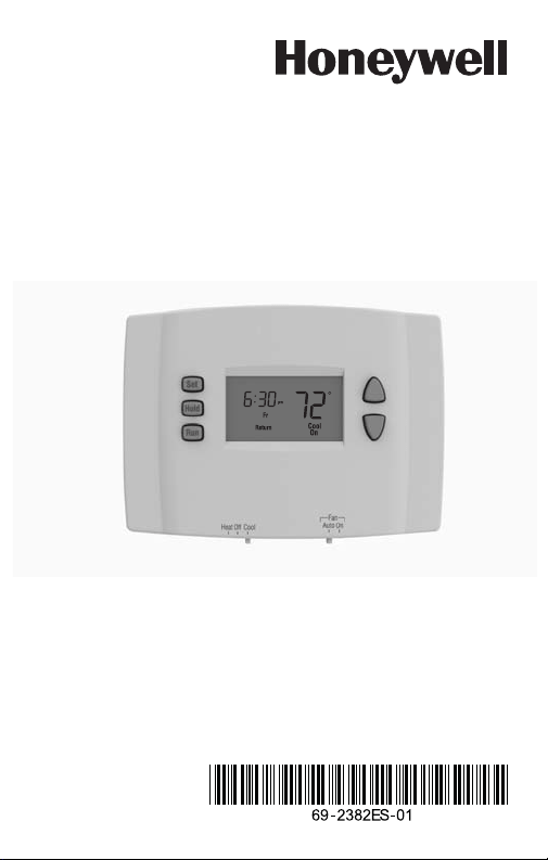
Quick Installation Guide
RTH2410
5-1-1 Programmable Thermostat
69-2382ES-01 (RTH2410 5-1-1 QIG) ENG USA.fm Page -1 Monday, October 19, 2009 3:59 PM

Do you need assistance?
We are here to help.
Call 1-800-468-1502.
69-2382ES-01 (RTH2410 5-1-1 QIG) ENG USA.fm Page 0 Monday, October 19, 2009 3:59 PM

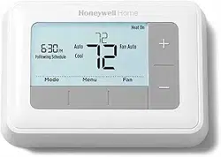
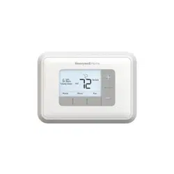
Programmable Thermostat RTH2410
1
This thermostat is compatible with the following
systems:
• Gas, oil or electric furnace
• Central air conditioner
• Hot water system with or without pump
• Millivolt system
• Central heating and cooling system
• Heat pump without auxiliary/backup heat
• Heat pump with auxiliary/backup heat
n
Identify System Type
1.
This thermostat cannot be used on
multistage systems.
69-2382ES-01 (RTH2410 5-1-1 QIG) ENG USA.fm Page 1 Monday, October 19, 2009 3:59 PM

Quick Installation guide
2
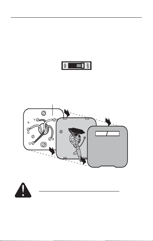
1) Turn power off at the heating/cooling system.
2) Remove old thermostat, but leave wallplate with
wires attached.
MERCURY NOTICE: Do not put your old
thermostat in the trash if it contains mercury in a
sealed tube. Contact your local waste
management authority for instructions regarding
recycling and proper disposal.
o
Remove Old Thermostat
2.
Do not remove wallplate yet.
69-2382ES-01 (RTH2410 5-1-1 QIG) ENG USA.fm Page 2 Monday, October 19, 2009 3:59 PM
Programmable Thermostat RTH2410
3
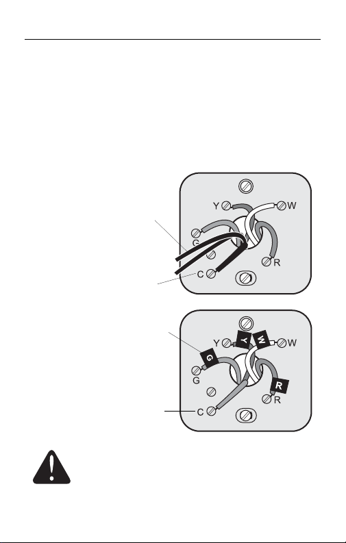
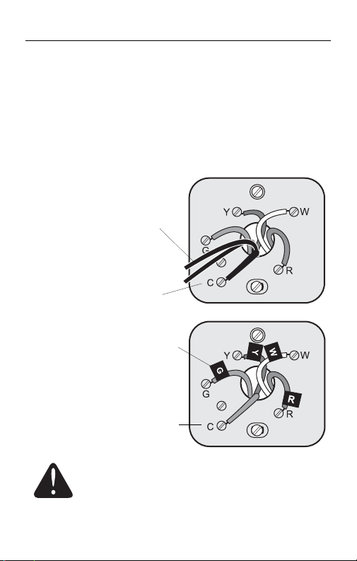
If any wires are not attached to your old thermostat or are
attached to a terminal marked C or C1, they will not be
connected to your new thermostat. Wrap the bare metal end
of each of these wires with electrical tape, so it cannot touch
and short other wires.
Disconnect wires and remove the old wallplate only
after all wires are labeled. Wrap the wires around
a pencil to prevent them from falling though the
wall opening.
p
Identify Wires
3.
Do not use
non-connected wires.
Do not use C or C1 wires
Identify and label each wire.
IGNORE WIRE COLORS:
Use terminal screw
designations to identify
wires.
69-2382ES-01 (RTH2410 5-1-1 QIG) ENG USA.fm Page 3 Monday, October 19, 2009 3:59 PM
Quick Installation guide
4
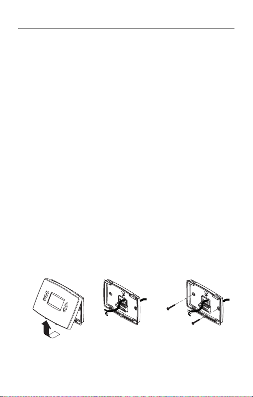
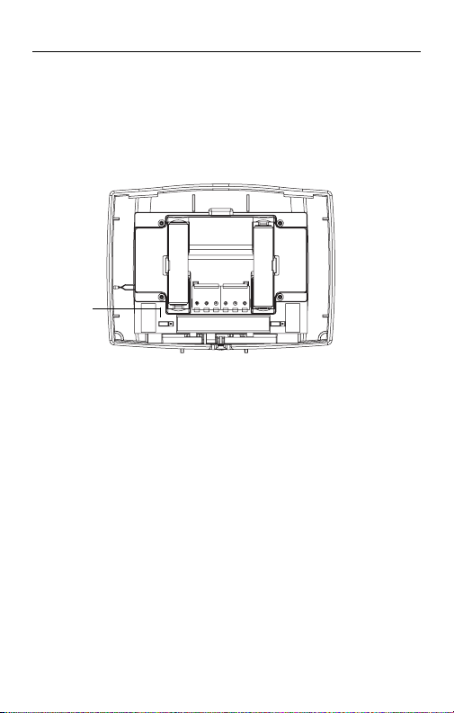
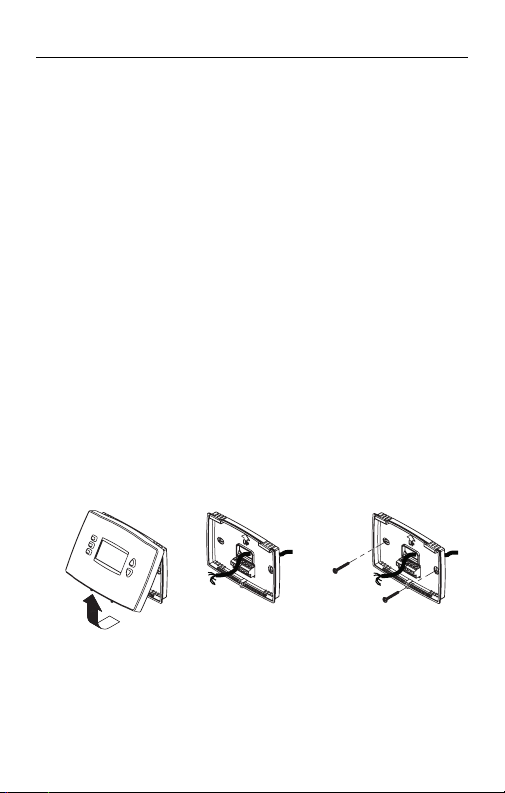
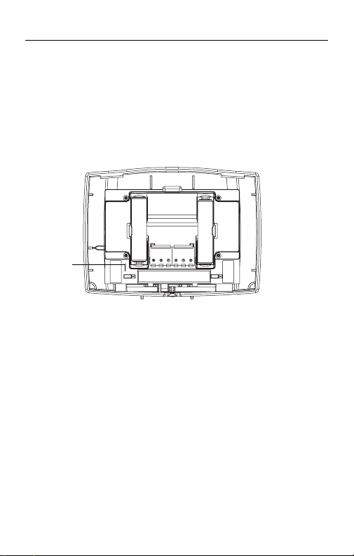
1) Loosen the locking screw at the bottom of the
thermostat. Note that the screw is captive and
cannot be removed from the wallplate.
2) Separate the thermostat from the wallplate as per
Figure 1.
3) Position the wallplate against the wall and mark
hole positions with a pencil.
NOTE: Levelling is for esthetics only and will not
affect the performance of the thermostat.
4) Drill holes at the marked positions and insert
supplied wall anchors.
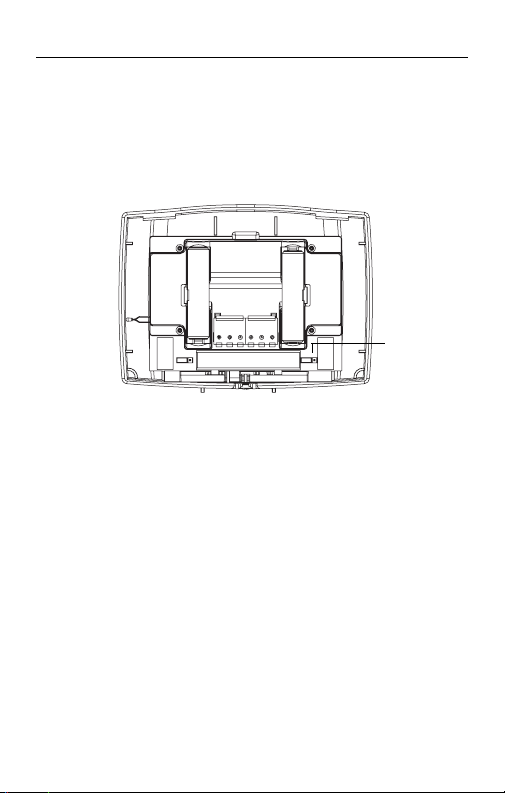
5) Pass the wires through the large opening located
at the bottom center of the wallplate as per
Figure 2.
6) Secure the wallplate to the wall with supplied
mounting screws as per Figure 3.
7) Connect the wires to the terminals.
q
Mount New Wallplate
4.
Figure 1
Figure 2
Figure 3
69-2382ES-01 (RTH2410 5-1-1 QIG) ENG USA.fm Page 4 Monday, October 19, 2009 3:59 PM
Programmable Thermostat RTH2410
5
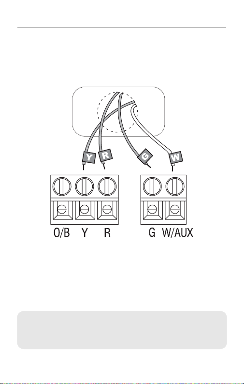
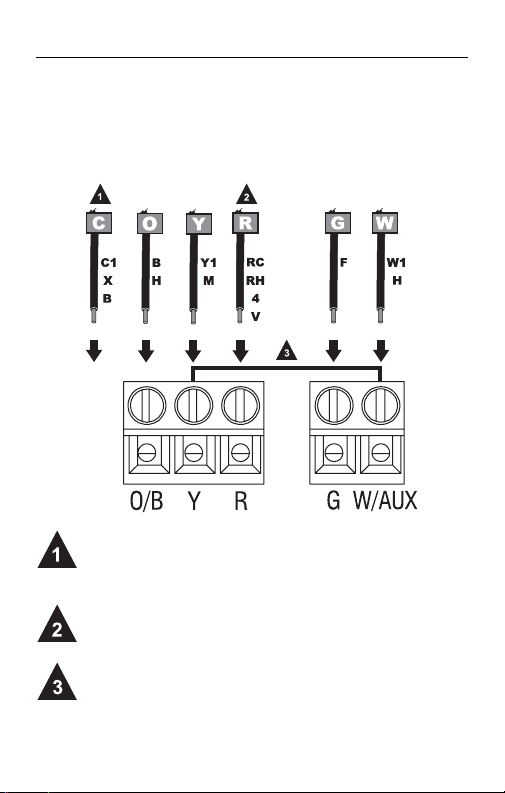
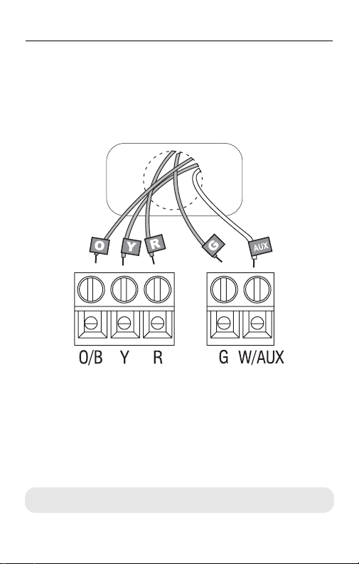
Conventional Systems (Typical Wiring)
1) Match each labeled wire with the terminal having
the same letter.
2) Loosen the terminal screws using a screwdriver,
insert the wires, then tighten the screws.
3) Push any excess wire back into the wall opening.
r
Connect Wires
5.
• Labels don’t match? See page 6.
• Have a heat pump with auxiliary/backup heat, see pages 7-8.
• Call 1-800-468-1502 for wiring assistance.
69-2382ES-01 (RTH2410 5-1-1 QIG) ENG USA.fm Page 5 Monday, October 19, 2009 3:59 PM
Quick Installation guide
6
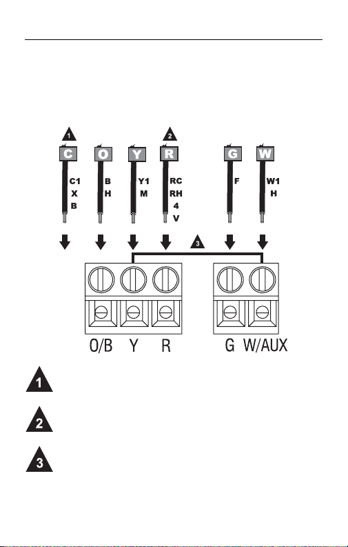
Conventional Systems (Alternate Wiring)
Do not use C, C1 or X wire. Do not use B wire if you already
have O wire. Wrap bare end of wire with electrical tape.
This thermostat cannot be used if your old thermostat had
any two of the following wires: R, RC, RH, 4 and V.
Place a jumper (piece of wire) between Y and W/AUX if you
are using a heat pump without auxiliary/backup heat.
r
Connect Wires (cont’d)
6.
69-2382ES-01 (RTH2410 5-1-1 QIG) ENG USA.fm Page 6 Monday, October 19, 2009 3:59 PM
Programmable Thermostat RTH2410
7
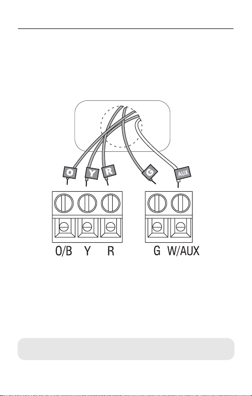
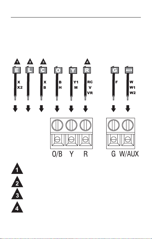
Heat Pump Systems with Auxiliary/Backup Heat
(Typical Wiring)
1) Match each labeled wire with the terminal having
the same letter.
2) Loosen the terminal screws using a screwdriver,
insert the wires, then tighten the screws.
3) Push any excess wire back into the wall opening.
r
Connect Wires (cont’d)
7.
Labels don’t match? See page 8.
69-2382ES-01 (RTH2410 5-1-1 QIG) ENG USA.fm Page 7 Monday, October 19, 2009 3:59 PM
Quick Installation guide
8
Heat Pump Systems with Auxiliary/Backup Heat
(Alternate Wiring)
If your old thermostat had E and Aux wires (or alternate
wires), connect both wires to AUX terminal.
Do not use L wire. Wrap bare end of wire with electrical tape.
Do not use C or X wire. Do not use B wire if you already have
O wire. Wrap bare end of wire with electrical tape.
This thermostat cannot be used if your old thermostat had
any two of the following wires: R, RC, V or VR.
r
Connect Wires (cont’d)
8.
69-2382ES-01 (RTH2410 5-1-1 QIG) ENG USA.fm Page 8 Monday, October 19, 2009 3:59 PM
Programmable Thermostat RTH2410
9
Set jumper JP1, on the back of the thermostat, if you
have connected a wire to the G terminal.
Incorrect jumper setting: An incorrect setting is
noticeable
in a gas or oil heating system. When heating
starts, you will initially feel cold air coming out of the vents
as the fan is running before the furnace has enough time
to heat up the air.
s
Set Heating Fan Control
9.
HG
Leave the jumper in this factory-set
position if you have a gas or oil furnace.
HE
Place the jumper to this position if you
have an electric furnace.
JP1
69-2382ES-01 (RTH2410 5-1-1 QIG) ENG USA.fm Page 9 Monday, October 19, 2009 3:59 PM

Quick Installation guide
10
Set jumper JP2, on the back of the thermostat, if you
have a heat pump.
Incorrect jumper setting: The heat pump operation
will be reversed, i.e., it will cool in Heat mode and will
heat in Cool mode.
t
Set Heat Pump Reversing Valve
10.
O
Leave the jumper in this factory-set
position if you have connected O wire to
the O/B terminal.
B
Place the jumper to this position if you
have connected B wire to the O/B terminal.
JP2
69-2382ES-01 (RTH2410 5-1-1 QIG) ENG USA.fm Page 10 Monday, October 19, 2009 3:59 PM
Programmable Thermostat RTH2410
11
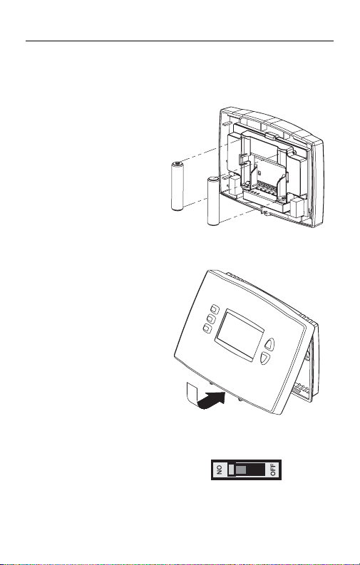
1) Install 2 AAA
batteries on the
back of the
thermostat.
2) Align the two
brackets on the
top of the
thermostat with
the corresponding
slots on the top of
the wallplate.
3) Push the
thermostat
against the
wallplate.
4) Tighten the screw
at the bottom of
the thermostat.
5) Turn power back
on at the heating/
cooling system.
u
Install Batteries and Thermostat
11.
69-2382ES-01 (RTH2410 5-1-1 QIG) ENG USA.fm Page 11 Monday, October 19, 2009 3:59 PM
Quick Installation guide
12
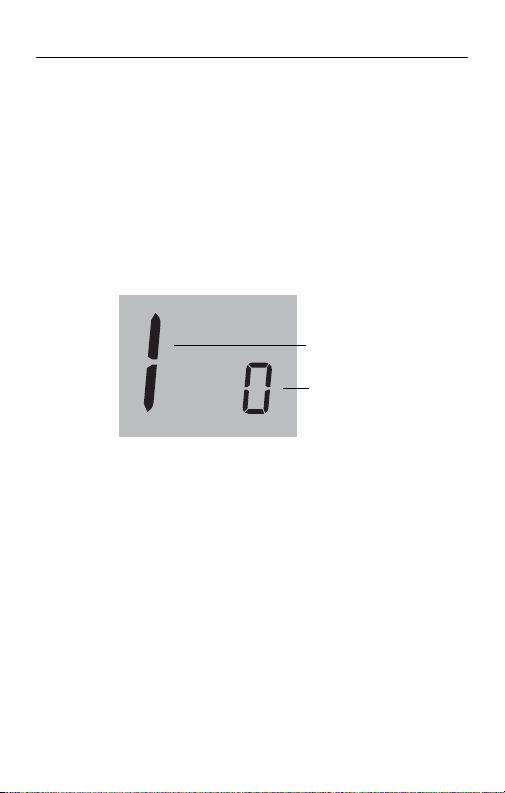
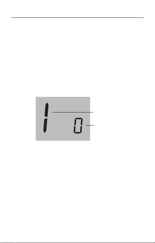
Follow the procedure below to personalize and
configure the thermostat according to the heating/
cooling system.
1) Press the Up and Down buttons simultaneously
(for three seconds) until the display appears as
shown below. See table on the next page.
2) Press the Up or Down button to change the
option.
3) Press the Up and Down buttons simultaneously
for one second to advance to the next function.
4) When the last function is displayed, press the Up
and Down buttons to save any changes and exit
the menu.
NOTE
: If you do not press any button for 60 seconds while you are
in the setup menu, the thermostat automatically saves any changes
made and exits the menu. At any time you can save the changes
and exit by pressing the
Run
button.
v
System Setup
12.
Function
number
Option
number
69-2382ES-01 (RTH2410 5-1-1 QIG) ENG USA.fm Page 12 Monday, October 19, 2009 3:59 PM

Programmable Thermostat RTH2410
13
1
Damage can occur if the compressor is restarted too soon after
shutdown. This feature forces the compressor to wait 5 minutes before
restarting. During the wait time, the message Cool On or Heat On
flashes on the screen. When the safe wait time has elapsed, the
message stops flashing and the compressor turns on.
2
Adaptive Intelligent Recovery
TM
allows the thermostat to “learn” how
long your furnace or air conditioner takes to reach the set
temperature. Simply program the desired times and desired
temperatures into the schedule. The thermostat will determine when
to activate heating or cooling so that the desired temperature is
attained at the desired time.
v
System Setup (cont’d)
13.
Function
Default
setting
Options
1
Temperature
display format
0
0: Fahrenheit
1: Celsius
2 Time display format 0
0: 12-hour display
1: 24-hour display
3
Heating cycles per
hour
5
2 to 6 cycles per hour
• 2: 30 min (steam, gravity)
• 3: 20 min (hot water, 90%+
high-efficiency furnace)
• 4: 15 min (gas or oil)
• 5: 12 min (gas or oil)
• 6: 10 min (electric)
4
Compressor
protection
1
1
0: Off
1: On
5
Adaptive Intelligent
Recovery
2
1
0: Off
1: On
6 System setup 0
0: Conventional system (1H1C)
1: Heat pump system with
auxiliary/backup heat (2H1C)
69-2382ES-01 (RTH2410 5-1-1 QIG) ENG USA.fm Page 13 Monday, October 19, 2009 3:59 PM

Automation and Control Systems
Honeywell International Inc.
1985 Douglas Drive North
Golden Valley, MN 55422
Honeywell Limited
35 Dynamic Drive
Scarborough, Ontario M1V 4Z9
http://DIYthermostats.honeywell.com
Printed in USA
69-2382ES-01 10-09
69-2382ES-01 (RTH2410 5-1-1 QIG) ENG USA.fm Page 14 Monday, October 19, 2009 3:59 PM

Guía de instalación rápida
RTH2410
Termostato programable 5-1-1
69-2382ES-01 (RTH2410 5-1-1 QIG) SPA USA.fm Page -1 Monday, October 19, 2009 4:00 PM

¿Necesita ayuda?
¡Aquí estamos!
LLame al 1-800-468-1502
69-2382ES-01 (RTH2410 5-1-1 QIG) SPA USA.fm Page 0 Monday, October 19, 2009 4:00 PM

Termostato programable RTH2410
1
Este termostato es compatible con los siguientes
sistemas:
• Calefactor a gas, aceite o eléctrico
• Aire acondicionado central
• Sistema de agua caliente con o sin bomba
• Sistema de milivoltios
• Calefacción y aire acondicionado centrales
• Bomba de calor sin calefacción auxiliar
• Bomba de calor con calefacción auxiliar
n
Identificar el tipo de sistema
1.
Este termostato no puede usarse en sistemas
multietapas
69-2382ES-01 (RTH2410 5-1-1 QIG) SPA USA.fm Page 1 Monday, October 19, 2009 4:00 PM
Guía de instalación rápida
2
1) Cortar la electricidad del sistema de calefacción/
aire acondicionado.
2) Retirar el viejo termostato pero dejar la placa
mural con los cables conectados.
ADVERTENCIA SOBRE EL MERCURIO
No arrojar el viejo termostato a la basura si contiene
mercurio en un tubo sellado. Comunicarse con la
autoridad local de gestión de desechos para reciclarlo
o eliminarlo adecuadamente
.
o
Retirar el viejo termostato
2.
No retirar la placa mural todavía
69-2382ES-01 (RTH2410 5-1-1 QIG) SPA USA.fm Page 2 Monday, October 19, 2009 4:00 PM
Termostato programable RTH2410
3
Si en el viejo termostato hubiera cables no conectados o
conectados a un terminal marcado C o C1, estos cables no
se usarán con el nuevo termostato. Recubrir el extremo de
metal desnudo de cada uno con cinta aisladora para que no
puedan tocarse y producir un corto circuito.
Desconectar los cables y retirar la vieja placa mural
sólo después de haber etiquetado los cables.
Enroscar los cables en torno a un lápiz para
impedirles caer dentro del agujero de la pared
.
p
Identificar los cables
3.
No usar cables
no conectados
No usar cables C o C1
Identificar y etiquetar
cada cable
IGNORAR LOS COLORES
DE LOS CABLES:
usar las designaciones de
los tornillos terminales para
identificar los cables
69-2382ES-01 (RTH2410 5-1-1 QIG) SPA USA.fm Page 3 Monday, October 19, 2009 4:00 PM
Guía de instalación rápida
4
1) Aflojar los tornillos de la base del termostato. El tornillo
está cautivo y no se lo puede retirar de la base.
2) Separar el termostato de la placa mural como se indica
en la Figura 1.
3) Colocar la placa mural contra la pared y marcar la
posición de los agujeros con un lápiz.
NOTA: la nivelación se hace por razones estéticas
solamente y no afectará el rendimiento del termostato.
4) Perforar los agujeros en las posiciones marcadas e
introducir los tacos de anclaje provistos para los
tornillos.
5) Pasar los cables por la gran abertura ubicada en la
parte inferior, en el centro de la placa mural, como se ve
en la Figura 2.
6) Fijar la placa mural a la pared con los tornillos provistos,
como en la Figura 3.
7) Conectar los cables a los terminales.
q
Instalar la nueva placa mural
4.
Figura 1
Figura 2
Figura 3
69-2382ES-01 (RTH2410 5-1-1 QIG) SPA USA.fm Page 4 Monday, October 19, 2009 4:00 PM

Termostato programable RTH2410
5
Sistemas convencionales (conexión típica)
1) Hacer coincidir cada cable etiquetado con el
terminal de la misma letra.
2)
Aflojar los tornillos del terminal con un destornillador,
introducir los cables y reajustar los tornillos.
3) Empujar el exceso de cables en el agujero de la
pared.
r
Conectar los cables
5.
• ¿Las etiquetas no coinciden? Ver la pág. 6.
• ¿Bomba de calor con calefacción auxiliar? Ver las págs. 7- 8.
• Llamar al 1-800-468-1502 para asistencia con el cableado.
69-2382ES-01 (RTH2410 5-1-1 QIG) SPA USA.fm Page 5 Monday, October 19, 2009 4:00 PM
Guía de instalación rápida
6
Sistemas convencionales (conexión alternativa)
No usar los cables C, C1 o X. No usar el cable B si ya existe
un cable O. Envolver el extremo desnudo de los cables con
cinta aisladora.
No puede usarse este termostato si el viejo termostato
tuviera dos de los siguientes cables: R, RC, RH, 4 y V.
Poner un puente (trozo de cable) entre Y y W/AUX si se usa
una bomba de calor sin calefacción auxiliar.
r
Conectar los cables (cont.)
6.
69-2382ES-01 (RTH2410 5-1-1 QIG) SPA USA.fm Page 6 Monday, October 19, 2009 4:00 PM
Termostato programable RTH2410
7
Sistemas de bombas de calor con calefactor
auxiliar (conexión típica)
1) Hacer coincidir cada cable etiquetado con el
terminal de la misma letra.
2)
Aflojar los tornillos del terminal con un destornillador,
introducir los cables y reajustar los tornillos.
3) Empujar el exceso de cables en el agujero de la
pared.
r
Conectar los cables (cont.)
7.
¿Las etiquetas no coinciden? Ver la página 8.
69-2382ES-01 (RTH2410 5-1-1 QIG) SPA USA.fm Page 7 Monday, October 19, 2009 4:00 PM

Guía de instalación rápida
8
Sistemas de bombas de calor con calefactor
auxiliar (conexión alternativa)
Si el viejo termostato tiene cables E y Aux (o cables
alternativos), conectar ambos cables al terminal AUX.
No usar el cable L. Envolver el extremo desnudo con cinta
aisladora.
No usar los cables C o X. No usar el cable B si ya hay un
cable O. Envolver el extremo desnudo con cinta aisladora.
No puede usarse este termostato si el viejo termostato
tuviera dos de los siguientes cables: R, RC, V o VR.
r
Conectar los cables (cont.)
8.
69-2382ES-01 (RTH2410 5-1-1 QIG) SPA USA.fm Page 8 Monday, October 19, 2009 4:00 PM
Termostato programable RTH2410
9
Ajustar el puente JP1, en la parte de atrás del termos-
tato, si se conectó un cable al terminal G.
Ajuste incorrecto del puente: un ajuste incorrecto es
evidente en un sistema a gas o a aceite. Cuando la
calefacción se encienda saldrá aire frío de las rejillas,
puesto que el ventilador se puso en marcha antes de
que la estufa pudiera calentar el aire
.
s
Ajuste del control del ventilador
de la calefacción
9.
HG
Dejar el puente en este ajuste de fábrica en
el caso de una estufa a gas o a aceite.
HE
Poner el puente en esta posición en el caso
de una estufa eléctrica.
JP1
69-2382ES-01 (RTH2410 5-1-1 QIG) SPA USA.fm Page 9 Monday, October 19, 2009 4:00 PM
Guía de instalación rápida
10
Ajustar el puente JP2, en la parte de atrás del termos-
tato, en el caso de una bomba de calor.
Ajuste incorrecto del puente: el funcionamiento de
la bomba de calor estará invertido: por ejemplo,
enfriará en modo Calefacción y calentará en modo
Enfriamiento.
t
Ajuste de la válvula de inversión
10.
O
Dejar el puente en este ajuste de fábrica si
hay un cable O conectado al terminal O/B.
B
Poner el puente en esta posición si hay un
cable B conectado al terminal O/B.
JP2
69-2382ES-01 (RTH2410 5-1-1 QIG) SPA USA.fm Page 10 Monday, October 19, 2009 4:00 PM

Termostato programable RTH2410
11
1) Instalar 2 pilas AAA
en la parte de atrás
del termostato.
2) Alinear las dos
lengüetas de la
parte superior del
termostato con las
ranuras
correspondientes
de la parte superior
de la placa mural.
3) Empujar el
termostato contra
la placa mural.
4) Ajustar el tornillo
en la parte inferior
del termostato.
5) Volver a conectar
el sistema de
calefacción/aire
acondicionado
.
u
Instalación de las pilas y del
termostato
11.
69-2382ES-01 (RTH2410 5-1-1 QIG) SPA USA.fm Page 11 Monday, October 19, 2009 4:00 PM
Guía de instalación rápida
12
El procedimiento a continuación permite personalizar
y configurar el termostato según el sistema de
calefacción/enfriamiento.
1)
Presionar los botones Arriba y Abajo al mismo
tiempo (3 seg.) hasta que se vea lo que se indica
en la ilustración. Ver el cuadro en la página
siguiente
.
2) Presionar Arriba o Abajo para cambiar de opción.
3) Presionar Arriba y Abajo al mismo tiempo por un
segundo para ir a la función siguiente.
4) Cuando haya aparecido en pantalla la última
función, presionar Arriba y Abajo para
salvaguardar los cambios y salir del menú.
NOTA
: si no se presiona ningún botón durante 60 segundos
mientras esté abierto el menú de configuración, el termostato
salvaguarda los cambios automáticamente y sale del menú. En
cualquier momento se pueden salvaguardar los cambios y salir del
menú presionando el botón
Run
.
v
Configuración del sistema
12.
Número de
la función
Número de
la opción
69-2382ES-01 (RTH2410 5-1-1 QIG) SPA USA.fm Page 12 Monday, October 19, 2009 4:00 PM

Termostato programable RTH2410
13
1
El compresor puede dañarse si se pusiera en marcha enseguida después
de haberse detenido. Esta función lo obliga a esperar 5 minutos antes de
ponerse en marcha nuevamente, mientras los mensajes Cool On o
Heat On parpadean en la pantalla. Cuando el lapso de seguridad finalice,
el mensaje dejará de parpadear y el compresor se activará.
2
La función Adaptive Intelligent Recovery
TM
permite que el termostato
“aprenda” cuánto le lleva a la estufa o al aire acondicionado para cumplir
con la hora y la temperatura del horario. El termostato determina cuándo
activar la calefacción o el enfriamiento para que la temperatura deseada se
alcance a la hora deseada.
v
Configuración del sistema (cont.)
13.
Función
Ajuste
por
defecto
Opciones
1
Formato de la
temperatura
0
0: Fahrenheit
1: Celsius
2 Formato de la hora 0
0: 12 horas
1: 24 horas
3
Ciclos de
calefacción por hora
5
2 a 6 ciclos por hora
• 2: 30 min. (vapor, gravedad)
• 3: 20 min. (agua caliente, 90%+
estufa de alto rendimiento)
• 4: 15 min. (gas o aceite)
• 5: 12 min. (gas o aceite)
• 6: 10 min. (eléctrica)
4
Protección del
compresor
1
1
0: Desconectada
1: Conectada
5
Adaptive Intelligent
Recovery
2
1
0: Desconectada
1: Conectada
6
Configuración del
sistema
0
0: Sistema convencional (1H1C)
1: Bomba de calor con
calefacción auxiliar (2H1C)
69-2382ES-01 (RTH2410 5-1-1 QIG) SPA USA.fm Page 13 Monday, October 19, 2009 4:00 PM

Sistemas para automatización y control
Honeywell International Inc.
1985 Douglas Drive North
Golden Valley, MN 55422
Honeywell Limited
35 Dynamic Drive
Scarborough, Ontario M1V 4Z9
http://DIYthermostats.honeywell.com
Impreso en EE.UU.
69-2382ES-01 10-09
69-2382ES-01 (RTH2410 5-1-1 QIG) SPA USA.fm Page 14 Monday, October 19, 2009 4:00 PM