Loading ...
Loading ...
Loading ...
Operating Instructions
46
Safety Instructions
Installation Instructions
Troubleshooting TipsConsumer Support
Installation of the range.
Converting to LP Gas (or converting back to natural gas from LP)
This range leaves the factory set for use with natural gas.
If you want to convert to LP gas, the conversion must be
performed by a qualified LP gas installer.
The conversion instructions and LP orifices can be
found attached to the range next to the pressure
regulator.
Keep these instructions and the orifices in case you
want to convert back to natural gas.
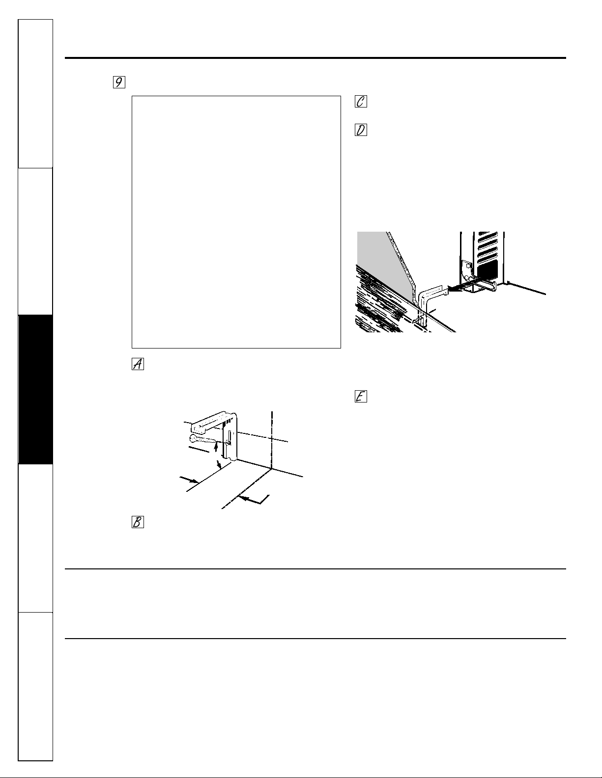
Installing the Anti-Tip Device
Mark the wall where the RIGHT EDGE of the
range is to be located. Be sure to allow for the
countertop overhang if you intend to install
the range next to cabinets.
Locate the outside edge of the device 2
1
⁄
8
″
toward the center of the range from the
marked edge of the range.
Using the device as a template, mark the
position of the hole for the screw.
For wood construction, drill a pilot hole at an
angle of 20 degrees from the horizontal. A nail
or awl may be used if a drill is not available.
Mount the Anti-Tip device with the screw provided.
For cement or concrete construction, you
will need a 1/4″ x 1
1
⁄
2
″ lag bolt and a 1/2″ O.D.
sleeve anchor, which are not provided. Drill
the recommended size hole for the hardware.
Install the sleeve anchor into the drilled hole and
then install the lag bolt through the device. The
bolts must be properly tightened as recommended
for the hardware.
Slide the range against the wall, and check for
proper installation by grasping the front edge
of the cooktop and carefully attempting to tilt
the range forward.
WARNING:
■ Range must be secured with an approved
Anti-Tip device.
■ Unless properly installed, the range could be
tipped by you or a child standing, sitting or
leaning on an open door.
■ After installing the Anti-Tip device, verify that
it is in place by carefully attempting to tilt the
range forward.
■ This range has been designed to meet all
recognized industry tip standards for all
normal conditions.
■ The use of this device does not preclude
tipping of the range when not properly
installed.
■ If the Anti-Tip device supplied with the range
does not fit this application, use the universal
Anti-Tip device WB02X7909.
When All Hookups Are Completed:
MAKE SURE ALL CONTROLS ARE LEFT IN THE OFF
POSITION.
MAKE SURE THE FLOW OF COMBUSTION AND
VENTILATION AIR TO THE RANGE IS UNOBSTRUCTED.
Back of rangeWallboard
Wood screw
Anti-Tip
device
Slotted head screw
Wallplate
Approx.
20°
2
1
⁄
8
”
Marked edge of range
Anti-Tip
device
Loading ...
Loading ...
Loading ...