Loading ...
Loading ...
Loading ...
Installation
60
• verify that the hose is not past its expiry
date (serigraphed on the hose itself).
Make the connection to the gas mains
using a rubber hose whose specifications
comply with current standards (verify that
the reference standard is stamped on the
hose).
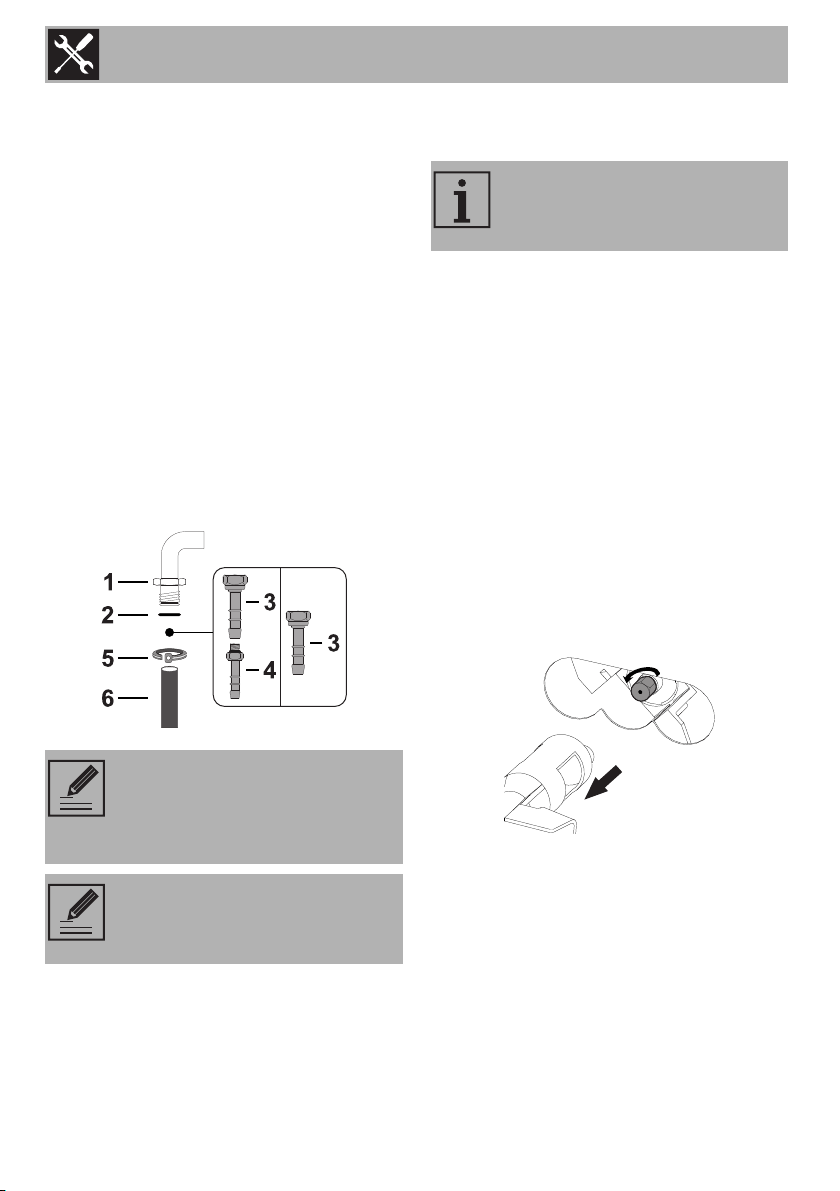
Carefully screw the hose connector 3 to the
appliance’s gas connector 1 (½” thread
ISO 228-1), placing the seal 2 between
them. The hose connector 4 can also be
screwed to the hose connector 3,
depending on the diameter of the gas hose
used. After having tightened the hose
connector(s), push the gas hose 6 onto the
hose connector and secure it with the clamp
that is compliant with the standard in force.
5.3 Adaptation to different types of
gas
In the case of operation with other types of
gas, the burner nozzles must be changed
and the minimum flame adjusted on the gas
taps.
Replacing nozzles
1. Remove the grills and griddle, diffusers
and then the components (see
“Diffusers”).
2. Remove the burners (see “Removing the
burners”).
3. Replace the nozzles using a 7 mm socket
wrench according to the gas to use (see
“Burner and nozzle characteristics
tables”).
4. Reposition the burners in their correct
seats.
Adjusting the minimum setting for natural
gas
Light the burner and turn it to the minimum
position. Extract the gas tap knob and turn
the adjustment screw next to the tap rod
(depending on the model) until the correct
minimum flame is achieved.
Connection using a rubber hose
complying with current standards is
only permitted if the hose can be
inspected along its entire length.
The inside diameter of the hose
must be 8 mm for LPG and 13 mm
for NATURAL GAS.
The appliance is pre-set for liquid
gas at a pressure of 28-30/37
mbar.
Loading ...
Loading ...
Loading ...